Note: Descriptions are shown in the official language in which they were submitted.
CA 02578517 2007-02-14
EXTERNALLY ACCESSIBLE AND ADJUSTABLE OPTIC AND ADJUSTABLE
BASE FOR GROUND-MOUNTED LIGHTING FIXTURE ENCLOSURES
Related Application
The present application claims the benefit of provisional patent application
Serial
No. 60/773,248 filed on February 14, 2006 entitled "Externally Accessible and
Adjustable
Optic and Adjustable Base for Ground-Mounted Lighting Fixture Enclosures," the
entirety of
which is incorporated herein by this reference.
Field of the Invention
This invention relates to features for outdoor ground-mounted lighting fixture
enclosures, and, more particularly, to externally accessible and adjustable
optics and bases
for such lighting fixture enclosures.
Background of the Invention
Free standing lighting fixtures are mounted to the ground to emit light to
illuminate
walkways and other areas. Typically, such fixtures emit light in many
directions but focus
light in one or a few specific directions. Such lights may intentionally use
asymmetric optic
reflectors to selectively illuminate in certain directions more than others
and, thus, will not
emit light uniformly in all directions. For example, a free standing lighting
fixture positioned
next to a walkway may direct light primarily toward the walkway but also
provide some light
that illuminates surrounding bushes, signs, and other objects.
Unfortunately, existing ground-mounted lighting fixture enclosures have
numerous
shortcomings. For example, once installed they do not allow for easy
adjustment of the light
direction because they do not permit adjustment of the optic located inside
the top end of the
enclosure to be carried out from the outside of the enclosure. In contrast, to
adjust the optic,
1
CA 02578517 2007-02-14
the entire top must be removed and inverted. The optic is adjusted or rotated
manually, and
then the entire assembly is replaced. This is time-consuming and inefficient.
Existing free standing lighting fixtures are also mounted to the ground in
ways that
limit adjustment of the orientation of the fixture. The orientation of the
fixture itself (in
addition to the direction of the emitted light) often is important, especially
where the shape of
the fixture has a direction. For example, a series of fixtures each having an
oval-cross
section may be designed to aesthetically coordinate and complement one another
when
directionally aligned and positioned at discrete positions along a walkway,
e.g., aligning the
long axes of the oval cross section of each fixture perpendicular to the
walkway. Existing
enclosures are ill suited for such alignment because they do not allow for
adequate rotational
adjustment. In a typical base, such as the base 27 shown in Fig. 5, the
fixture 25 is installed
by first installing the base 27 using anchor bolts (not shown) and then
positioning a base
support 26, which is mounted to the fixture 25, in one of a limited number of
rotational
orientations (four, in this case) governed by the orientation in which base 24
was anchored to
the ground. Thus, the base 24 must be installed in a precise orientation to
ensure proper
fixture direction. Minor errors in base orientation may destroy an intended
aesthetic. Such
errors can only be corrected, if at all, by the time consuming process of
removing and re-
anchoring the base.
Accordingly, there is a need for ground-mounted lighting fixture enclosures
where the
lighting fixture optic inside the enclosure may be accessed externally and its
positioning
adjusted as desired. Similarly, there is a need for ground-mounted lighting
fixture enclosures
that may be rotated on their respective bases for the purpose of aesthetically
and optically
aligning lighting fixtures to one another and to the surrounding architecture
as desired.
2
CA 02578517 2007-02-14
Summary of the Invention
The present invention provides devices and methods for externally accessing a
lighting fixture optic to adjust its rotational direction. For example,
certain embodiments
provide a lighting fixture enclosure with an opening at the top that both
receives a removable
fastening device (e.g., a screw) for securing the top and, when the fastening
device is
removed, allows insertion of a tool to rotate a reflector and thereby adjust
the direction in
which the light projects from the fixture. Such a reflector may be movably
coupled to an
inside surface of the fixture top. A tool inserted through the opening at the
fixture top may
engage a bracket secured to the reflector such that, as the tool is rotated,
the bracket and
reflector also rotate.
The present invention also provides devices and methods for rotating a
lighting
fixture enclosure on its base. Certain embodiments involve a ground-mounted
base
configured such that a lighting fixture may be attached to the ground-mounted
base and
rotated over a range of rotational orientations. For example, the base may
have a circular
screw contacting frame or other portion that allows set screws of a base
support to secure the
base over a range of rotational orientations.
Brief Description of the Drawings
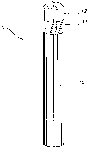
Fig. 1 is a perspective view of a ground-mounted lighting fixture enclosure
according
to an embodiment of this invention, within which the optic of Figs. 2A, 2B,
and 3 and/or the
base of Fig. 5 may be used.
Figs. 2A and 2B show an exemplary embodiment of an externally accessible and
adjustable optic for use in a lighting fixture enclosure according to the
present invention.
3
CA 02578517 2007-02-14
Fig. 3 shows the configuration of Figs. 2A and 2B, with the screw and gasket
removed and a tool inserted to rotate the reflector of the lighting fixture.
Figs. 4A, 4B, and 4C show an exemplary embodiment of a lighting fixture top
and
reflector according to the present invention.
Fig. 5 shows a prior art base for use in a lighting fixture enclosure.
Figs. 6A and 6B are perspective views of an embodiment of a base about which a
lighting fixture enclosure is adjustable according to certain embodiments of
the present
invention.
Detailed Description of the Invention
The present invention provides devices and methods for externally accessing a
lighting fixture optic of a ground-mounted lighting fixture enclosure to
adjust the optic such
that the direction of the light may be altered without complete disassembly of
the top end of
the lighting fixture enclosure or the use of specialized equipment. This
eliminates the
complexity associated with the adjustment of asymmetrical reflectors that are
typically used
in ground-mounted lighting fixture enclosures. In certain embodiments, the
enclosure top is
not removed, but rather the lighting fixture optic is accessed by removing a
fastening device
(e.g., a standard top screw) in the top end of the enclosure and placing a
keyed tool through
the hole. In this manner, fme adjustment can be made easily and checked in
real time.
Because the lighting fixture remains functional during the adjustment (i.e.,
the lamp is on),
an installer may visually inspect the light distribution from the fixture from
ground level after
or during adjustment of the optic. This ability to check results in real time
combined with
being able to access the optic externally without disassembling the enclosure
provides for a
quick and accurate installation of the lighting fixture enclosure.
4
CA 02578517 2007-02-14
Certain exemplary embodiments of this invention may be used in any number of
ground-mounted lighting fixture enclosures. For example, Fig. 1 shows a
suitable lighting
fixture enclosure 5 that includes a fixture top 12 mounted on a fixture body
10, and a light
emitting portion 11 included as a part of the fixture top 12, the fixture body
10, or as a
separate component mounted between the two. Such a device may include an
externally-
accessible optic such as those shown in the exemplary embodiments of Figs. 2A,
2B, and 3.
A fixture top 12 covers the top end of the lighting fixture enclosure 5, which
houses a
light source 13, shown in Fig. 2A. A reflector 14 is housed inside the top end
of the lighting
fixture enclosure and is positioned to reflect light from the light source 13
onto the
surrounding ground below via the light emitting portion 11. Fixture top 12 has
a hole in its
top end through which a removable fastening device can pass. For purposes of
illustration
and discussion, the removable fastening device is shown as a screw 16 with
complimentary
gasket. However, one of skill in the art will understand that any fastening
device capable of
temporary fixation is contemplated by this invention. The fixture top 12 also
includes an
interface 20 (see Fig. 2B) for suspending a reflector 14 while allowing the
reflector 14 to
rotate. A reflector 14 is positioned adjacent the interface 20. A bracket 18
is affixed to the
reflector 14, as shown in Fig. 2A.
To assemble the fixture 5, the screw 16 is inserted through the hole in the
fixture top
12, a hole in the bracket 18, and into a threaded hole in a body connector 15,
which is
mounted to fixture body 10 (not shown). As the screw 16 is tightened, the
fixture top 12 is
drawn closer to the body connector 15 (and thus the fixture body 10). A gasket
may be
provided in the hole in fixture top 12 to seal the hole and ensure that the
screw 16 remains
seated therein.
5
CA 02578517 2007-02-14
In certain embodiments, the reflector 14 is movably coupled to an inside
surface of
the fixture top 12, as shown in Figs. 4A, 4B, 4C. The fixture top 12 includes
three posts 19
(partially shown), each of which has a washer 21 at its end. When the
reflector 14 is
installed in the fixture top 12, the three posts 19 extend in a generally
downward direction to
contact or nearly contact the lip 23 of the reflector 14 in different areas
around the internal
circumference of the lip 23. The washers 21, which are preferably internal
tooth lock
washers, are screwed onto the end of each of the posts 19 where each washer
engages a
different portion along the bottom of the lip 23 of the reflector 14. With the
washers 21 so
engaging the lip 23, the reflector 14 is suspended inside the fixture top 12.
The interactions between the posts 19, washers 21, and lip 23 of the reflector
14 allow
the reflector 14 to be suspended within the fixture top 12 with limited
ability to shift or
wobble, while being free to rotate about its axis. As the reflector 14 is
rotated with respect to
this axes and thus with respect to the posts 19 of fixture top 12, the
reflector's lip 23 is free to
rotate while supported in its suspended position with respect to the fixture
top 12 by the
washers 21. This is because the friction created by the contact between the
washers 21 and
the lip 23 is not sufficient to prevent rotation. In addition, the spatial
relationship between
the posts 19 and/or washers 21 and the lip 23 of the reflector also limits the
amount the
reflector is able to shift or wobble from side to side. One of skill in the
art will understand
that other mechanical retention devices may be used to suspend the reflector
14 within the
fixture top 12.
External access to the reflectors rotational orientation is facilitated in
certain
embodiments through the use of a bracket. The bracket 18, shown in Figs. 2A,
2B, and 3, is
secured to reflector 14 such that the opening in the bracket 18 is coaxial
with the reflector's
6
CA 02578517 2007-02-14
central axis. The opening or aperture in the bracket 18 is configured to allow
passage of the
screw 16 without engaging it while allowing, when the screw 16 is removed, a
tool 24 to
engage and rotate the bracket 18. For example, the opening in the bracket 18
may have a
hexagonal cross-sectional shape to interact with a tool 24 having a hexagonal
cross section
(e.g., an Allen wrench). Such an opening may allow passage and free rotation
of a screw 16
having a generally round but smaller cross section, without the insertion,
removal, or rotation
of the screw 16 impacting the bracket 18 (and thus the reflector 14)
rotational orientation.
When the rotational orientation of reflector 14 requires adjustment, screw 16
is
removed from fixture top 12, but fixture top 12 is left in place at the top
end of the lighting
fixture enclosure 5. A tool, such as the tool 24 shown in Fig. 3, is inserted
through the hole
in fixture top 12 vacated by screw 16 and into engagement with bracket 18. As
explained
above, the hole in bracket 18 is shaped to correspond to the cross-sectional
shape of tool 24.
Reflector 14 is then rotated along axis of rotation 22, shown in Fig. 3, by
moving tool 24 as
desired. Once reflector 14 is in the desired position, tool 24 is removed and
screw 16 is
inserted to again secure fixture top 12 at the top end of the lighting fixture
enclosure 5.
The invention also provides devices and methods for externally rotating a
ground-
mounted lighting fixture enclosure such that lighting fixture enclosures may
be aesthetically
and optically aligned with one another and to the surrounding architecture.
This allows the
rotation of the lighting fixture to be adjusted. Certain embodiments, although
not all, allow
the fixture to be rotated a full 360 degrees in any direction before fmal
tightening. A base
providing the ability for the lighting fixture enclosure to be adjusted or
rotated eliminates the
need to precisely measure, square, and set in concrete (or other substrate)
the anchor bolts,
which is otherwise necessary in existing systems where the lighting fixture
enclosures are
7
CA 02578517 2007-02-14
intended to be aligned with respect to each other and surrounding
architecture. Certain
embodiments also provide the ability for precise real time adjustment of the
lighting fixture
enclosure with respect to other enclosures and the surrounding architecture.
In certain
embodiments, the base can accommodate any anchor bolt orientation and may be
used with
lighting fixture enclosures of any of a number of shapes.
Certain exemplary embodiments of this invention may be used in any number of
ground-mounted lighting fixture enclosures. For example, a suitable lighting
fixture
enclosure is shown in Fig. 1. Fig. 6A shows an exemplary embodiment of an
adjustable base
system according to the present invention. The base 34 generally includes
frame 42 and at
least one flange 44 that extends outwardly from the frame. In the illustrated
embodiment, the
frame is circular-shaped and includes mounting apertures 40. The frame need
not be circular
shaped but rather may be any shape. Moreover, while three mounting apertures
40 are
shown, any number may be used. The illustrated flange 44 is substantially
circular-shaped,
which, as explained below, enables the lighting fixture enclosure 5 to be
rotated through 360
degrees relative to the base 34. Other embodiments may use any suitable shape
that allows
partial (e.g., less than 360 degrees) or complete (e.g., 360 degrees)
rotational freedom.
A base support 32 is provided on the inside of the bottom end 36 of lighting
fixture
enclosure 5. Base support 32 may be affixed to enclosure 5 using any
mechanical retention
means, all of which are well understood by those skilled in the art, or may be
integrally
formed with the enclosure 5. Base support 32 is shaped to receive base 34 and
in particular
flange 44 of the base 34.
To install enclosure 5 in the ground, the base 34 is mounted to the desired
ground
surface by inserting anchor bolts or other securing devices (not shown) into
mounting
8
CA 02578517 2007-02-14
apertures in the base 34. Then, bottom end 36 of the enclosure 5 is placed
over base 34 so
that flange 44 of base 34 is seated in base support 32. Set screws 38 are then
tightened,
clamping base 34 to base support 32 of enclosure 5.
Tightening one or more of the set screws 38 prevents any further rotation of
enclosure
36 about base 34. For example, the set screws 38 may each be made of a
relatively hard
material such as steel and have a cone point that, when tightened, bears
against, digs into
and/or deforms the frame 42 of base 34, which may be made of a softer material
such as cast
aluminum. If rotational adjustment is later desired, the set screws 38 may
simply be
loosened, enclosure 5 adjusted by rotating the entire enclosure (including the
base support 32
about the base 34 (which is fixed relative to the ground), and the set screws
38 tightened
once again.
That the frame 42 of the base 34 with which the set screws 38 interact is
circular
ensures that the provided set screws 38 will always be able to interact with
the frame 42 of
the base 34 and thereby fix the orientation of the enclosure 5, regardless of
that orientation.
Other embodiments can utilize bases of other shapes and characteristics that
permit partial or
complete rotation of the enclosure 5 around a base. For example, portions of
the base 34
may form arcs that allow a limited range of rotation. Moreover, while in the
illustrated
embodiment four set screws 38 are used to clamp base 34 to base support 32,
any number of
set screws may be used or other mechanisms for securely engaging base 34 to
base support
32 or to enclosure 5 may be used, as is well understood by those skilled in
the art. However,
it is preferable, but certainly not required, that at least one pair of
opposing set screws 38 be
used.
9
CA 02578517 2007-02-14
The components used to implement devices according to the inventions described
herein may be made of any suitable materials as will be apparent to those of
ordinary skill in
the art given the particular context and application. The reflector will
typically be made of
aluminum, but may also be made of steel, other metals, composite polymers, or
any other
suitable materials. The fixture enclosure, including the top and body, will
typically be made
of aluminum, but may also be made of steel, other metals, concrete, wood,
composites, or
any other suitable material. The base support and base will typically be made
of a relatively
stronger material such as steel or aluminum, but any suitable material may be
used.
Moreover, one of skill in the art will recognize that certain of the
components disclosed
herein need not be provided as separate components but rather may be
integrally formed with
other of the disclosed components. By way only of example, bracket 18 may be
integrally-
formed with reflector 14, base support 32 may be integrally formed with
enclosure 5, etc.
The foregoing description of the exemplary embodiments of the invention has
been
presented only for the purposes of illustration and description and is not
intended to be
exhaustive or to limit the invention to the precise forms disclosed. Many
modifications and
variations are possible. The embodiments were chosen and described in order to
explain the
principles of the invention and their practical application so as to enable
others skilled in the
art to utilize the invention and various embodiments and with various
modifications as are
suited to the particular use contemplated. Alternative embodiments will become
apparent to
those skilled in the art without departing from its spirit and scope.