Note: Descriptions are shown in the official language in which they were submitted.
CA 02578576 2012-05-07
- 1 -
Production of Ferro-Alloys.
Technical Field
A method for producing ferro-alloys (such as steel)
in an electric arc furnace (EAF) employing a novel
additive is disclosed. In its primary function the novel
additive functions as a slag foaming agent, as a reducing
agent. However, the additive may additionally act as a
fuel and/or as a recarburiser.
Background Art
In the last fifty years, the plastics industry has
seen enormous growth such that plastic materials and
products are now essential to society. Plastic production
in countries like Japan has reached around 15 million
tonnes per year, and this results in about 9 million
tonnes per year of related waste, 50% of which is
associated with municipal solid waste.
There are increasing problems with plastics disposal,
and internationally plastics recycling accounts for a
small proportion of material recovery, with the rest being
disposed either through land-filling or burning in
incinerators. Plastic materials do not degrade readily and
can leach toxic elements in landfill, whilst conventional
burning often generates hazardous emissions such as
dioxins.
Worldwide the steel industry is facing pressure to
minimise its impact on the environment by improving the
efficiency of energy and resource utilisation. For
example, particular efforts have been made to reduce the
carbon intensity of a blast furnace. One strategy of
energy management of a blast furnace involves the
reduction of fuel or coke consumption. As a substitute
fuel, plastic injection into the tuyeres of a blast
furnace has been proposed to reduce CO2 emissions, because
plastics have a combustion energy that is at least as high
CA 02578576 2012-05-07
- 2 -
as the pulverised coal normally injected, and they have a
higher ratio of hydrogen to carbon, resulting in less CO2
produced as a combustion product.
Plastic addition to other types of steelmaking
furnaces is known, including to electric arc furnaces
(EAF). For example, US5,554,207 discloses a process in
which EAF waste dust is combined with waste plastic to
form a solid, which is then added to the EAF. Similarly,
JP2004-052002 discloses a process in which waste plastics
are knedaded together with steel dust to form a soft solid
which is added to the EAF. Neither document is concerned
with the addition of an additive to promote slay foaming.
Summary
In a first aspect there is provided, in a method for
producing a ferro-alloy in an electric arc furnace, the
step of charging the furnace with an un-agglomerated
carbon-containing polymer such that the polymer functions
as a slag foaming agent.
The terminology "un-agglomerated carbon-containing
polymer" covers both fine and coarse granulated and
particulate polymers and is intended to exclude such
polymers as formed together with EAF waste dust or steel
dust. Such agglomerated solids would not function as a
slag foaming agent.
It has not previously been contemplated, in an
electric arc furnace, that an un-agglomerated carbon-
containing polymer could be used to cause slag foaming.
In an electric arc furnace increased slag foaming better
blankets the molten metal both and better holds in both
heat (ie. insulates), and this leads to considerably
reduced electricity consumption in the EAF.
The un-agglomerated carbon-containing polymer may
additionally function as a reducing agent, as a fuel
and/or as a recarburiser in the method for producing the
ferro-alloy. The polymer could then cause a reduction of
metal(s) oxides present in furnace feed and/or generated
CA 02578576 2012-05-07
- 3 -
during metal processing; and/or act as a source of fuel;
and/or act as a recarburiser to increase the amount of
carbon present with iron in the final ferro-alloy
produced. For example, in electric arc furnaces, the
primary fuel source has been electricity.
The waste plastic can thus enhance energy efficiency
(ie. by the use of less electricity), and can reduce the
consumption (and hence cost) of traditional carbon sources
such as coke and coal. The waste plastic may also replace
or reduce the use of expensive recarburisers such as
anthracite coal and graphite.
When the term "ferro-alloy" is used herein it is
intended to include a broad range of iron-carbon alloys
(including steels) and other iron-carbon and/or iron-based
alloys, including ferrochromium, ferrochromium silicon,
ferromanganese, ferrosilicomanganese, ferrosilicon,
magnesium ferrosilicon, ferromolybdenum, ferronickel,
ferrotitanium, ferrophosphorous, ferrotungsten,
ferrovanadium, ferrozirconium etc.
Typically the un-agglomerated carbon-containing
polymer is charged into the furnace such that it at least
partially combusts and produces a carbonaceous residue. As
it combusts. The polymer acts a fuel. The carbonaceous
residue can then oxidise to cause slag foaming. The
residue may additionally function as a reducing agent or
recarburiser. Thus, typically, the un-agglomerated
carbon-containing polymer charged into the furnace
functions as a slag foaming precursor. It may also
function as a recarburiser precursor or reducing agent
precursor.
Whilst the un-agglomerated carbon-containing polymer
may comprise the sole additive charged into the furnace,
in a typical embodiment the un-agglomerated carbon-
containing polymer is charged into the furnace with
another source of carbon. This other source of carbon may
combust to act a fuel. It may also contributed to slag
foaming, and may function as a reducing agent or
CA 02578576 2012-05-07
- 4 -
recarburiser. The other source of carbon can be coal,
coke, carbon char, charcoal or graphite.
As an example, the un-agglomerated carbon-containing
polymer and other source of carbon can be charged into the
furnace approximately in a weight ratio of 1:1, although
this ratio may vary from furnace to furnace.
In a typical adaptation of the method, the carbon-
containing polymer is a waste plastic. The charging of a
waste plastic into the furnace provides an effective means
of disposal of the waste plastic, which otherwise poses
environmental challenges.
Typically the carbon-containing polymer comprises the
atoms C, H and optionally 0 only. Whilst other elements
may be present in the polymer (eg. N, S, P. Si, halogens
etc) these other elements may interfere with ferro-alloy
production and/or produce contaminants, pollutants,
noxious gases etc. Thus, by judiciously selecting the
carbon-containing polymer, the formation of noxious gases
and other detrimental or harmful products can be avoided.
One suitable plastic is polyethylene but other plastics
such as polypropylene, polystyrene, poly butadiene
styrene, ABS, etc and even difficult to re-process
plastics such as Bakelite , etc may be employed.
Typically the un-agglomerated carbon-containing
polymer is charged into the furnace is the form of polymer
particles, typically of a particle size of 100 um or less.
Whilst a typical ferro-alloy produced is steel, the
production of other ferro-alloys (as described above) may
employ the charging of an un-agglomerated carbon-
containing polymer.
In a second aspect there is provided the use of an
un-agglomerated carbon-containing polymer as a slag
foaming agent in the production of a ferro-alloy in an
electric arc furnace.
Typically the use of the un-agglomerated carbon-
containing polymer is in the production of a ferro-alloy
achieved by the method of the first aspect.
CA 02578576 2012-05-07
- 5 -
In a third aspect there is provided a method for
producing a ferro-alloy in an electric arc furnace, the
method comprising the steps of:
- charging the furnace with feedstock for the ferro-alloy;
- heating the feedstock in the furnace to a molten state
and to form a slag on a molten surface of the
alloy/feedstock; and
- charging the furnace with an un-agglomerated carbon-
containing polymer that functions as a slag foaming agent.
Typically the un-agglomerated carbon-containing
polymer is charged so as to combust in the furnace and
release heat energy to the molten alloy/feedstock and to
generate a substance that foams the slag.
Optionally the substance can in addition to foaming
the slag:
- causes a chemical reduction of each metal oxide in
the slag to produce the ferro-alloy;
- recarburise a resultant alloy of iron and carbon.
The un-agglomerated carbon-containing polymer can be
charged with an additional agent. The additional agent may
be the other source of carbon as defined in the first
aspect.
The un-agglomerated carbon-containing polymer may
also be charged with the feedstock to the furnace. For
example, the furnace can already be heated when the
feedstock and carbon-containing polymer are charged
therein (ie. in a continuous furnace operation mode).
Typically the method of the third aspect is otherwise
as defined in the first aspect.
The inventors have also surmised that the un-
agglomerated carbon-containing polymer can generally be
employed as a fuel in a reheating furnace.
Accordingly, in a fourth aspect there is provided, in
a method of operating a reheating furnace, the step of
charging the furnace with an un-agglomerated carbon-
containing polymer to act as a fuel.
CA 02578576 2012-05-07
- 6 -
Typically the reheating furnace operates at a
temperature sufficient to combust the carbon-containing
polymer, typically a temperature that is greater than
1000 C.
In addition, the un-agglomerated carbon-containing
polymer may be charged into the furnace in a particulate
form and optionally with another fuel, such as natural
gas.
In a fifth aspect a system is provided for
determining the recyclability of a carbon-containing
polymer in a ferro-alloy production furnace that employs a
carbon-containing feedstock. The system comprises the
steps of:
- deriving a value of a parameter of a given polymer that
is reflective of the polymer's slag foaming ability;
- comparing that parameter to one or more parameter values
derived from one or more other polymers;
- developing a range or scale from those parameter values.
The parameter can be the height of the foam slag
and/or the life of the foam slag.
Brief Description of the Drawings
Notwithstanding other embodiments which may fall
within the method for producing a ferro-alloy as defined
in the Summary, specific embodiments of the method will
now be described, by way of example only, with reference
to the accompanying drawings in which:
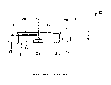
= Figure 1 shows a schematic diagram of a horizontal tube
resistance furnace set up for a sessile drop approach, as
described in Example 1;
= Figures 2A to 2F each depict a drop of slag and show in
sequence slag foaming for a graphite/slag system as a
function of time, using the horizontal tube resistance
furnace set-up of Figure 1;
= Figures 3A to 3F each depict a drop of slag and show in
sequence slag foaming for a coke/slag system as a function
of time, using the horizontal tube resistance furnace set-
CA 02578576 2012-05-07
- 7 -
up of Figure 1;
= Figures 4A to 4C respectively depict a drop of slag for
graphite, graphite/plastic and coke, each with a slag
system, and using the horizontal tube resistance furnace
set-up of Figure 1;
= Figure 5 shows a schematic diagram of a drop tube
furnace set up, as described in Example 4;
= Figure 6 shows an XRD spectra of a carbonaceous residue
from a 506 plastic and 50% graphite mixture after being
reacted in a drop tube furnace, as described in Example 5;
= Figure 7 shows CCD images of slag foaming caused by
various carbonaceous materials, as described in Example 5;
= Figure 8 shows the IR results for a reaction between a
graphite substrate and an industrial slag, as described in
Example 5;
= Figure 9 shows the IR results for a reaction between a
50% plastic and 50% graphite substrate and industrial
slag, as described in Example 5;
= Figure 10 shows the IR results for a reaction between a
coke substrate and an industrial slag, as described in
Example 5;
= Figure 11 shows a schematic diagram of an induction
(carbon dissolution) furnace, as described in Example 7;
= Figure 12 plots the % of carbon dissolution in a molten
ferro-alloy against time for the induction furnace of
Figure 11, and as described in Example 7;
= Figures 13 A&B depict a drop of coke/slag (upper row)
and coke/HDPE plastic/slag (lower row) over time, using
the horizontal tube resistance furnace set-up of Figure 1;
= Figure 14 plots the combustion efficiency, 11, of coke
and mixtures of coke with plastics at 1200 C, as described in
Example 9;
= Figure 15 shows CCD images of slag foaming as a
function of time for 70%coke- 30%plastic residue/slag
system at 1550 C, as described in Example 10;
= Figure 16 plots CO and CO2 gas generation as a
function of time, as described in Example 10;
CA 02578576 2012-05-07
- 8 -
= Figure 17 plots the number of moles of oxygen removed
during interactions of slag with coke and with
30%P1astic+70%coke mixture, as described in Example 10;
and
= Figure 18 shows the Vt/Vo plots for coke and
3096plastic+70%coke mixtures at 1550 C, as described in
Example 10.
Detailed Description of Specific Embodiments
During extensive studies of EAF steel production, it
was noted that the chemical reactions between solute
carbon/solid carbon and slag gave rise to the process of
slag foaming. Slag foaming occurred due to CO gas
generation as a result of the reduction of iron oxide in
the slag by carbon, and also due to the oxidation of
carbon. Slag foaming was noted to be strongly dependent on
the nature of the carbon feed material, with properties of
the material at high temperatures governing the slag
foaming phenomenon.
It was further noted that, as well as shielding the
electric arc, a foamy slag blanketed the metal bath and
held in heat, leading to considerable energy savings (ie.
reduced electricity consumption). It was noted that a
sustained level of slag foaming was critical to efficient
EAF steel production.
In a surprising development, it was postulated that a
un-agglomerated carbon-containing polymer (eg. waste
plastic, typically in particulate form) could be
introduced into EAF steel production. It was surmised
that, at the high temperatures employed in EAF steel
production, the waste plastic would, once introduced into
the furnace, combust (thus acting as a fuel) and produce a
carbonaceous residual product. Subsequently, it was
postulated that a carbon-containing polymer could also be
introduced into the production of other ferro-alloys and
again produce a carbonaceous residual product.
CA 02578576 2012-05-07
- 9 -
It was observed that the carbonaceous residual
product could then cause slag foaming in EAF steel
production, and might optionally function as a reducing
agent (eg. in the production of other ferro-alloys), and
optionally also function as a recarburiser.
During testing, it was hypothesised that the chemical
composition, structure and bond network in the original
plastic determined the properties of the carbonaceous
residue. In addition, it was noted that the kinetics of
carbon dissolution from a given plastic depended on the
rate at which the carbonaceous residue dissolved in liquid
steel. It was postulated that the relatively highly
ordered nature of carbon in plastics (eg. compared to
carbon in coke) could result in enhanced carbon
dissolution in liquid steel.
Structural characterisation of the carbonaceous
residues was conducted from a plastic-graphite mixture
introduced into a drop-tube furnace (simulating operating
conditions that might be experienced in an EAF) to observe
those carbonaceous residues that would subsequently lead
to foaming of liquid slag in an EAF, and to ascertain
those carbonaceous residues that might have a reduction
capacity and/or enhanced carbon dissolution in a molten
ferro-alloy. The structural characterisation results are
set forth below in Example 5.
In the production of other ferro-alloys it was noted
that a variety of carbonaceous reducing materials were
being used. Known reductant materials included carbons
such as coke, coal and char, and bio-carbons in form of
charcoal produced from different types of wood. Again, it
was noted that the material properties and reactions of
these carbonaceous materials played a significant role in
dictating reductant performance.
Major experimental considerations thus also included,
amongst others, investigations into gasification of the
reductant, dissolution of carbon into the molten metal,
and direct reduction of slag by solid carbon.
CD. 02578576 2012-05-07
- 10 -
The formation of slag was also noted to be typical in
the production of ferro-alloys other than steel. Manganese
and chromium were both reduced in solid and liquid states.
Dissolution of MnO in the slag followed by reduction from
the slag by solid carbon or carbon dissolved in liquid
metal was considered as the major mechanism of MnO
reduction. Similarly, reduction of chromite in liquid slag
by carbon dissolved in Fe-Cr melts was noted to be
important for the production of ferrochromium. The
reactions between carbon and liquid slag containing
dissolved ore (chromium, manganese oxides) played a vital
role in the reduction process. It was therefore postulated
that carbonaceous residues from waste plastics were also
able to be used as a reductant (and, as necessary, slag
foaming agent) in the production of other ferro-alloys.
Examples
Non-limiting examples of methods for producing a ferro-
alloy will now be provided.
Example 1
To investigate slag foaming, slag/carbon interactions
were first investigated in a laboratory scale, horizontal
tube resistance furnace 10, having an outer alumina tube
20, using the sessile drop approach. A schematic diagram
of the experimental set up is shown in Figure 1. The
weight of the slag used was -0.20 g. Initially, the slag
sample 22 was held on a specimen holder, in the form of an
alumina tray 24 with an alumina rod 26, which could be
pushed to the centre of the hot zone in the furnace with
the help of a stainless steel rod 28.
The slag/carbon assembly, in the form of the slag
sample 22 and graphite/coke substrate 30, was held in the
cold zone of the furnace until the desired temperature
(1550 C) was attained and equilibrated in the hot zone of
the furnace. The temperature was determined by
thermocouple 32. The assembly was inserted into the hot
CA 02578576 2012-05-07
,
- 11 -
zone at the desired temperature of study. This eliminated
any reaction that could occur at lower temperatures and
possibly influence the phenomena to be studied at the
temperature of interest. The furnace tube was purged with
argon, via gas inlet 34 and gas outlet 36, throughout the
duration of the experiment. The argon flow rate was
controlled by a mass flow meter.
The foaming behaviour of the slag/carbon system was
investigated using a closely controlled and visually
monitored sessile drop technique. A high quality, high
resolution charge-coupled device (CCD) camera 38 fitted
with an IRIS lens was used to capture the live in-situ
phenomena in the furnace, viewed through quarts windows
40. The output from the camera was channelled to a video
cassette recorder (VCR) 42 and a television (TV) monitor
to record the entire process as a function of time. This
allowed specific images, displaying the contact between
the slag and carbonaceous material, to be captured as a
function of time, from the videotape into a computer 44
using a frame grabber. A time-date generator 46 was used
in the system to display the duration of the process.
Specially designed computer software was used to determine
the volume from the captured images, on the basis of a
curve-fitting exercise. For a better understanding of
reaction dynamics, images were recorded for up to 2 hours
in most cases.
The slag composition was as follows: CaO 30.48%, MgO
11.72%, Si02 13.3496, A1203 5.24 %, Fe203 33.33%, MnO 5.24%.
Slag foaming investigations were first carried out on
graphite and coke. Slag foaming investigations were later
carried out on plastic.
Results & Discussion
Graphite/slag system: Preliminary results on slag foaming
in a graphite/slag system are shown as a function of time
in Figures 2A to 2F.
CA 02578576 2012-05-07
- 12 -
Graphite showed good foaming characteristics with a
steel production slag. In Figure 2A at T=13 sec, the slag
powder is shown as just beginning to melt. In Figure 2B
the drop of liquid is shown taking shape at T=47 sec and
in Figure 2C is shown completely formed at T=57 sec. The
droplet then begins to grow in size, with increasingly
larger drops being observed in Figure 2D at T=lmin 7 sec,
and in Figure 2E and at T=lmin 22 sec, indicating that
slag foaming is taking place. In Figure 2F at T= 1 min. 57
sec, the droplet has collapsed slightly indicating the
partial escape of some gaseous products. Thus, the slag
foaming in a graphite/slag system was found to be quite
rapid and extensive.
Coke/slag system: Preliminary results on slag foaming in a
coke/slag system are shown as a function of time in
Figures 3A to 3F.
Coke showed less reliable foaming characteristics
with a steel production slag. In Figure 3A at T=9 sec, the
slag powder is shown as just beginning to melt. In Figure
3B the drop of liquid is taking shape at T=1 min 20 sec.
In Figures 3C to 3F, images ranging from T= 2 min 15 sec
to T=21 min 37 sec are shown. Over this time period the
liquid drop is completely formed. The four drops show
minor fluctuations in size and volume, indicating a rather
small level of slag foaming in the coke/slag system. The
rate of slag foaming in the coke/slag system was thus
slower than the graphite/slag system.
Carbon dissolution studies revealed that the
dissolution rate constant for coke was smaller than that
for graphite. The slag foaming behaviour of these two
carbon types was quite different, with the rate and extent
of slag foaming in the graphite/slag system being much
higher than the coke/slag system. Thus, a relationship
between carbon dissolution rate and slag foaming was
postulated.
CA 02578576 2012-05-07
- 13 -
Example 2
An analysis of plant operating data from an operating
EAF showed that increasing levels of coke injection
resulted in increased consumption of oxygen, although they
did not yield any well-defined pattern in power
consumption per ton of steel charged.
The operating EAF used two different forms of carbon
in its operation. Along with coke containing - 90% C, it
used a few tons of flat iron containing 4% C. Carbon
present in the flat iron was already dissolved when the
flat iron melted, whereas carbon present in the coke was
present in a solid state.
The form of carbon (solute or solid carbon) was
observed to have a significant effect on average power
consumed/ton of steel. With an increased amount of flat
iron charged (equivalent to higher levels of solute
carbon) there was a significant reduction in power
consumption. This trend was interpreted in terms of the
role played by the carbonaceous material and indicated
that an increase in slag foaming lead to a decrease in
power consumption, per ton of steel charged. The
efficiency of flat iron carbon in EAF steel production was
thus found to be much higher than the corresponding
efficiency for coke.
The inventors noted that:
1. The kinetics of carbon dissolution into liquid iron
depended strongly on the nature of carbonaceous material.
For example, the dissolution rate constant for coke was
smaller than that for graphite.
2. The results of the graphite/slag and coke/slag systems
of Example 1 showed that the rate and extent of slag
foaming with graphite was much higher than coke.
3. The kinetics of carbon/slag interactions are expected to
be quite different for solute carbon and for coke, which
resulted in wide variations in their slag foaming
behaviour.
CA 02578576 2012-05-07
- 14 -
These results indicated that an appropriate choice of
carbonaceous material could play an important role in slag
foaming and therefore in the energy efficiency of EAF
operation. The results also lead the inventors to surmise
that a carbon-containing polymer could be added to an EAF
and partially combust as a fuel and to produce
carbonaceous material residues, which could give rise to
slag foaming and/or metal oxide reduction and/or
recarburisation.
Example 3
The inventors now tested the addition of waste
plastics to an EAF process in place of at least some of
the traditional source of carbon (eg. coke). The following
raw materials were assembled to simulate the raw materials
fed to an EAF.
Raw materials
The following carbonaceous materials, plastics and
slag were employed to conduct comparative slag foaming
experiments.
Carbonaceous materials: graphite; coke; residue generated
from a mixture (1:1) of graphite and plastic (the XRD
spectrum of this residue is provided in Figure 6). The
ratio of 1:1 may vary from furnace to furnace.
Plastic material: Linear Low Density Polyethylene (LLDPE)
was obtained to represent the major constituent of plastic
waste. Particle sizes of polyethylene samples used were
less than 100 micrometers.
Slag: The following slag composition (%wt) was prepared:
30.48% CaO; 11.72% MgO; 13.34% Si02; 5.24% A1203; 33.33%
Fe203; 5.24% MnO.
A substrate of carbonate material powders were
prepared by hydraulic pressing under a pressure of 2.2x10⁸
Pa. The graphite and coke powders were used as supplied.
The preparation process of the graphite and plastics
mixture is described in Example 4.
CA 02578576 2012-05-07
- 15 -
The slag was prepared by heating the homogeneous
mixture of oxide ingredients in the mixing ratio shown
above to 1650 C, and then casting the melt in a copper mold
after around 30 min from complete melting.
Apparatus
The horizontal furnace of Figure 1 was used for
carrying out sessile drop experiments. The dimension of
the ceramic furnace tube was 050 mm inner diameter and
1000 mm in length. A specimen holder made of alumina or
graphite was inserted into the tube through a furnace
cover. The apparatus permitted the sample to be held in
the cold zone of the furnace before the furnace was heated
up to the desired temperature, typically 1550 C in this
Example.
Experimental procedure
To investigate slag foaming, slag/carbon interactions
were first investigated in the horizontal tube resistance
furnace. The slag/carbon assembly was held in the cold
zone of the furnace until the desired temperature (1550 C)
was attained and equilibrated in the hot zone of the
furnace. The assembly was then inserted into the hot zone
at the desired temperature. This procedure eliminated any
reaction that could occur at lower temperatures and
possibly influence the phenomena to be studied at the
temperature of interest. The furnace tube was purged with
argon throughout the duration of the experiment.
The foaming behaviour of the slag/carbon system was
again investigated using a closely controlled and visually
monitored sessile drop technique. Again the CCD camera
fitted with an IRIS lens was used to capture the live in-
situ phenomena in the furnace. Again the output from the
camera was channelled to a VCR and TV monitor to record
the entire process as a function of time. The images
displaying the contact between the slag and carbonaceous
material were captured over time, from the videotape and
into a computer, using a frame grabber. Again the time-
date generator was used to display the duration of the
CA 02578576 2012-05-07
- 16 -
process. Computer software determined the volume from the
captured images, on the basis of a curve-fitting exercise.
Slag powder (approximately 0.20g) was placed on the
carbonaceous materials substrate, which was held on the
specimen holder. Once the desired furnace temperature was
reached the specimen holder was pushed from the cold zone
to the hot zone of the furnace to start the experiment.
The whole reaction process was monitored by the CCD camera
and recorded using video-tape. The images were analyzed
further to calculate sample volume. Throughout the
experiment, inert gas argon was flown at a flow rate of 1
1/min. The off-gas was passed through an IR analyzer in
order to obtain CO and CO2 content, which can be used to
evaluate the reaction rate.
Experimental results
The experiments were conducted to investigate the
slag foaming behaviour caused by the reaction between iron
oxide in slag and the carbonaceous materials: graphite,
graphite/plastic residue mixture, and coke. Typical images
are shown in Figures 4A to 4C.
The reaction between graphite and slag was observed
to produce the most vigorous slag foaming. The volume of
the drop of foamed slag was the largest as clearly shown
in the Figure 4A.
During the reaction of the 50% graphite/50% plastics
mixture, bubbles evolved from the slag droplet. The
occurrence of slag foaming phenomenon in the case of the
graphite/plastics mixture was established on the basis of
a high temperature visualisation image as shown in Figure
4B and also on the basis of generation of CO in the off-
gas, indicating a reduction of iron oxide. This indicated
that plastics could be added to an EAF, combust as a fuel,
and the carbonaceous residues could produce slag foaming
and/or metal oxide reduction and/or recarburisation
effects.
CA 02578576 2012-05-07
- 17 -
Example 4
Preparation process of graphite/plastics mixture
A high temperature gas-phase reaction of a plastic-
graphite blend was performed using a drop tube furnace
(DTF) 50. The drop tube furnace, shown schematically in
Figure 5, has an alumina tube 52 surrounded by heating
elements 54 and insulation 56. The temperature of the
furnace is monitored by a thermocouple 58 located inside
the furnace and a thermocouple 60 located outside the
furnace.
Each trial conducted in the DTF 50 was completed at
1200C and, once the furnace had reached this operating
temperature, determine via inside thermocouple 58, oxygen
and nitrogen gases 62 were introduced into the furnace at
desired flow rates. Gas flow rates and compositions were
controlled during these experiments using an automated
flow controller and exhausted via vent 64 as required.
Cooling water 66 was circulated through the furnace
injector, or feeding probe 68, during each test so as to
prevent overheating and the occurrence of reactions prior
to the interaction of oxygen and the injected fuel
materials in the furnace reaction zone 70. The sample
collector 72 also served the purpose of retaining unburnt
chars generated during each experiment.
A plastic-graphite blend 74 was introduced into the
experimental reactor 50 using a dry material, or screw,
feeder 76 through a water-cooled feeding probe 68. A
mixture of oxygen and nitrogen gas was used to carry the
plastic and graphite solid reactants into the reaction
zone 70. The experimental details were as follows:
Temperature ( C) 1200
Total gas flow rate
1.0
(L/min)
Feeding rate (g/hr) 10.0
Particle residence time
- 1-2
(seconds)
CA 02578576 2012-05-07
- 18 -
Gas purity (%) N2 = 99.5
02 = 99.0
Gas composition 24% 02, rest N2
Graphite particle size < 100pm
Plastic particle size < 100pm
This experiment indicated that, under operating
conditions that may simulate those in an EAF, the plastic
could be charged into an EAF, combust as a fuel, and form
carbonaceous residues useful for causing slag foaming,
metal oxide reduction and in recarburisation of molten
iron.
Example 5
EAF slag foaming phenomenon accompanying the reaction
between slag and carbonaceous materials
Experiments were carried out to study an actual EAF
slag sample, more particularly, the slag foaming phenomena
during the reaction between the slag and carbonaceous
substrates under an inert argon atmosphere. The slag
composition was 27.0% CaO; 40.3% FeO; 7.9% A1203; 8.8% MgO;
10.9% Si02; and 4.8% MnO. The basicity of the slag was 2.5
(tCaO/tSi02). Three carbonaceous materials were chosen for
the experiments. They were pure graphite; a carbonaceous
residue from a mixture of graphite and plastic with a
mixing ratio of 1:1; and industrial coke. The ratio of 1:1
may vary for different EAF's. Around 0.075g slag was used
for each run. The temperature was set at 1550 C.
Figure 6 shows the XRD spectrum of the residue
generated from 50% plastic and 50% graphite mixture after
being reacted in a drop tube furnace (DTF). The peaks of
plastic and graphite can be clearly seen.
The slag/carbon foaming phenomenon was recorded using
a CCD camera. Figure 7 shows the typical images of foamed
slag drops reacting with various carbonaceous substrates
at the time of approximately 200 secs. Slag foaming was
most vigorous in the case of reaction with graphite
CD. 02578576 2012-05-07
- 19 -
substrate. Although the reaction between slag and coke and
a mixture of plastic and graphite was not as vigorous, the
results indicated that plastic could act as both slag
foaming agent and reductant with EAF slag.
The CO and CO2 contents in DTF off-gas were analyzed
using an IR analyzer. The results are shown in the
following Figures 8, 9 and 10. In the case of a graphite
substrate, the off CO and CO2 gas contents were only
slightly larger than the other cases. This implied that
gas evolution due to a reduction of iron oxide was
occurring with all three carbonaceous materials and all
three were contributing to slag foaming.
In addition, the results of Example 5 are in
agreement with the results of the previous Examples,
notwithstanding the difference in composition between the
industrial slag and laboratory prepared slags.
Example 6
The combustion efficiency of waste plastics was
investigated to test the suitability of waste plastics as
a fuel in an EAF or other non-blast-type furnace. The
combustion efficiency was evaluated using the drop tube
furnace (DTF) of Figure 5 using the same conditions as in
Example 4. The WC in the samples was determined before
and after each test run (ie. after each sample was passed
through the DTF). A LEM carbon content analyser was used
for determination of carbon content.
Each sample comprised varying levels of powdered
waste plastic mixed with powdered coke, starting from 0
wt W plastic and moving up to 50 wt% plastic. The results
are presented in the following table:
Plastic wt W C wt W C wt t Combustion
with coke before after Efficiency (W)
0 80.43 80.39 0.25
20 82.376 80.921 9.26
30 82.79 81.736 6.97
83.723 82.27 9.79
84.372 83.145 8.63
CA 02578576 2012-05-07
- 20 -
The table lists the resulting combustion efficiency
(last column), and also lists a raw wt %C analysis. The
decrease in wt %,C is as a result of the carbon reacting
(combusting) to produce carbon monoxide and dioxide gas.
The results show that the combustion efficiency of
coke is very poor, but when waste plastics are mixed with
the coke the combustion efficiency is increased. In
addition, the residue that is left after combustion then
participates in other reactions in the EAF or other non-
blast-type furnace.
Example 7
To investigate the function of waste plastics as a
recarburiser in ferro-alloy production, carbon dissolution
of a carbonaceous reside was investigated in a laboratory
scale induction furnace 80 as schematically depicted in
Figure 11.
The temperature of the furnace 80 was controlled to
achieve a molten iron bath temperature of 1550 C (to
simulate an EAF operating temperature). In this regard,
cooling water 82 was circulated through a "jacket" heat
exchanger configuration surrounding the furnace crucible
84 during the procedure so as to prevent overheating and
to maintain a generally constant bath temperature. A
nitrogen atmosphere was created above the molten bath 86
via the N2 gas inlet 88.
A powder of waste plastic was fed directly into the
furnace, the powder feeding onto the molten iron bath 86.
This plastic combusted to produce a carbonaceous residue,
which residue could function as a recarburiser. As an
alternative, waste plastic from eg. the drop tube furnace
of Figure 5 could be introduced onto the molten iron bath.
The carburiser cover method was the standard approach
used to study carbon dissolution. In this regard, the
carbonaceous material actually sat on top of the metal
bath and formed a carburiser cover 90. This is because,
ak 02578576 2012-05-07
- 21 -
in the experimental procedure, waste plastics material is
fed onto the top of the metal bath 86. A thermocouple 92
to measure bath temperature together with a quartz
sampling tube 94 for removal of metal samples to
progressively measure carbon dissolution over time,
extended through the carburiser cover 90. The LECO carbon
content analyser was then used to analyse the carbon
content of metal samples extracted.
The results of carbon dissolution are presented in
Figure 12. In Figure 12 it can be seen that initially
(Time = 0) the bath had a dissolved carbon content by
weight of 1.67%. Plastic residue was then added and the
dissolved carbon content increased to 2.97%, and then
levelled out at around the 3% level. At Time = 25 minutes,
further plastic residue was added to the bath and the
dissolved carbon content increased to 3.89% at T = 30
minutes.
This experiment demonstrated that the plastic residue
could be used as an effective recarburiser, and that
progressive increased levels of dissolved carbon could be
achieved with progressive introduction of plastic residue.
In an EAF or other non-blast-type furnace, the residue for
recarburisation would typically be generated by
introducing the waste plastic itself into the furnace,
allowing it to combust to produce a carbonaceous residue,
and then facilitating its mixing into the molten metal
bath and allowing it time to increase carbon content to a
desired level. The waste plastic can replace more
expensive recarburisers such as anthracite coal and
graphite.
Example 9
Combustion efficiency of Coke/Plastics mixtures
Coke and its mixtures with plastics (up to 50 wt%)
were burnt in the DTF at 1200 C in an oxidising atmosphere
containing 20% 02. The feeding rate was around 0.0278 g/s.
Carbonaceous residues were collected and their carbon
CD. 02578576 2012-05-07
=
- 22 -
content was measured. Assuming a negligible loss of ash
during combustion in DTF, the combustion efficiency, n,
was calculated as:
A C
= (1 ¨ -)x 100 Vo
Ai CO
where Ao and Ai were ash content before and after
combustion, Co and Ci respectively represented carbon
content before and after combustion in DTF, respectively.
Experimental results on the combustion efficiency of
coke/plastics mixtures are shown in Figure 14. A
logarithmic scale was used along the y-axis due to the
large variations in combustion efficiency.
In this example overall combustion efficiency of the
coke/plastics mixtures was observed to be nearly forty
times the combustion efficiency of coke alone, i.e. -10
for coke-plastics mixtures as against 0.25 for coke.
Higher combustion efficiency of coke/plastics mixtures
could be, to a certain extent, attributed to a large
release of volatiles during combustion of plastics. Whilst
the mixtures of coke and plastics generally had much
higher combustion efficiency than coke, no well-defined
trend was observed on the effect of mixing ratio. However,
no degradation in the combustion efficiency was observed
with increasing plastic component.
Example 10
Slag foaming on carbonaceous residues
Carbonaceous residues from mixtures of coke and
plastic after burn-off in the DTF were pressed into a die
under 9 tonnes/cm2 load and were used as a substrate for
slag foaming experiments. After reaching desired
temperatures, the slag began to melt and the iron oxide
ak 02578576 2012-05-07
- 23 -
present in the slag started reacting with the carbonaceous
substrate to give off CO and CO2 gases and metal iron. The
evolution of CO and CO2 gases through the slag phase lead
to slag foaming. The reaction process was monitored using
CCD camera and recorded to DVD disc for further image
analysis. Figure 15 shows the typical images of a reaction
between a slag and a mixture of 30%plastic+70%coke. After
the slag melt down, gas bubbles were observed to evolve
through the slag phase immediately. The slag droplet
rolled around on the substrate vigorously due to the
generation and rupture of the gas bubbles. After about 600
secs, the slag droplet calmed down gradually with a
considerable reduction in gas generation.
Also, during the reaction between the slag and
coke/plastic substrate, FeO in the slag and C in the
substrate reacted to generate CO and CO2 gas. The
concentrations of these gases are measured in the off-gas
mixture using an IR spectrometer.
The resulting typical CO and CO2 gas contents are
shown in Figure 16. It can be seen that both the CO and CO2
gas contents increased sharply to maximum values,
stabilised for nearly 300 seconds and then decreased with
reaction time. Much less CO2 gas was detected in the off-
gas than CO. The volume of CO and CO2 evolved obtained from
the off-gas analysis were then converted into the number
of moles using the standard gas equation. The number of
moles of oxygen removed reflected the kinetics of
reduction reactions between slag and carbonaceous
material, as shown in Figure 17.
The results indicated that the reduction reactions of
slag with coke were much faster than the corresponding
reactions with plastic-coke mixture, resulting in a larger
volume of emitted gases. These gases give rise to slag
foaming and caused changes in the volume of the slag
droplet.
Gas hold-up in the slag droplet was then measured in
terms of Vt/Vo, where Vt is the volume of slag droplet at
CA 02578576 2012-05-07
- 24 -
time t and Vo is the initial volume. Figure 18 plots Vt/Vo
as a function of time for coke and 30%plastic+70%coke
mixture. The results showed that much higher levels of
slag foaming were observed for 30% plastic + 70% coke
mixtures as compared to coke. The droplet grew much larger
in size in the case of coke/plastic mixture and this size
increase was sustained for a much longer period for the
plastic mixture as compared to coke. To a great extent,
this could be due rather slow rate of reactions between
the plastic mixture and slag (Figure 17), resulting in a
slow rate of gas emission, thus resulting in smaller
bubbles and a sustained foam over longer periods. For
coke, the bubble growth was rapid with high gas levels
escaping from the slag droplet.
The Example 9 and 10 investigations on coke and a
range of coke/plastic mixtures further demonstrated the
feasibility of utilising waste plastics in EAF
steelmaking. Coke/plastics mixtures showed much better
combustion than pure coke. The slag foaming
characteristics of coke/plastics mixtures were found to be
better than pure coke. The slag droplet showed a much
larger increase in volume, and the volume change was
sustained over a longer period of time. The results also
indicated that partial replacement of coke with
coke/plastic mixtures could enhance carbon combustion.
Example 11
In an experimental procedure similar to that
described in Example 3 and as depicted in Figure 4, the
foaming characteristics of a coke/slag system and a 50%
coke/50% plastic/slag system were investigated. In this
case, the plastic was a High Density Polyethylene (HDPE),
with a particle size of less than 100 micrometers. The
slag was similar to that of Example 5 and 0.078 grams and
0.092 grams of slag were respectively employed for the two
systems. The runs were conducted at different times,
hence the weights of slag are not exactly the same.
CA 02578576 2012-05-07
- 25 -
However, this weight difference does not affect the
experimental outcome.
Figures 13A&B depict in side by side comparison the
drop foaming behaviours of the two systems at the time
intervals 0, 30, 45, 60, 90, 150, 210 and 300 seconds. It
can be seen that the coke/plastic/slag system had a
relatively more rapid foaming characteristic than the
coke/slag system.
In other words, plastics such as HDPE can also offer
an enhanced slag foaming characteristic to an EAF or other
non-blast-type furnace, indicating that many other
plastics may offer a similar enhanced performance.
Example 12
The inventor conceived of and proposed an index to
indicate the suitability of a plastic for its re-use in
ferro-alloy production and as a combustible fuel in other
non-blast-type furnaces. The index was referred to as the
Green Index for Plastics (or "GIP" index). The inventor
conceived that the index could also be used in a general
sense as relating to recyclability of plastic, and yet
still be known as the GIP index.
In this way, a mechanism could be established by
which the general public could recognise the ability of a
plastic to be recycled, for example in ferro-alloy
production such as steelmaking. The inventor noted that
the current system used for identification of plastics
type, does not provide any information regarding the
plastic's recyclability. The current system merely
provides information regarding the type of plastic (eg
numeral 1 for PET etc).
Finally the inventor surmised that the GIP index
could then be built upon by developing a related GIPS
index, where the "S" stands for and indicates the
suitability of the plastic for use in steelmaking.
In general, the experiments also indicated, that for
the production of ferro-alloys other than steel, and using
CA 02578576 2012-05-07
- 26 -
an EAF, un-agglomerated plastic could be charged into the
furnace, could combust as a fuel, and could form
carbonaceous residues useful for slag foaming, and to
cause metal oxide reduction, and recarburisation of molten
metal (eg. iron).
In addition, the experiments also indicated that for
reheating furnaces and the like, the un-agglomerated
plastic could be charged into the furnace, for example as
a supplement to other fuels such as natural gas, and yet
still combust as a fuel. This is especially so at the
higher temperatures (greater than 1000 C) used in furnaces
such as reheating furnaces in steel forming operations.
Thus, an effective means for using and consuming the
vast quantities of waste plastics in society is provided.
Whilst a number of specific embodiments have been
described, it should be appreciated that the method for
producing a ferro-alloy can be embodied in many other
forms.