Note: Descriptions are shown in the official language in which they were submitted.
CA 02578713 2007-02-14
CNZZO1-02CA
1
METHOD AND APPARATUS FOR TREATING SLEEP APNEA AND SNORING
TECHNICAL FIELD
[0001] Embodiments of the present invention relate to an apparatus for
treating snoring
and obstructive sleep apnea, or either of them, and also relate to a method of
treatment of these
conditions, using electrical stimulation.
BACKGROUND
[0002] Snoring is a condition commonly caused by a partial obstruction of the
upper
airway, in which the airflow causes the obstructing tissue to resonate,
resulting in
characteristic and well known snoring sounds. Snoring can be a major
disruptive agent in
relationships where one person is subjected to sleep disturbing effects, which
the snoring
partner causes.
[0003] Obstructive sleep apnea is a more serious medical condition caused by a
more
pronounced obstruction such that the airflow during breathing is severely
restricted or is
completely interrupted. This condition causes a degraded sleep pattern and
reduced blood
oxygenation and is believed to have the potential for producing serious
medical problems,
including cardiovascular complications.
[0004] Various solutions are well known for treating upper airway
obstructions. Some of
these solutions involve an insertion of mechanical devices, or even surgical
interventions.
Subjecting the airway to a constant pressure of a few millibars by means of a
mask connected
to a pressurized air source (a technique known as Continuous Positive Airway
Pressure) is a
proven method of controlling sleep apnea. However, these techniques are
invasive and
therefore persons are reluctant to use them.
[0005] Other less invasive techniques are known in which the onset of the
obstructive
condition is detected and a stimulus is applied to disturb the person, in
order to elicit a
response in which the condition is corrected. Examples of devices and
techniques belonging
to this class are shown in U.S. Patents Nos. 3,480,010 and 4,715,367 issued to
Crossley; U.S.
Patent No. 3,696,377 issued to Wall; U.S. Patent No. 4,220,142 issued to Rosen
et al.; U.S.
Patent No. 4,593,686 issued to Lloyd et al.; U.S. Patents Nos. 6,666,830 and
6,935,335 issued
CA 02578713 2007-02-14
CNZZ01-02CA
2
to Lehrman et al. and U.S. Patent No. 6,371,120 issued to Chiu et al. These
devices operate by
a variety of techniques which have in common two aspects; firstly, detection
of the obstructed
airway condition (either snoring or sleep apnea), and secondly, applying a
stimulus to the
subject in respect to such detection.
5[0006] Recent research has shown that obstructions in upper airways may be
cleared with
electrical stimulation. Two articles describing this research may be found in
American
Review of Respiratory Disease, Vol. 140, 1989 at pp. 1279-1289. The first
article is entitled
"Effects of Electrical Stimulation of the Genioglossus on Upper Airway
Resistance in
Anesthetized Dogs" by Hiroshi Miki et al. The second article is entitled
"Effects of
Submental Electrical Stimulation During Sleep on Upper Airway Patency in
Patient with
Obstructive Sleep Apnea" also by Hiroshi Miki et al. U.S. Patent No. 4,830,008
issued to
Meer discusses an implantable system for treatment obstructive sleep apnea by
means of
electrical stimulation. A system achieving the same goal by the same means
without resorting
to implantation is discussed in U.S. Patent No. 5,265,624 issued to Bowman. In
this system
electrodes are placed on the gums, thus in the immediate vicinity of the
genioglossus and
related muscle groups in the upper airway, by means of a mouthpiece fitted
with passive
circuitry energized by radio frequency emitted by a collar assembly which
incorporates the
power supply and event detector. Radio frequency is processed within the
mouthpiece in
order to power the circuit and issue a train of narrow unidirectional pulses
to the stimulating
electrodes. Although not made evident in the writing, unidirectional pulses
are effectively
integrated into a direct current by storage components of capacitive and
electrolytic nature
intrinsic of the circuit pathway. Thus Bowman also relies on DC stimulation of
the muscles of
interest.
[0007] A disadvantage of the prior art devices is that there is a substantial
likelihood that
the stimulus they apply to the subject will degrade the subject's sleep
quality. This negates the
primary objective of restoring a restful sleep to the subject. Also, subjects
are deterred from
using user unfriendly, cumbersome contrivances such as that proposed by
Bowman.
CA 02578713 2007-02-14
CNZZOI-02CA
3
SUMMARY
[00081 An apparatus for treating an obstruction of the upper airway of a
person, such
condition causing an episode of either snoring or obstructive sleep apnea,
comprises:
a) a sensor for sensing the onset of said episode;
b) a stimulus generator coupled to said sensor and responsible thereto for
generating a stimulation signal for application to said person, said signal
comprising a direct
current and a pulsating current;
c) said generator including a circuit activated upon the sensing of said
episode for
regulating the relative levels of said direct current and of said pulsating
current as said
stimulation signal is applied to said person; and
d) a sensor for detecting the end of said episode and being coupled to said
generator for terminating the application of said stimulation signal to said
person following the
end of said episode.
[0009] A method of treating a person having an obstruction of the upper airway
causing
the onset of either a snoring or an obstructive sleep apnea episode comprises:
a) sensing the onset of said episode;
b) upon the detection of said onset, applying an electrical stimulation signal
to
said person, said signal comprising a direct current and a pulsating current;
c) regulating the relative levels of said direct current and said pulsating
current as
said signal is applied to said person;
d) sensing termination of said episode; and
e) following sensing said termination, terminating the application of said
stimulation signal to said person.
CA 02578713 2007-02-14
CNZZOI-02CA
4
BRIEF DESCRIPTION OF THE DRAWINGS
[0010] Embodiments are illustrated by way of example and without limitation in
the
figures of the accompanying drawings, in which like reference numerals
indicate
corresponding, analogous or similar elements, and in which:
5[0011] Fig. 1 is a plan view of the inner front part of a neck strap, which
supports
components of a system according to the invention;
[0012] Fig. 2 is a side sectional view of an electroacoustic transducer;
[0013] Fig. 3 is a block diagram of a detection circuit which detects snoring
and sleep
apnea episodes; and
[0014J Fig. 4 is a block diagram of a stimulus generator.
CA 02578713 2007-02-14
CNZZO1-02CA
DETAILED DESCRIPTION
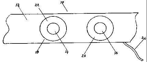
[0015] Reference is made to Fig. 1, which is a plan view of the inner front of
a neck strap
for use with embodiments of the present invention. The neck strap 10 includes
a main
substrate 12 of woven material with a sufficiently open weave to allow for
evaporation of skin
5 moisture. The neck strap 10 supports conductive stimulation pads 14, 16 in
spaced apart
relation, an electroacoustic transducer 18 comprising an acoustic sensing
diaphragm 22 and a
conductive stimulation pad 14, and an insulating disc 20 which carries
conductive stimulation
pad 16. The output of transducer 18 and conductive stimulation pads 14, 16 are
connected to
the supporting circuits for use with embodiments of the present invention by
means of cable
10 24. Cable 24 also carries stimulation signals to conductive stimulation
pads 14 and 16. The
neck strap 10 does not need to apply more than a gentle pressure on the skin,
since the
stimulation circuit path is of high impedance value at the source, to minimize
the effects of
such variables as resistance at the pad-skin interface and others of
physiological nature.
[0016] Fig. 2 is a side section view of electroacoustic transducer 18, which
includes
supporting structure 26 made of insulating plastic such as polycarbonate. The
front of
transducer 18 carries acoustic sensing diaphragm 22 made of thin polyamide
foil or other
material with similar mechanical electrical specifications. Diaphragm 22 is
bonded at the
periphery to the flat rim of supporting structure 26 and it carries conductive
stimulation pad
14, pad 14 being in the form of a disc made of thin stainless steel foil
bonded to diaphragm 22
at the centre of diaphragm 22. A thin conductive wire 30 connects pad 14 to
terminal 32 on
the back of the supporting structure 26. Air cavity 38 is the site where an
acoustic pressure is
generated by diaphragm 22 when diaphragm 22 is vibrating in response to
acoustical events
such as breathing airflow and snoring, by virtue of being positioned in
intimate contact with
the skin of the throat. The acoustic pressure is converted into an electrical
signal by
microphone 34, which is affixed with a sealing bond in a centre hole of
supporting structure
26. A shielding disc 36 is an electrostatic shield which prevents stimulation
pulses present on
pad 14 from interfering with the minute signal output by microphone 34.
Shielding disc 36 is
mechanically supported by three or four wires 40 which have also electrically
connect disc 36
to ground ring 42 which is the ground reference of the circuit. This
connection further aids in
making the output of microphone 34 free of interference. Terminal 44 is the
output
connection of microphone 34.
CA 02578713 2007-02-14
CNZZO1-02CA
6
[0017] Fig. 3 is a block diagram of a detection circuit which detects snoring
and sleep
apnea episodes. In the detection circuit the signal from microphone 34 is
amplified by
amplifiers 50, 60 and then applied in two branches to bandpass filters 52, 62
which extract
telltale signatures respectively of breathing and snoring activity. Various
types of signal
processing are well known to those skilled in the art to detect breathing
activity and snoring
activity and to filter out extraneous signal components. The snoring signal is
directed to full
wave rectifier 64 and then to internally referenced comparator 66, which
outputs a logic one if
snoring is sensed.
[0018] The breathing signal from bandpass filter 52 is rectified by full wave
rectifier 54,
the output of which is directed to internally referenced comparator 56 which
outputs a logic
one if the acoustic signature of air flow is detected. The output of
comparator 56 is used to
reset a timer 58, the output of which is set to go high after an interval of
four to six seconds
following any reset. Respiration cycles are typically four to six seconds and
therefore the
timer 58 is reset every equivalent time interval (i.e. every respiration
cycle). Thus the timer 58
will output a logic one if a breathing pattern is not detected for more than
six seconds. The
range of four to six seconds is suggested as from experimentation this appears
to be the
optimal range for effective use of embodiments of the present invention.
However it is not the
intent of the inventor to restrict embodiments of the invention to this range,
other ranges may
be utilized if found to be effective.
[0019] Snoring events are characterized by a logic one at the output 74 and
apnea events
by a logic one at output 70. Outputs 70, 74 are directed to the inputs of OR
gate 68, which
outputs at 72. The information present at points 70, 72, 74 is directed to the
processing
circuits of the stimulus generator illustrated with reference to Fig. 4.
[0020] Fig. 4 is a block diagram of a stimulus generator. Astable oscillator
78 is set
running by a logic one at the output of OR gate 76. The frequency of astable
oscillator 78 is
controlled by means of variable resistor 80 within a range of approximately
three to 10 pulses
per second. The output of astable oscillator 78 is directed to a Schmitt
trigger 86, via a
resistor-capacitor network of capacitor 82 and variable resistor 84, with a
time constant in the
range of fifty microseconds to fifty milliseconds. The output of Schmitt
trigger 86 is a train of
pulses with a width equivalent to the time constant of the input network. The
pulse train
issued by Schmitt trigger 86 is directed to level risetime control 88, which
sets the amplitude
CA 02578713 2007-02-14
CNZZOI-02CA
7
of the pulses at a pre-selected value. On one embodiment the time for pulse
amplitude to
reach the pre-selected value is made to be within 1 second after the sensing
of a snoring event
and seconds following the sensing of an apnea event, the information being
supplied by apnea
and snoring information present at points 70 and 74 respectively. The output
of level risetime
control 88 is directed to output driver 90, which also converts the
unidirectional pulses at its
input into symmetrical square waves, which are then applied to the primary of
step-up
transformer 92. Thus square waves with the required high voltage are present
at the secondary
winding of transformer 92.
[0021] HV inverter 94 raises the power source voltage to the level required
for
stimulation. As one skilled in the art can appreciate any number of power
sources may be
used to power the circuitry of embodiments of the present invention, a battery
being one such
example. The time for the voltage to reach a maximum value is set by DC level
risetime
control 96. In one embodiment the time would be three seconds after the onset
of an apnea
event and zero seconds after the onset of snoring, this being accomplished by
pertinent
information at points 70, 74 applied to level risetime contro196. Maximum
level is set by DC
max level control 98 which in one embodiment reduces the level by 50% if
snoring
information is present at point 74.
[0022] DC at the output of level control 98 is directed to polarity control
unit 106 via the
secondary of transformer 92, which is connected in series in the stimulation
circuit. A
stimulation signal thus consists of a DC current with a square wave pulse
train superimposed
on it, the balance between the two modes being apt to be adjusted as required.
This composite
signal is directed to conductive stimulation pads 14, 16 via polarity control
106, which assigns
ground level and high level to either one depending on the output status of
FLIP-FLOP 104
which is clocked by apnea or snoring information at point 72. Thus the
polarity applied to
conductive stimulation pads 14, 16 is reversed at every new episode of
stimulus generator
operation, this being done to counteract effects of a constant polarity DC
current such as
electrolytic effects at the pad-skin interface and possible increase of the
threshold of
stimulation level.
[0023] Following the onset of a snoring episode, characterized by a logic one
at point 74
which starts astable oscillator 78 by means of OR gate 76, pulse stimulation
is applied to the
subject with the level reaching maximum in one second, the level rise being
interrupted at the
CA 02578713 2007-02-14
CNZZO1-02CA
8
point which causes the event to cease. Following the onset of a snoring
episode DC
stimulation is also applied to the subject, with a level reaching 50% of a pre-
set maximum
with no delay. DC stimulation is also interrupted at a level where the
condition is interrupted.
Reason for such process is that while DC stimulation acts to open the airway
with a minimum
of perceived effect by the subject, pulse stimulation is perceived as a tingle
evoking a
condition in which the event is terminated. Said perceived stimulus has the
effect of
conditioning the subject into subconsciously avoiding a posture conducive to
snoring. The
sudden application of a reduced DC level also contributes to perception.
[0024] Following the onset of an apnea episode, characterized by a logic one
at point 70
which activates HV inverter 94, DC stimulation is applied to the subject, the
level of which
reaches a pre-selected maximum value in three seconds after the onset of the
episode.
Stimulation is interrupted at the level which causes the event to cease. If
the episode is not
corrected at maximum DC stimulation level, which is characterized by a logic
one at the
output of internally referenced comparator 102 and presented to one input of
AND gate 108,
the other input seeing also logic one at point 70. Therefore the output of
gate 108 starts
astable oscillator 78, the end result being pulse stimulation with a level
risetime of six seconds
compounding the DC stimulus.
[0025] The conductive stimulation pads 14, 16 through which the stimulation is
applied
have in one embodiment an active surface of one cm2 to five cm2 and are
positioned
approximately five cm to ten cm apart symmetrically to the muscle group to be
stimulated.
This has been found to also be an optimum area for acoustic detection of the
acoustical
signature of breathing, being the region of highest turbulence in the air
flow, caused by
restrictions which lead to or cause snoring and apnea. However, these
parameters are not
critical. The system is tolerant of axial offset between the stimulated region
and the position
of the pads, although the best results have been found if the offset is made
equivalent to the
spacing between the pads.
100261 While the stimulation pulses applied to the subject person may be
relatively high
voltage, the short duration of the pulses ensures that the overall integrated
energy of each
pulse is limited to values which are a fraction of a millijoule. Also, the DC
stimulation current
is limited to fractions of a milliamp, even if the voltages at play may be
substantial by reason
of a source resistance which is designed to be one order of magnitude or more
higher than the
CA 02578713 2007-02-14
CNZZO1-02CA
9
combined electrical resistance of skin-pad interface and underlying tissue.
The high surface
area of the pads 14, 16 ensure that the current density at skin level be kept
sufficiently low to
avoid disturbing the subject person with the perception of an electric shock.
[0027] The neck strap 10 may be fastened by any desired means, e.g. hook and
loop pads
(not shown) attached to the ends of the strap. The supporting electronics may
be housed in a
unit smaller than a typical cell phone, placed inside a suitable pocket of a T-
shirt or other type
of garment. The electrical connection to components on the neck strap is
accomplished by a
flexible miniature cable (Feature 24 of Fig. 1) in which the conductors carry
the microphone
signal and stimulation current.
[0028] It will be realized that various changes may be made from the preferred
embodiments described. For example, separate physical sensors may be used, one
to sense the
onset of an episode and a different one to sense the termination of the
episode. For example,
the device of embodiments of the present invention may be placed on a night
table or other
suitable place or, with suitable miniaturization be contained on the neck
strap. Functions of
the device may be augmented with snoring and sleep apnea event counters.
Different
processing means may be used, reflecting continuous, rapid advancements in the
electronic
arts. The circuits described in the examples shown are examples of one
implementation of
embodiments of the present invention. As one skilled in the art will recognize
the circuits may
be created from numerous combinations of discrete components, both analog and
digital.
Further one skilled in the art can design circuits in other topologies to
achieve the desired
results. Various muscles or muscle groups may be stimulated to terminate
snoring or a sleep
apnea episode. Further changes may be made without departing from the scope of
the present
invention.