Note: Descriptions are shown in the official language in which they were submitted.
CA 02578771 2009-04-09
WO 2006/025008 1 PCTl1B2005/052809
Description
PRIMARY AND SECONDARY HANDLES FOR POWER TOOL
BACKGROUND
[1] The present invention relates generally to handheld power tools, and
specifically to
combustion powered fastener-driving tools, also referred to as combustion
tools.
[2] Handheld power tools, including but not limited to drills, saws and
fastener drivers
are provided in a variety of sizes, depending on the application. Often such
tools
intended for commercial use are provided with heavier, more durable components
to
withstand more severe operational environments. In some cases, making the
tools more
durable provides an unintended consequence, in that the tool becomes tiring to
hold for
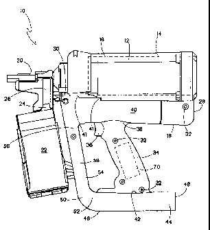
extended periods of use. Tool weight is especially important when work is
performed
at chest height or overhead, such as in the installation of walls, ceilings or
overhead
utilities.
[3] Combustion-powered tools are known in the art, and one type of such tools,
also
known as IMPULSE brand tools for use in driving fasteners into Workpieces, is
described in commonly assigned patents to Nikolich U.S. Pat. Re. No. 32,452,
and
U.S. Pat. Nos. 4,522,162; 4,483,473; 4,483,474; 4,403,722; 5,197,646;
5,263.439 and
6,145,724, all of which may be referred to for further details. Similar
combustion-
powered nail and staple driving tools are available commercially from YT W-
Paslode of
Vernon Hills, Illinois under the ]MPULSE , BUILDEX and PASLODE brands.
[4] Such tools incorporate a generally pistol-shaped tool housing enclosing a
small
internal combustion engine. The engine is powered by a canister of pressurized
fuel
gas, also called a fuel cell. A battery-powered electronic power distribution
unit
produces a spark for ignition, and a fan located in a combustion chamber
provides for
both an efficient combustion within the chamber, while facilitating processes
ancillary
to the combustion operation of the device. The engine includes a reciprocating
piston
with an elongated, rigid driver blade disposed within a single cylinder body.
[5] Upon the pulling of a trigger switch, which causes the spark to ignite a
charge of
gas in the combustion chamber of the engine, the combined piston and driver
blade is
forced downward to impact a positioned fastener and drive it into the
workpiece. The
piston then returns to its original, or pre-firing position, through
differential gas
pressures within the cylinder. Fasteners are fed magazine-style into the
nosepiece,
where they are held in a properly positioned orientation for receiving the
impact of the
driver blade.
[6] Conventional combustion fastener driving tools employ straight magazines
holding
approximately 75 fasteners each. In some operational applications,
particularly
commercial construction projects, there is a need for a tool which is capable
of driving
CA 02578771 2007-03-01
WO 2006/025008 2 PCT/IB2005/052809
a greater number of fasteners in a shorter period of time. The use of coil
magazines
with greater fastener capacities is common in electrically or pneumatically
powered
fastener driving tools, but for various reasons, such magazines have not
become
acceptable with combustion tools. Reasons for the undesirability of such high
capacity
magazines in these tools include the additional weight of the fasteners
causing
premature operator fatigue, and the additional energy required to operate the
coil
magazine fastener advance has not proved reliable.
[7] Aside from the size of the magazine of conventional combustion tools, the
weight,
balance and overall ergonomics of conventional tools have not been suitable
for high
volume commercial construction applications, among others. Often, when such
tools
are used for high firing rate installations, approaching or exceeding 100
fasteners per
minute, tool ergonomics becomes important in maintaining operator satisfaction
with
the tool. In such applications, the operator holds the tool for driving
fasteners into a
vertical surface such as wallboard. As such, the longitudinal axis of the
combustion
engine is generally horizontal or generally parallel to the ground. Since the
combustion
engine is usually the heaviest component of the tool, it has a tendency to
exert a
counterforce to the operator's efforts to control the position of the tool
against the
workpiece. As a result, the tool tends to be top-heavy, which results in
operator fatigue
after extended use.
[8] In some applications, operators find that opportunities arise for holding
the tool
with both hands. Such applications include, but are not limited to situations
where the
tool is held chest-high or overhead for extended periods of time. While
auxiliary
handles are well known for many types of power tools, they typically are
provided in
the form of stub-shafts which are fastened to the tool housing to project
outwardly. In
the case of combustion-powered fastener-driving tools, design factors of
weight and
balance are more critical, and conventional auxiliary handles have not been
widely
adopted.
[9] Also, since balance of combustion-powered fastener-driving tools is
important for
operator satisfaction, and since the combustion engine is relatively heavy,
designers
have used the handle to locate other tool components such as electronic
control
modules, batteries and the like. Such placement offsets the imbalance caused
by the
combustion engine. However, tool imbalance remains an operational factor for
the use
of combustion-powered tools in commercial applications.
[10] Another design factor related to combustion-powered fastener-driving
tools is that
tool and/or environmental temperature influences tool performance, including
but not
limited to the return of the piston to the prefiring position at the end of
the firing/
fastener-driving operational cycle. Piston return is accomplished through
differential
gas pressure within the tool's engine, and such gas pressures are influenced
by ambient
CA 02578771 2009-04-09
WO 2006/025008 3 PCT/1B2005/052809
temperatu e, particularly in exceptionally hot or cold conditions.
[11] An operational factor in the use of combustion powered tools is that
ambient
temperature influences tool performance. At lower ambient temperatures, more
fuel is
needed to obtain desired combustion. However, conventional tools are incapable
of
adjustment to variations in ambient conditions.
[121 Still another design factor of such tools is the tendency of conventional
combustion
tools used in commercial construction applications to jam due to close toll
antes
between the magazine, the nosepiece and the fasteners being fed from the
magazine to
the nosepiece. Frequent jams increase operator frustration with such tools.
[13] Thus, there is a need for a power tool having,a supplemental handle which
does not
impair the balance, or add significant weight to the tool. There is also a
need for a sup-
plemental handle for a combustion-powered tool *Inch is suitable for
incorporating
tool components, including but not limited to electronics, batteries and/or
temperature
monitoring devices.
BRIEF SUMMARY
[141 The above-listed needs are met or exceeded by the present handle for a
power tool.
The handle includes a main portion or primary handle configured for
accommodating
the primary hand used to operate the trigger. A secondary or supplemental
handle
portion is configured to specifically accommodate the non-dominant hand and
provides
a connection point between a battery housing and a magazine. In a preferred
embodiment, the secondary handle is independent of the battery housing and the
magazine of the tool.
[151 More specifically, a housing for a power tool includes a primary handle
configured
for accommodating a primary hand used to control the operation of the tool,
the handle
having a first end closer to a power source of the tool, and a second end
distal of the
power source, a secondary handle configured for accommodating a secondary
hand,
being associated with the distal end and defining a distal extremity of the
tool
offsetting the power source.
CA 02578771 2009-04-09
3A
[15A] The invention in one broad aspect pertains to a housing for a power tool
having a nosepiece end and a combustion end, the housing comprising:
a primary handle configured for accommodating a primary hand used to control
the operation of the tool, the primary handle having a first end closer to a
power
source of the tool, and a second end distal of the power source. A secondary
handle configured for accommodating a secondary hand, being associated with
the distal end and defining a distal extremity of the tool offsetting the
power
source; wherein the primary handle is closer to the nosepiece end than to the
combustion end for improving balance of the tool. There is a magazine, the
secondary handle providing a mounting point for the magazine, and a support
strut extends from the magazine mounting point toward the power source.
BRIEF DESCRIPTION OF THE SEVERAL VIEWS OF THE DRAWINGS
[16] FIG. 1 is a side elevation of a combustion-powered fastener-driving tool
incorporating the present handle housing;
[17] FIG. 2 is a side elevation of a combustion-powered fastener-driving tool
incorporating the present handle housing, with portions shown cut away for
clarity;
[18] FIG. 3 is a perspective view of a battery tray configured for use with
the
present handle housing; and
[19] FIG. 4 is a fragmentary side elevation of an alternate embodiment of the
present handle housing.
CA 02578771 2009-04-09
WO 2006102500$ 4 PCTFIB200s/OS2809
w i.
DETAILED DESCRIPTION
[20] Referring now to FIG. 1, a combustion -powered, fastener-driving tool
suitable for
incorporating the present handle housing is generally designated 10. While the
tool 10
is depicted as being of the type described in the patents listed above, other
types of
fastener-driving tools are contemplated as having the potential of
incorporation of the
present handle housing. The tool 10 includes a main housing 12, usually
injection
molded plastic. In the present tool 10, a variation of the housing
construction is that a
power source 14 (preferably a combustion-powered power source as is known in
the
art and shown hidden) is enclosed by a power source housing 16, and a separate
handle
housing generally designated 18 is joined to the power source housing and to
the tool.
(21] Other major components of the tool are the nosepiece assembly 20, which
contacts
the were and through which fasteners (not shown) are driven, and a magazine 22
providing a supply of fasteners (not shown) and configured for feeding the
fasteners to
the nosepiece assembly. In the preferred embodiment, the magazine is a coil-
type,
retaining a relatively large number of fasters (at least 150) and the magazine
ad-
vancement is powered by exhaust gases generated in the combustion process as
described in U.S. Patent No. 5,558,264, which may be referred to for further
details. However, the present tool 10 is also contemplated as being used with
straight, spring-advanced magazines having a reduced fastener capacity. The
coil magazine 22 is configured for engagement with the nosepiece assembly 20
so that fasteners may be fed easily and with limited opportunity for becoming
jammed in the delivery process. As such, a forward end 24 of the magazine 22
is slidingly engaged upon a receiving portion 26 the nosepiece assembly 20.
[22] Referring now to FIGs.1 and 2, the handle housing 18 is shown being
secured
along the power source housing 16 from a combustion end 28 to a nosepiece and
30.
As is well known in the art, the handle housing 18 is provided in two halves
joined
along a vertical parting line and secured together with fasteners at several
fastener
points 32. PIG. 2 depicts the handle housing 18 with one such half removed.
Included
on the handle housing 18 is a primary handle 34 configured for accommodating a
primary hand used to control the operation of the tool The primary handle 34
in-
corporates a trigger switch 36 configured for initiating combustion and other
tool
functions as is well known in the art. A first end 38 of the primary handle
34, is closer
to the power source 14, and is joined to a fuel cell chamber 40 which is
directly
connected to the tool 10 adjacent the power source housing 16. Depending on
the ap-
plication, the handle housing 18 may be directly fastened to the power source
housing
16, or maybe fastened to the tool 10 to tightly engage the power source
housing. To
facilitate this engagement with the power source housing 16, the fat cell
chamber 40
is preferably provided with conforming formations 41 (FIG. 1) which follow the
outer
CA 02578771 2007-03-01
WO 2006/025008 5 PCT/IB2005/052809
contour of the power source housing at the point of contact. In the preferred
embodiment, to improve tool balance, the primary handle 34 is located closer
to the
nosepiece end 30 than to the combustion end 28. This is a departure from
conventional
tools, in which the handle is equidistant from the two ends. It has been found
that tool
balance is significantly improved by moving the primary handle 34 closer to
the
nosepiece end 30, especially when the tool 10 is used for installation of
walls, in which
position the power source longitudinal axis is generally parallel to the
ground, or in a
generally horizontal position.
[23] A second end 42 of the primary handle 34 is distal of the power source 14
relative
to the first end 38. As is known in the art, the primary handle 34 is
preferably er-
gonomically shaped for promoting comfort of the user's main tool controlling
hand. In
the preferred embodiment, a battery housing 44 is associated with, and
preferably
joined to the second end 42, and is oriented to be generally parallel to the
longitudinal
axis of the power source 14 and the fuel cell chamber 40. In addition, it will
be seen
that the second end 42 is joined to the battery housing 44 closer to a
nosepiece end 46
of that housing than to a combustion end 48 of that housing. Thus, when
equipped with
a battery 49 (FIG. 2), and with the movement of the primary handle 34 as
described
above, the battery housing 44 contributes to the counterbalancing of the
normally
inherently nosepiece-heavy condition of such tools. Accordingly, the tool 10
is more
equally balanced when held in an operational position.
[24] To enhance operator comfort, the handle housing 18 is provided with a
secondary
handle 50 configured for accommodating a user's secondary hand, being
associated
with the second or distal end 42 and defining a distal extremity of the tool
offsetting
the power source 14. In the preferred embodiment, the secondary handle 50 has
a first
end 52 connected to the nosepiece end 46 of the battery housing 44, and a
second end
54 connected to a support strut 56. It will be seen that the secondary handle
50 is
connected to the tool 10 by the support strut 56 independently of any
connection to the
magazine 22. Also, the secondary handle 50 is located between the battery
housing 44
and the magazine 22, and is a distinct portion of the handle housing 18
relative to the
battery housing 44. As seen in FIGs. 1 and 2, the secondary handle 50 is also
distinct
from the magazine 22.
[25] In addition, the second end 54 preferably provides a mounting point 58
for the
magazine 22. The support strut 56 extends generally from the magazine mounting
point 58 toward the power source 14, and more specifically is joined to the
fuel cell
chamber 40. It is contemplated that the mounting point 58 may be located
elsewhere
on the secondary handle 50 depending on the application. In the preferred
embodiment,
the primary handle 34, the secondary handle 50, the battery housing 44, the
fuel cell
chamber 40 and the support strut 56 are integrally formed in each half of the
handle
CA 02578771 2007-03-01
WO 2006/025008 6 PCT/IB2005/052809
housing 18 by injection molding or similar production process, however it is
con-
templated that the components may be separately formed and joined together
using
fastener technologies such as screws, rivets, adhesives, ultrasonic welding or
the like.
[26] Referring now to FIG. 2, it will be seen that the mounting point 58 is
the primary
mount for the magazine 22 to the tool 10. As described above, the engagement
of the
forward end 24 of the magazine 22 with the nosepiece assembly 20 is a sliding
one to
facilitate fastener feeding and to prevent jamming. Thus, especially with the
coil-type
magazine 22 holding as many as 150 fasteners, the significant weight of this
component requires a stable and positive mounting arrangement with the tool
10. The
secondary handle 50 addresses this requirement with the mounting point 58.
[27] More specifically, the magazine 22 has a wedge-shaped mounting tab 60,
and the
secondary handle 50 defines a wedge-shaped chamber 62 dimensioned for
capturing
the tab. A central aperture 64 on the tab 60 engages a fastener boss 66 in the
chamber
62, and a fastener (not shown) passing through the aperture secures the
respective
housing halves together and the tab 60 in the chamber 62. Once the halves of
the
handle housing 18 join around the tab 60 as shown in FIG. 1, the tab is
closely
supported on at least four sides as well as being secured by the fastener and
is
prevented from significant movement relative to the secondary handle 50.
[28] Another feature of the secondary handle 50 is that it is configured for
receiving a
thermister diagrammatically represented at 68 as a circuit board which is
electrically
connected to a central processing unit or CPU 70 (shown hidden in FIG. 1). As
is well
known in such tools, the CPU 70, preferably located in the primary handle 34,
controls
the operational cycle of the tool, including, among other things, the
injection of the
fuel into the combustion chamber when electronic fuel injection is provided,
the
operation of the fan inside the combustion chamber and ignition of the
combustible
mixture inside the combustion chamber. It is contemplated that the CPU 70 is
pro-
grammable to receive temperature data from the thermister 68 and adjust
operation of
the tool accordingly. An advantage of placing the thermister 68 in the
secondary
handle 50 is that the thermister is located as distally as possible from the
power source
14, and as such provides a usable indicator of ambient temperature which is
outside the
temperature influence generated by the relatively hot power source 14 during
typical
tool operation.
[29] A raceway 72 is formed in the handle housing 18 connecting a chamber 74
in the
secondary handle 50 for retaining the thermister 68 and a chamber 76 in the
primary
handle 34 retaining the CPU 70 to provide a place for the wiring from the
thermister to
the CPU. The raceway 72, as well as the chamber 76, are configured to
accommodate
CPUs designed for either electronic or mechanical fuel injection. Also, the
placement
of the magazine mount 58 between the thermister 68 and the power source 14 and
CA 02578771 2007-03-01
WO 2006/025008 7 PCT/IB2005/052809
relatively closer to the power source affords additional thermal insulation of
the
thermister from the power source.
[30] Referring now to FIGs. 2 and 3, it has been found that manufacturing of
the handle
housing 18 is facilitated if the battery housing 44 includes a separate
battery tray 78
insertable in the battery housing and provided with at least one contact 80.
The battery
tray 78 contacts 80 are metallic and are constructed and arranged to engage
similar
contact terminals (not shown) on the battery 49 (FIG. 2). A main body 82 of
the battery
tray 78 is configured for receiving the battery 49, and the tray is positioned
inside the
housing 44 once the two halves of the handle housing 18 are joined. In this
manner,
separate fasteners are not needed for retaining the battery tray in place.
[31] Referring now to FIG. 4, an alternate embodiment of the handle housing 18
is
generally designated 88. Shared components of the two housings have been
designated
with identical reference numbers. A main distinction between the handle
housings 18
and 88 is that in the latter, instead of the integrally formed secondary
handle 50 with its
support strut 56, a separate secondary handle bracket 90 is provided, having a
handle
end 92 and an opposite magazine end 94. The bracket 90 is made of a stiff
material
such as metal or durable plastic, and is fastened to the second or distal end
42 of the
primary handle 34 through a corresponding eyelet 96. Upon assembly, the handle
end
92 of the bracket 90 is captured between the joined halves of the handle
housing 88.
[32] At the magazine end 94, a magazine eyelet 98 is used to fasten the
bracket 90 to the
magazine mounting tab 60. Thus, the bracket 90 directly connects the primary
handle
34 to the magazine 22. As is well known in the art, the fasteners used in
attaching the
bracket 90 to the tool 10 are preferably threaded fasteners however other
types known
in the art are contemplated. The bracket 90 forms the secondary handle, and as
such
provides a place for the user to place the subordinate hand not controlling
the tool
operation through the trigger switch 36. In the housing 88, it will also be
seen that a
battery housing 100 is connected to the distal end 42 as is the housing 44,
but has both
of the nosepiece end 46 and the combustion end 48 free of any connection to
other
components. As is the case with the handle end 92, the battery housing 100 is
captured
upon assembly at a battery housing eyelet 102 between the halves of the handle
housing 88. The battery tray 78 is positioned within the battery housing 100
and is
preferably provided with at least one and preferably four standoffs or legs
104 (shown
hidden) for achieving proper positioning.
[33] Thus, the handle housings 18, 88 provide improved tool balance, as well
as secure
mounting arrangements for high capacity coil-type magazines. The primary
handle 34,
as well as the battery housings 44, 100 are positioned for improved balance,
especially
when the tool is used for constructing walls. In addition, structure is
provided for
storing and connecting a thermister for measuring ambient temperatures.
CA 02578771 2007-03-01
WO 2006/025008 8 PCT/IB2005/052809
[34] While a particular embodiment of the present primary and secondary
handles for a
power tool have been described herein, it will be appreciated by those skilled
in the art
that changes and modifications may be made thereto without departing from the
invention in its broader aspects and as set forth in the following claims.