Note: Descriptions are shown in the official language in which they were submitted.
CA 02578786 2007-03-01
WO 2006/028971 PCT/US2005/031333
TRANSL~ATABLE CARRIAGE FIXATION SYSTEM
CROSS-REFERENCE TO RELATED APPLICATION
[0001] This application is a continuation-in-part of U.S. Patent Application
Serial
No. 10/932,392, filed September 2, 2004, which is a continuation-in-part of
U.S. Patent
Application Serial No. 10/653,164, filed September 3, 2003, the entire
disclosure of each
application is expressly incorporated by reference herein.
FIELD OF THE INVENTION
[0002] The present invention is related to a fixation system. More
particularly, the
invention is related to a fixation system consisting of a translational plate
system with a
plurality of fixation holes.
BACKGROUND OF THE INVENTION
[0003] Orthopedic fixation devices such as plates are frequently coupled to
bone
with fasteners inserted through plate holes. It is known that securing such
fasteners to the
bone plate, for example through the use of expansion-head screws, can decrease
the
incidence of loosening of the fixation assembly post-operatively. It is also
known that a
bushing may be disposed in each plate hole to receive the fastener to permit
polyaxial
movement so that the fastener may be angulated at a surgeon-selected angle.
However,
polyaxial movement of fasteners through set plate hole locations only
increases attachment
alternatives of the fasteners themselves. The plate holes remain fixed in
relation to each
other and to the longitudinal axis of the plate.
[0004] Typically, a spinal fixation plate is applied to the anterior side of
the affected
vertebrae to span at least one affected disc space or vertebra (i.e. one in
which at least a
portion of the disc has been removed and a spinal fusion spacer has been
inserted). The
plate is fixed to the vertebrae using bone screws and acts to keep the
vertebrae generally
aligned during the initial period following fixation in which fusion of the
spacer to the
adjacent vertebrae occurs. The plate also may act to prevent the spacer from
being
expelled from the disc space during this initial period.
[0005] Where a spinal fusion spacer is implanted between a pair of vertebrae
to be
fused, the spacer rests on the endplates of the vertebrae. The outer
circumference of the
end plates comprises hard cortical bone and thus provides the best sur face
upon which to
seat the spacer. The center portion of the endplates comprises a thin cortical
bone shell
overlying a core of softer cancellous bone. Most, if not all, of the spacer
contact surface,
however, may be located in this center portion. ,
[0006] Subsequent to placement of the spacer, the surgeon typically compresses
the disc space by pressing the adjacent vertebrae together. This compression
ensures a
-1-
NYJD: 1590358.1
CA 02578786 2007-03-01
WO 2006/028971 PCT/US2005/031333
b~~rger~,;t~Võ~pacer and the endplates, increasing the chances that
fusion will occur. Often in the period immediately following surgery, the
spacer may
subside slightly into the under-portion of the endplates, or the space between
the vertebral
endplates may decrease due to graft resorption (in the case of allograft
spacers).
[0007] Where a rigid fixation plate is used to connect the vertebrae, this
subsidence
may tend to shift more of the spinal load to the plate than is desirable. Such
load shifting
can also occur due to inaccuracies in installing the plate to the vertebrae.
In extreme
circumstances, this load shifting can result in non-fusion of the spacer to
the vertebra,
since firm compression between the spacer and the vertebrae is one factor
contributing to
successful fusion.
[0008] Accordingly, there exists a need for a fixation system which provides
the
desired support to the vertebrae to be fused, and which allows limited
translation of the
vertebrae with respect to at least a portion of the plate, thereby limiting
the undesirable
effects of load shielding by the plate due to graft subsidence caused by
settling or normal
forces experienced in the spinal column. Promoting fusion of the adjacent
vertebrae may
thus accomplished.
[0009] Translation plates which compensate for this subsidence by providing
the
aforementioned benefits of a rigid fixation plate (general vertebral
alignment, and
prevention of spacer expulsion), while allowing at least one vertebra to move
with respect
to the plate to compensate for post-surgical subsidence, may be desirable.
This
compensation may permit the majority of the spinal column load to be borne by
the spacer
rather than the plate.
SUMMARY OF THE INVENTION
[0010] An embodiment of a bone fixation assembly is described, comprising: a
first
plate having a first end, a second end, a longitudinal axis, and upper
surface, and a lower
surface, the first plate having at least two fixation holes extending from the
upper surface to
the lower surface, the first plate further comprising first and second
extending segments
extending near the first end of the first plate in the direction of the
longitudinal axis, the first
extending segment associated with the upper surface and the second extending
segment
associated with the lower surface, and a first cavity formed between the
extending
segments; and at least one carriage block having at least two fixation holes;
wherein the at
least one carriage block is received and retained within the first cavity and
is slidably
moveable with respect to the first plate.
[0011] The first plate may further comprise a second cavity. The assembly may
further comprise a second carriage block slidably associated with the first
plate within the
second cavity. The second carriage block may be slidable independent of the
first carriage
block. The second carriage block may comprise at least two fixation holes.
-2-
NYJD: 1590358.1
CA 02578786 2007-03-01
WO 2006/028971 PCT/US2005/031333
!) [(~1Z~]. " il,,.l- :!: i~ lf,'~I~e d carriage blocks may be permitted to
slide
simultaneously. The first carriage block may be permitted to slide over a
greater distance
than that of the second carriage block. The sliding distance of the second
carriage block
may be limited by a motion-limiting element. The first carriage block may be
permitted to
slide from about 0 mm to about 10 mm relative to the first plate.
[0013] The first plate may further comprise at least one recess. The assembly
may
further comprise a securing element insertable in a recess. The securing
element may be
able to limit the translatable movement of the first carriage block along the
longitudinal axis.
At least one recess may extend from the upper surface to the lower surface. At
least one
recess may be substantially circular, substantially oblong, and/or
substantially polygonal.
At least one recess may be able to receive a drill guide, and/or a temporary
attachment
element.
[0014] The first plate may have four fixation holes, and wherein the fixation
holes
are arranged in pairs. The first plate further may comprise at least one
indent able to
facilitate the bending of the first plate. At least two fixation holes may be
substantially
circular, and may further comprise a clip. At least two fixation holes may be
substantially
oblong. At least two fixation holes may each have a longitudinal axis, and
wherein the at
least two fixation holes allow for the translation of a fastener along the
longitudinal axis of
each of the at least two fixation holes. At least two fixation holes may allow
for selective
placement of a fastener within each of the at least two fixation holes.
[0015] The first plate further may comprise at least one internal fixation
element
slidably associated with the first plate. At least one internal fixation
element may further
comprises at least one fixation hole. At least one internal fixation element
may be slidably
translatable in relation to the fixation holes of the first plate. At least
one internal fixation
element may also be slidably translatable in relation to the fixation holes of
the first carriage
block. The first plate may further comprise a groove, and wherein at least one
internal
fixation element is able to situated in the groove.
[0016] The first carriage block may experience a frictional force of at least
50
grams when slidably moving in relation to the first plate.
[0017] The first and second extending segments may each have a longitudinal
axis, and wherein the longitudinal axes of the first and second extending
segments are
divergent. The first and second extending segments may also each have a
longitudinal
axis, and wherein the longitudinal axes of the first and second extending
segments are
convergent. Further, the first and second extending segments may each have a
longitudinal axis, and wherein the longitudinal axes of the first and second
extending
segments are substantially parallel.
[0018] The first plate may comprise a length, and wherein the length of the
first
plate is from about 10 mm to about 140 mm. The first carriage block may
comprise a
-3-
NYJD: 1590358.1
CA 02578786 2007-03-01
WO 2006/028971 PCT/US2005/031333
j;,I.eV,gtO;,,a01 Wh,,~rO[h; 1".0; ~pf,~the first carriage block is from about
5 mm to about 20
mm.
[0019] Another embodiment of a translational bone fixation assembly is
described,
comprising: a first plate having a plurality of fixation holes and a
longitudinal axis; and at
least a first carriage block having a plurality of fixation holes, at least a
portion of the first
carriage block slidably associated with at least a portion of the first plate;
wherein the first
carriage block is translatable in the direction of the longitudinal axis when
the assembly is
attached to at least one bone segment.
[0020] The assembly may further comprise a second carriage block slidably
associated with at least a portion of the first plate. The second carriage
block may be
slidable independent of the first carriage block. The second carriage block
may comprise a
plurality of fixation holes.
[0021] The first and second carriage blocks may be permitted to slide
simultaneously. The first carriage block may have a range of motion greater
than that of
the second carriage block. The range of motion of the second carriage block
may be
limited by a motion-limiting element. The first carriage block may be
permitted to slide from
about 0 mm to about 4 mm relative to the first plate.
[0022] The first plate further may comprise a bore, and wherein an extension
element extends through the bore. The extension element may be able to stop
the sliding
movement of the first carriage block. The extension element may be permanently
attached
to the first plate.
[0023] Another embodiment of a translational bone fixation assembly is
described,
comprising: a first plate having a plurality of fixation holes and a
longitudinal axis; and at
least a first carriage block having a plurality of fixation holes, at least a
portion of the first
carriage block slidably associated with at least a portion of the first plate;
wherein the first
carriage block is translatable in the direction of the longitudinal axis under
a coaxial force of
at least about 50 grams.
[0024] The assembly may further comprise a second carriage block slidably
associated with at least a portion of the first plate. The second carriage
block may be
slidable independent of the first carriage block. The second carriage block
may comprise a
plurality of fixation holes.
[0025] The first and second carriage blocks may be permitted to slide
simultaneously. The first carriage block may have a range of motion greater
than that of
the second carriage block. The range of motion of the second carriage block
may be
limited by a motion-limiting element. The first carriage block may be
permitted to slide from
about 0 mm to about 10 mm relative to the first plate.
[0026] A method of securing at least two bone elements is described,
comprising
the steps of: (a) providing a translatable bone fixation assembly having a
first plate having
-4-
NYJD: 1590358.1
CA 02578786 2007-03-01
WO 2006/028971 PCT/US2005/031333
1ra pIpta14tylj,q!]!:j*.qtiqn;ha(e~ lpngitudinal axis, and a first carriage
block having a
plurality of fixation holes, wherein the carriage block is slidably associated
with the first
plate; (b) inserting at least one fastener through at least one fixation hole
in the first plate
and into a first bone element; (c) inserting at least one fastener through at
least one fixation
hole in the first carriage block and into a second bone element; and (d)
permitting the
carriage block to slide in the direction of the longitudinal axis after
implantation of the bone
fixation assembly.
[0027] The assembly may further comprise a second carriage block slidably
associated with the first plate, and wherein the second carriage block has a
plurality of
fixation holes. The method may further comprise the step, inserted before step
(d), of
inserting at least one fastener through at least one fixation hole in the
second carriage
block and into a third bone element.
[0028] The third and second bone elements may be separated by the first bone
element.
[0029] The method may further comprise the step of inserting applying a motion-
limiting element to limit the motion of the first carriage block. The method
may further
comprise the step, inserted before step (b), of drilling at least one hole in
at least one bone
element in a location of desired fastener insertion.
[0030] The first and second bone elements may be adjacent vertebrae.
[0031] The method may further comprise the step of inserting an intervertebral
spacer between the first and second bone elements.
[0032] A kit for use with bone fixation procedures is also described,
comprising: at
least a first plate having a plurality of fixation holes and a longitudinal
axis; at least a first
carriage block having a plurality of fixation holes, at least a portion of the
first carriage block
slidably associated with at least a portion of a first plate; wherein the
first carriage block is
translatable in the direction of the longitudinal axis when the assembly is
attached to at
least one bone segment.
[0033] The kit may further comprise at a first fastener for use with at least
one
fixation hole. The kit may further comprise a second fastener for use with at
least one
fixation hole, wherein the first fastener is substantially different than the
second fastener.
[0034] The kit may further comprise a second plate and a second carriage
block.
The first carriage block may be slidably associated with the second plate. The
second
carriage block may be slidably associated with the first plate. The first and
second carriage
blocks may be able to be simultaneously slidably associated with the first
plate.
[0035] The kit may further comprise at least one motion-limiting element for
use
with a carriage block. The kit may further comprise at least one temporary
attachment
element. The kit may further comprising at least one drill guide, and/or at
least one drill.
-5-
NYJD: 1590358.1
CA 02578786 2007-03-01
WO 2006/028971 PCT/US2005/031333
,~If the first plate slidingly engaged with the first carriage
block is a dovetail portion, wherein at least a portion of the dovetail may be
deformed to
limit the translational motion of the first carriage block.
BRIEF DESCRIPTION OF THE DRAWINGS
[0037] While preferred features of the present invention may be disclosed in
the
accompanying illustrative, exemplary drawings, for the purposes of
description, the
invention as defined by the claims should be in no way limited to such
preferred features or
illustrative and exemplary drawings, wherein:
[0038] Fig. 1a is a perspective view of an embodiment of a translational
spinal
plate in a fully compressed configuration;
[0039] Fig. 1b is a perspective view of the plate of Fig.1a in a fully
extended
configuration;
[0040] Fig. 1c is a cross-sectional view of the plate of Fig. 1b, taken along
line A-
A;
[0041] Fig. 1 d is an enlarged partial cross-sectional view of the plate of
Fig.1 b
taken along the line A-A;
[0042] Fig. 1e is a partial elevation view of the plate of Fig.1b, taken along
line B-
B;
[0043] Fig. 1f is a top view of an embodiment of the carriage block of Fig.
1a;
[0044] Fig. lg is a front view of the carriage block of Fig. 1f;
[0045] Fig. 2a is a side view of an exemplary bone fastener for use with the
plate of
Fig. 1 a;
[0046] Fig. 2b is a top view of an exemplary retention clip for use with the
plate of
Fig. 1 a;
[0047] Fig. 3a is a perspective view of an embodiment of a translating spinal
plate
for use in a two-level spinal fusion procedure, the plate being shown in the
fully extended
position;
[0048] Fig. 3b is a perspective view of the plate of Fig. 3a, in the fully
compressed
condition;
[0049] Fig. 3c is a partial top view of the plate of Fig. 3a;
[0050] Fig. 3d is a partial top view of a hexagon-shaped recess for use with a
plate;
[0051] Fig. 3e is an partial top view of a square-shaped recess for use with a
plate;
[0052] Fig. 3f is a top view of an embodiment of a translational spinal plate
with an
overlapping hexagonal recess;
-6-
NYJD: 1590358.1
CA 02578786 2007-03-01
WO 2006/028971 PCT/US2005/031333
ii Cqi~S~~.; "-I,,.I~' ::i~ Il lr*ilg~.,4a:;~~;:i~:~op:iiiiew of another
embodiment of a translational spinal plate
with a pair of slotted bone screw holes;
[0054] Fig. 4b is a top view of the slotted bone screw hole of Fig. 4a;
[0055] Fig. 5a is a perspective view of another embodiment of a translational
spinal
plate with an internal carriage block;
[0056] Fig. 5b is a cross-sectional view of the plate of Fig. 5a taken along
the line
F-F;
[0057] Fig. 5c is a perspective view of a two-piece internal carriage block
that may
be used with the plate of Fig. 5a;
[0058] Fig. 6 is perspective view of another embodiment of a translational
spinal
plate with a plurality of internal carriage blocks;
[0059] Fig. 7a is a top view of another embodiment of a translational spinal
plate
with both a pair of slotted bone screw holes and an internal carriage block;
[0060] Fig. 7b is perspective view of another embodiment of a four-level
translational spinal plate with two pairs of slotted holes;
[0061] Fig. 7c is a top view of the plate of Fig. 7b;
[0062] Fig. 8a is an exploded view of another embodiment of a translational
spinal
plate with a two-piece track-plate construction;
[0063] Fig. 8b is a top view of the plate of Fig. 8a in an assembled
condition;
[0064] Fig. 8c is a front view of an embodiment of a symmetrical carriage
block;
[0065] Fig. 8d is a top view of the carriage block of Fig. 8c;
[0066] Fig. 8e is a front view of an embodiment of an offset carriage block;
[0067] Fig. 8f is a top view of the carriage block of Fig. 8e;
[0068] Fig. 8g is a top view of an alternative carriage block design for use
with the
track-plate of Fig. 8a;
[0069] Fig. 9 is a top view of a motion-limiting shim;
[0070] Fig. 10 is a top view of another embodiment of a translational spinal
plate,
this embodiment having a cam-compression feature;
[0071] Fig. 11 is a perspective view of a corpectomy model of a translational
spinal
plate;
[0072] Fig. 12a is a top view of a further embodiment of an extensible
translational
spinal plate in a compressed position;
[0073] Fig. 12b is a top view of the plate of Fig. 12a in an extended
position;
[0074] Fig. 13a is a perspective view of another embodiment of a translational
spinal plate having a dovetail design;
[0075] Fig. 13b is a cross-sectional view of the plate of Fig. 13a taken along
the
line G-G;
-7-
NYJD: 1590358.1
CA 02578786 2007-03-01
WO 2006/028971 PCT/US2005/031333
view of yet another embodiment of a translational
spinal plate having a dovetail design in a compressed condition;
[0077] Fig. 14b is a perspective view of the plate of Fig. 14a in an expanded
condition;
[0078] Fig. 15 is a perspective view of the base plate of Figs. 14a-14b, with
a
carriage block removed for clarity;
[0079] Fig. 16 is a perspective view of a carriage block for use with the
plate of Fig.
15;
[0080] Fig. 17a is a perspective view of still another embodiment of a
translational
spinal plate having a dovetail design in a expanded condition; and
[0081] Fig. 17b is a perspective view of the plate of Fig. 17a in a partially
compressed condition.
DETAILED DESCRIPTION OF THE PREFERRED EMBODIMENTS
[0082] The plates described herein may be used in spinal fusion procedures in
which a damaged or diseased disc (or part of a disc) is removed from between a
pair of
vertebrae and a spinal fusion spacer is placed between the vertebrae. The
plates may be
applied to an anterior portion of the affected vertebrae to span the affected
disc space, and
may be fixed to the vertebrae using bone screws. The plate may function to
maintain the
vertebrae aligned during the initial period following fixation in which fusion
of the spacer to
the adjacent vertebrae occurs. The plate may also function to share some of
the axial
spinal load applied to the fusion spacer to prevent extreme subsidence of the
spacer into
the vertebral body, such as where the patient has poor bone quality. The
plates may also
act to prevent the spacer from being expelled from the disc space during the
initial post-
operative period.
[0083] The plates may be used for single level (i.e. one-disc) or multiple-
level (i.e.
multiple disc) fusion procedures. Some embodiments may be used for corpectomy
procedures, in which at least a portion of a vertebral body is removed. Single
level plates
generally may have two pairs of bone screw holes, while the multi-level plates
generally
may have three or more pairs of holes. While the plates herein are described
with
reference and application to the spine, it will be appreciated that features
of the plates and
the plates may have other applications, and can be applied to other bones
and/or parts of
the skeleton.
[0084] Fig. 1 a shows a translating spinal fixation plate 1 for use in a
single-level
fusion procedure in which first plate segment 2 and carriage block 4 are
configured to be
fixed to first and second vertebra so that the plate 1 spans the disc space
between the
vertebrae. The plate 1 may have a longitudinal axis A-A and the first plate
segment 2 and
carriage block 4 may each have one or more bone fastener hole(s) 6, 8 for
receiving a
-8-
NYJD: 1590358.1
CA 02578786 2007-03-01
WO 2006/028971 PCT/US2005/031333
li::bdt1~l'fas11~H'e~'rl(~d:a4=fiii~;;tFal~ tive plate segment and carriage
block to the associated
vertebral body. The first plate segment 2 may have upper and lower surfaces
10, 12, while
carriage block 4 may have upper and lower surfaces 14, 16. The lower surfaces
12, 16
may be configured to engage a portion of a respective vertebral body. In the
illustrated
embodiment, the first plate segment 2 and carriage block 4 are configured to
be fixed to the
anterior surfaces of a pair of adjacent vertebra. Fig.1f shows a top view of
the carriage
block 4 in more detail, and Fig. 1 g shows a front view of the same.
[0085] As illustrated in Figs.lb-1e, the first plate segment 2 may have
respective
translating surfaces 18a, 18b, while the carriage block 4 may have respective
translating
surfaces 20a, 20b configured to allow the segment and carriage block to slide
toward (or
away from) each another along the longitudinal axis A-A of the plate 1. The
plate 1 may
have an initial length "PLE" sufficient to span the disc space and to allow
fixation of a plate
segment 2 and carriage block 4 to each vertebra.
[0086] The translating surfaces are illustrated in more detail in Figs. 1c-1e,
in
which the respective translating surfaces are configured and dimensioned to
cooperate to
allow the first plate segment 2 and carriage block 4 to slide with respect to
each other,
while maintaining the desired structural integrity of the plate 1 in bending
and torsion.
Thus, when the first plate segment 2 and carriage block 4 are fixed to
respective adjacent
vertebrae using bone fasteners, subsequent movement of the vertebrae along the
axis of
the spine (e.g. due to subsidence of the intervertebral spacer into the end
plates of the
associated vertebral bodies) may cause the first plate segment 2 and carriage
block 4 to
slide together along the longitudinal axis A-A, reducing the length PLc" of
the plate 1.
Preferably the plate segment 2 and the carriage block 4 will move in an amount
equal to
the amount of subsidence of the spacer into the adjacent vertebrae.
[0087] The translation of the carriage block 4 with respect to the first plate
segment
2 is contemplated and preferably provided by spinal fixation plate 1 after it
has been
implanted into the body. Such translation may be urged by, for example, forces
within the
spinal column that may directly bear upon fasteners inserted into fastener
holes 6, 8 of first
plate segment 2 and carriage block 4. When a translating force acts in situ
upon the first
plate segment 2 and/or the carriage block 4, translating surface 20a may
translate relative
to translating surface 18a, or vice versa. Likewise, translating surface 18b
may translate
relative to translating surface 20b, or vice versa. As described in more
detail below, the
respective pairs of translating surfaces 18a, 20a and 18b, 20b may or may not
contact
each other during the translation of the carriage block 4 relative to the
first plate segment 2.
Moreover, any of all of translating surfaces 18a, 18b, 20a, 20b may be angled,
or for
example, roughened, to produce a desired contact and/or resistance to
translation between
the respective pairs of translating surfaces 18a, 20a and 18b, 20b. Such
variations are
also described in more detail below.
-9-
NY1D: 1590358.1
CA 02578786 2007-03-01
WO 2006/028971 PCT/US2005/031333
.gMent 2 and carriage block 4 may also have respective
compression stop surfaces 22a, 22b; 24a, 24b that may engage each other when
the plate
is in the fully compressed condition (see Fig.1 a). The first plate segment 2
and carriage
block 4 may further have respective extension stop surfaces, 27a, 28 (see Fig.
1 e) that
may engage each other when the plate is in the fully extended condition (see
Fig. 1 b). The
first extension stop surface 27a may take the form of an extension member 27,
such as, for
example, a rivet, pin, screw or other suitable extension disposed in a bore 30
in the first
plate segment 2. The second extension stop surface 28 may comprise an end
surface of
the second plate segment 4. The second extension stop surface 28 may at least
partially
conform to the shape of the first extension stop surface 27a. The extension
member 27
may be removably attached to the first plate segment 2 to allow substitution
of different-
sized or different styled carriage blocks 4 may be permanently fixed to the
first plate
assembly to capture the carriage block 4 and prevent disassembly. When the
plate 1 is
assembled, the first plate segment 2 and carriage block 4 may slide between
the fully
extended and fully compressed conditions, the amount of compression (or
extension) of
the plate may be limited by the arrangement of the stop surfaces. It will be
recognized that
the plate 1, and particularly the first plate segment 2 and the carriage block
4 may employ
other stop surfaces to limit the amount of travel of the carriage block 4 with
response to the
first plate segment 2.
[0089] The plate segments and carriage blocks may each have a first width
"PW1"
corresponding to the dimension transverse to the longitudinal axis as measured
across the
portion of the plate having the bone fastener holes 6a, 6b, 8a, 8b. The first
plate segment
2 and carriage block 4 further may have a second width "PW2" as measured
across the
portion of the respective segment that does not contain the bone fastener
holes. The first
width PW1 may be about 10 mm to about 60 mm, while the second width PW2 may be
about 6 mm to about 56 mm. The first plate segment 2 and carriage block 4 may
have
specialized widths for spinal applications. For example, for assemblies used
in the cervical
region, PW1 may be from about 10 mm to about 20 mm and PW2 may be from about 6
mm to about 20 mm. Also, for assemblies used in the thorcolumbar region, PW1
may be
from about 16 mm to about 30 mm and PW2 may be from about 10 mm to about 30
mm.
Further, for assemblies.used in the lumbar region, PW1 may be from about 20 mm
to about
60 mm and PW2 may be from about 16 mm to about 60 mm. The first plate segment
2
and carriage block 4 may each have a thickness "PT" which may be about 1 mm to
about
mm, and more preferably from about 2 mm to about 4 mm.
[0090] In the fully compressed condition, the plate length PL may be from
about 10
mm to about 138 mm, and in the fully extended condition the plate length PL
may be from
about 12 mm to about 140 mm. The compressed and extended lengths may vary
depending on the size of the patient, the region of the spine in which the
plate is used.
-10-
NYJD: 1590358.1
CA 02578786 2007-03-01
WO 2006/028971 PCT/US2005/031333
I111604 lumbar spine applications in larger patients, while
smaller sizes may be used for cervical spine applications in small patients.
[0091] The plate 1 may be curved to more naturally conform the plate to the
normal
anatomical curvature of the spinal column. Thus, when used in the cervical and
lumbar
spine, the plate may have a lordosed, or convex shape. When used in the
thoracic spine,
the plate may have a kyphosed, or concave shape. Alternatively, the plate may
be
provided in a flat configuration to fit to a lateral portion of the spine. The
first plate segment
2 and carriage block 4, and in particular their lower surface 12, 16, may also
be provided
with a lateral curvature allowing them to closely conform to individual
vertebral elements.
For example, as seen in Figs. 1 c-1 g, carriage block 4 may have a radius Rc
along its lower
surface 16, and the first plate segment 2 may have a radius RP along its lower
surface 12.
Radius Rc may be from about 10 mm to about 60 mm, and radius RP may be from
about 10
mm to about 60 mm. The first plate segment 2 and carriage block 4 may also be
bendable
to allow the surgeon to modify the plate curvature as desired to customize the
plate to the
anatomy of an individual patient.
[0092] The lower surfaces 12, 16 of the first plate segment 2 and carriage
block 4
may be roughened to enhance engagement between the plate and the associated
vertebral body. Such roughening may be achieved by bead blasting the surfaces
12, 16 by
machining ridges, grooves, or other surface profiles or projections into the
surfaces, or by
applying a roughening material to the lower surfaces.
[0093] Figs. 1c-1e illustrate translating surfaces 18, 20 of plate 1
configured to
provide a compression-resisting force that varies with the amount of
translation between
the first plate segment 2 and carriage block 4. As shown, the first plate
segment 2 has
upper and lower extending segments 33a, 33b each having a translating surface
18a, 18b
configured to slidably engage the surfaces 20a, 20b of the carriage block 4.
As shown in
Fig.1e, the translating surfaces 18a, 18b of the first plate segment 2 may
form an angle a
with respect to each other so that as the carriage block 4 moves, the carriage
block 4
wedges against the translating surfaces 18a, 18b of the first plate segment 2
thus providing
a force that increasingly opposes movement of the carriage block 4 as the
carriage block 4
travels toward the vertex of angle a. In the embodiment shown in Fig.1e, angle
a is
slightly divergent. Alternatively, however, angle a may be convergent, such
that surfaces
18a, 18b of the carriage block 4 may encounter more friction as carriage block
4 translates
toward the first and second ends 32a, 32b of the first and second extending
segments 33a,
33b of first plate segment 2. Moreover, angle a may not exist at all if
surfaces 18a, 18b
are substantially parallel. This may be preferable in light of the fitting and
contouring
options discussed below. All of these designs may be useful in preventing
extreme
subsidence of the associated intervertebral spacer. The wedge angle a may be
from about
1 degrees to about 10 degrees, and may generally correspond to variances in
the recess
-11-
NYJD: 1590358.1
CA 02578786 2007-03-01
WO 2006/028971 PCT/US2005/031333
xis of the first plate segment 2. Moreover, the translating
ftl'A
surfaces of the first plate segment 2 and carriage block 4 surfaces may be
provided with
ratchet teeth, grooves, roughened portions, or other surface features to
provide the desired
increased resistance to compression. Further, the carriage block 4 may be
slightly
oversized in relation to the sliding area provided by the first plate segment
2, so as to
create a frictional fit, but stitl, allowing translation of the carriage block
4 while engaging the
first plate segment 2.
[0094] As further shown in Fig.1e, upper and lower surfaces 10, 12 of the
first
plate segment 2 may also form an angle R with respect to each other. Angle (3
may be
substantially the same as wedge angle a, discussed above. As with angle a,
angle R may
be convergent, divergent, or not exist at all if upper and lower surfaces 10,
12 are
substantially parallel. It is contemplated that any combination of suitable
angles a and R
may be formed on a single plate segment, such as first plate segment 2.
Moreover, angle
(3 may generally correspond to variances in the plate thickness PT along the
longitudinal
axis of the first plate segment 2.
[0095] The wedge angle a may be formed with a variety of arrangements and/or
techniques. First, the translating surfaces 18a, 18b and/or 20a, 20b could be
machined to
create the wedge angle a. Alternatively, the segments 33a, 33b could be bent
and held at
a certain distance that would create the wedge angle a, which would create the
desired
frictional fit between the carriage block 4 and the first plate segment 2 to
achieve the
desired control of movement between the carriage block 4 and the first plate
segment 2
after implantation into the body. A preferred exemplary plate may require
about 50 grams
to about 1600 grams of force to move the carriage block 4 relative to the
first plate
segment. More specifically, an exemplary, illustrative plate for cervical
applications may
require about 50 grams to about 400 grams, and more preferably about 180 to
about 220
grams. An exemplary, illustrative plate for lumbar and thorcolumbar
applications may
require about 100 grams to about 1600 grams, and more preferably about 400
grams to
about 800 grams. The first plate segment 2 and carriage block 4 may also be
designed so
that the carriage block moves relatively freely with little or no friction.
[0096] Fig. le also shows relevant distances of the translating first plate
segment 2
and carriage block 4. As viewed from the side, the translating upper and lower
surfaces
18a, 18b, and side surface 18c of the first plate segment 2 may form a cavity
15 within the
first plate segment 2. The cavity 15 has a total length "RL", and a recess
height "RH". As
viewed from the side, the carriage block 4 has a total length "BL" which
extends, in this
embodiment, from stop surface 24b to carriage block end 39. Carriage block
also has an
translating carriage height "CH". The portion of the recess engaging the
carriage block 4 is
defined by length RLZ, while the remaining portion of the recess left void has
a length RL,.
It is seen that carriage block 4 has a side surface 20c from this perspective.
The portion of
-12-
NYJD: 1590358.1
CA 02578786 2007-03-01
WO 2006/028971 PCT/US2005/031333
~xt~rYr#s;putwardly from the side surface 20c to the stop surface
24b has a length BL,. The portion of the carriage block 4 has extends inwardly
from the
side surface 20c to the first extension stop surface 27a has a length BL2. The
remainder of
the carriage block 4 has a length BL3. Therefore, the translating relationship
between the
carriage block 4 and first plate segment 2 can be described as follows: as
carriage block 4
slides into cavity 15 of first plate segment 2, BL2 and RL2 may increase, and
BL3 and RL,
may consequently decrease. The aforementioned distances may bear any
relationship
that is suitable for creating the desired spatial relationship of the first
plate segment 2 and
carriage block 4, and the dimensional preferences of the components therein.
[0097] Figs.lf-1g show a carriage block 4 in more detail. Fig. 1f shows a
carriage
block from a top view, while Fig. 1 g shows a carriage block 4 from a front
view. Lengths
BL, BL,, BL2, and BL3 are shown, and may correspond to the discussion above in
reference to Fig.1e. Likewise, the translating height CH of carriage block 4
is shown, and
may similarly correspond to the discussion above in reference to Fig.1e.
Carriage block 4
may have two ends 39a, 39b near fastener holes 6a, 6b. Carriage block 4 also
may have
ridges 29a, 29b along the upper surface 14. Ridges 29a, 29b may partially
define the
boundaries of the translating surface 20a of the carriage block 4, and may
vary in width
along the longitudinal axis H-H of carriage block 4. Specifically, ridges 29a,
29b may span
a first width RW, and a second width RW2. First width RW, may generally
correspond to
the upper surface 10 of first plate segment 2 near the stop surfaces 24a, 24b
(see, e.g.,
Figs. 1a-1b). Second width RW2 may generally correspond to the dimensions of
the first
plate segment 2 near its extending segments 33a, 33b (see, e.g., Fig. 1e).
[0098] Ridges 29a, 29b may also form angled portions 20d of the upper
translating
surface 20a. Such angled portions 20d may be utilized to engage an upper
extending
segment 33a of a first plate segment 2 during translation. The configuration
of the
respective translating surfaces 18a, 20a, and 20d thus may operate to retain
the carriage
block 4 in close engagement with the first plate segment 2, facilitating
movement of the
block 4 along the longitudinal axis A-A as previously described. It is
contemplated,
however, that other features may be used to gain the benefits of ridges 29a,
29b and
angled portions 20d, such as grooves, notches, teeth, or other suitable
retention or
alignment designs.
[0099] Carriage block 4 may also have a curved surface 39c between ends 39a,
39b, and curved surface 39c may include second extension stop surface 28. In
use,
curved surface 39c and second extension stop surface 28 may engage the side
surfaces
27a, 27b of an extension member 27. When the plate 1 is in its compressed
state, as
shown in Fig. 1a, the extension member 27 may be adjacent to second extension
stop
surface 28. A detailed view of this arrangement is also shown in Fig. le,
discussed supra,
wherein first extension stop surface 27a abuts second extension stop surface
28. As
- 13-
NYJD: 1590358.1
CA 02578786 2007-03-01
WO 2006/028971 PCT/US2005/031333
i1:b6ii'ri'dg&dblb04 ~"r,arrsCaftd~:fiC~R:f~::~k~e compressed position, curved
surface 39c may engage
the side surfaces of extension member 27. The relationship between curved
surface 39c
and extension member 27 is also shown in Fig.1c.
[00100] Fig. 1c also shows an exemplary fastener screw hole 6a, 6b configured
to
receive a retention clip 38 to engage an associated bone fastener 40 to
prevent back-out of
the fastener during use. Clip 38 (see Fig. 2b) resides at least partially
within a
circumferential groove 42 in the bone fastener hole 6a, 6b, so that a portion
of the clip 38
protrudes into the bone fastener hole 6a, 6b. The clip 38 is configured to
engage a
circumferential groove 44 in the head 46 of the bone fastener 40 (see Fig. 2a)
when the
fastener is placed in the hole 6a, 6b and driven into the underlying bone. It
should be
noted that fastener holes 8a, 8b may exhibit all or some of the same
characteristics as
fastener holes 6a, 6b.
[00101] Fig. 2b shows an exemplary retention clip 38 having a generally
wishbone
shape. The clip 38 may have generally parallel arms 48, 50 and a connecting
portion 52
that may permit elastic expansion/compression of the arms that allow the clip
arms 48, 50
to expand when the bone fastener 40 is inserted, and to contract when the clip
38 engages
the groove 44 in the fastener head 40. The clip may have a length "CL." The
clip 38 may
further have an aligning projection 54 that extends from connecting portion 52
in a direction
opposite that of the arms 48, 50. The aligning projection 54 may be received
within a
corresponding recess (not shown) in the plate 1 to maintain the clip 38 in a
desired
orientation with respect to the plate 1. While carriage block 4 has been
illustrated and
described as having a pair of bone fastener holes 6a, 6b, carriage block 4 may
have a
single bone fastener hole, three bone fastener holes (as shown in Fig. 8g,
discussed infra),
or any number of bone fastener holes. Likewise, while first bone plate segment
2 has been
illustrated and described with a pair of bone fastener holes 8a, 8b, first
bone plate segment
2 may have a single bone fasteners hole, three bone fastener holes or any
number of bone
fastener holes.
[00102] Fig. 2a illustrates an exemplary fastener 40 for use in fixing the
plate 1 to
the targeted vertebral bodies. The illustrated fastener 40 is a bone screw
having a head
portion 46 and a threaded shank portion 56. The head portion 46 may have a
drive recess
58 configured to receive a driving tool, and a circumferential groove 44
configured to
receive a portion of the previously-described retention clip 38. The head
portion 46 may
have an angled underside 60 configured to facilitate expansion of the
retention clip 38
when the fastener is inserted into the associated bone fastener hole 6, 8 and
driven into
bone. When the fastener head 46 passes far enough through the hole, the clip
38 snaps
back into the groove in the head 46, thus capturing the screw head within the
hole 6, 8.
[00103] Further details and embodiments of appropriate fasteners, retention
clips
and bone fastener hole designs may be found in co-pending United States non-
provisional
-14-
NYJD: 1590358.1
CA 02578786 2007-03-01
WO 2006/028971 PCT/US2005/031333
Hb::1iM63,164 entitled "Bone Plate with Captive Clips", by Duong,
et al., filed September 3, 2003, the entire contents of which are incorporated
by reference.
It should be pointed out that while bone fastener holes 6, 8 have been
described and
illustrated as having a clip 38 to resist fastener back out, any number of
well-known
fastener holes and fasteners may be employed with bone plate 1, including bone
fastener
holes that are relatively smooth, partially or fully threaded, straight or
conically shaped,
elongated slots, with or without ramped surfaces to provide compression or
combination
holes that are both threaded and contain smooth ramped surfaces.
[00104] Fig. 3a shows a plate 61 that may be used in a two-level fusion
procedure,
and may have a fixed plate portion 62 with first and second ends 64, 66, and
first and
second bone fastener holes 68a, 68b disposed therebetween. The bone fastener
holes
68a, 68b may be configured to receive fasteners to fix the plate portion 62 to
a first
vertebral body. The fixed plate portion 62 may have a longitudinal axis B-B
and each of
the first and second ends 64, 66 may have a carriage block engaging portion
70, 72. First
and second carriage blocks 74, 76 may slidingly engage the carriage block
engaging
portions 70, 72 of the fixed plate portion 62 to allow the carriage blocks 74,
76 to translate
with respect to the fixed plate portion 62 along the plate axis B-B. The first
and second
carriage blocks 74, 76 may each have bone fastener holes 78a, 78b; 80a, 80b
configured
to receive fasteners 40 to fix the carriage blocks to respective vertebral
bodies positioned
on opposite sides of the first vertebral body.
[00105] The carriage blocks 74, 76 and the respective carriage block engaging
portions 70, 72 of the fixed plate portion 62 may have translation surfaces
and
compression and extension stop surfaces as described above in relation to the
plate
segment 2 and carriage block 4 of Figs. 1 a and 1 b. These translation and
stop surfaces
may allow the carriage blocks 74, 76 to move along the longitudinal axis B-B
of the fixed
plate portion 62, within a predetermined range of linear translation. Thus,
the translation
and stop surfaces may allow the carriage blocks 74, 76 to move from a fully
extended
configuration (see Fig. 3a) in which the plate has a length "PL," of from
about 20 mm to
about 100 mm, to a fully compressed configuration (see Fig. 3b) in which the
plate has a
length "PL2" of from about 16 mm to about 96 mm. The carriage blocks and fixed
plate
portion preferably may be configured provide up to 12 mm of compression
between
adjacent vertebrae to accommodate post-operative settling of the
intervertebral spacer
between the vertebral bodies. Each carriage block 74, 76 may individually move
up to 6
mm with respect to the fixed plate 62.
[00106] The plate 61 may be curved to generally conform to the curvature of
the
portion of the spine to which it will be attached. In addition, the surgeon
may wish to
customize the plate to further conform to the specific anatomy of the
individual patient.
Thus, as illustrated in Fig. 3a, the fixed plate portion 62 may be provided
with one or more
-15-
NYJD: 1590358.1
CA 02578786 2007-03-01
WO 2006/028971 PCT/US2005/031333
~~3 t~S~{ppd a predetermined distance "ND" away from the
;s
translating surfaces to provide a safe location for plate bending, thus
ensuring that such
bending will take place in the plate portion 62, that does not contain the
carriage blocks 74,
76, and thus not compromise the sliding interaction between the carriages 74,
76 and the
plate portion 62. These notches 63a, 63b may be configured to be easily
engaged with a
standard bending tool. Notches may additionally be formed in the lower surface
of plate
62, preferably opposite notches 63a, 63b on the top surface.
[00107] The plate 61 of Figs. 3a-3b may have at least one recess 82 configured
to
receive a drill guide or other tool for pre-forming a hole in the vertebral
body into which the
bone screws will be inserted to fix the plate 61 to the vertebrae. In the
illustrated
embodiment, and as shown in detail in Fig. 3c, the recess 82 comprises a dog-
bone shape
having a pair of threaded holes 84a, 84b disposed at each end of a slot 86.
The threaded
holes 84a, 84b may each have a midpoint 87a, 87b, with a distance "MPD"
between the
midpoints. The distance MPD may be at least about 1 mm. The threaded holes may
engage a threaded or otherwise engageable portion of a drill guide, such as
those
described, interalia, in co-pending U.S. Patent Application Serial Nos.
10/619,472 to
Rathbun, et al., filed July 16, 2003 and titled "Plating System with
Multifunction Drill
Guides," and 10/639,515 to Binder Jr. et al., filed August 13, 2003 and titled
"Quick-
Release Drill-guide Assembly for Bone Plates", the entire contents of each
application are
incorporated herein.
[00108] In an alternative embodiment, the recess 82 at least partially
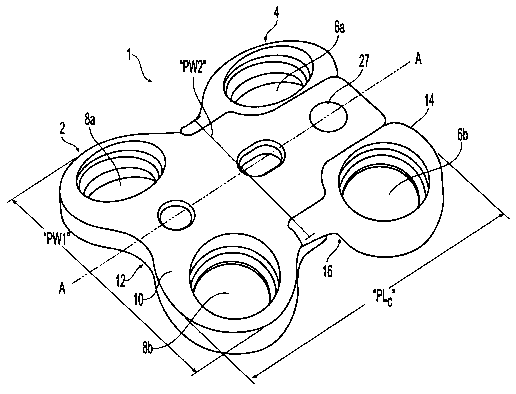
comprises a
polygonal shape, such as a hexagon, rectangle, or square. The recess 82 may
also take
the shape of a plurality of polygonal shapes, for example, two overlapping
hexagons may
comprise the shape of the recess 82 to form a combination-polygonal recess.
These
embodiments may be particularly useful in single-assembly plates with a
reduced area in
which to place a recess 82 for purposes of aligning a drill guide or similar
instrumentation.
An embodiment of a hexagon-shaped recess 82 is shown in Fig. 3d. While an
embodiment of a square-shaped recess 82 is shown in Fig. 3e. An embodiment of
a
translational plate assembly utilizing an overlapping hexagon-shaped recess 82
is shown in
Fig. 3f. The recess 82 may also serve a spacer-visualization function,
allowing the
surgeon to view the position of the intervertebral spacer after the plate 61
has been
installed.
[00109] A second recess 88 may be provided adjacent recess 82 and may be
configured to receive a temporary attachment pin (not shown) to temporarily
fix the plate 61
to at least one vertebral body while fastener holes are being drilled in the
bone. The pin
may have a sharpened tip to allow easy penetration into the bone cortex, and
the tip may
also have threads configured to affirmatively engage the bone.
-16-
NYJD: 1590358.1
CA 02578786 2007-03-01
WO 2006/028971 PCT/US2005/031333
82 may serve both the function of engaging the
engageable portion of a drill guide and receiving an attachment pin, as
described above. A
polygonal or combination-polygonal recess 82 may be especially useful for
these purposes,
with the attachment pin being of the appropriate shape and size to fit snugly
within at least
a portion of the recess 82 and into an appropriately shaped hole in a separate
plate.
[00111] Moreover, a motion-limiting shim 85 as shown in Figs. 3d-3f, may be
inserted into the recess 82, for limiting the translation of at least one
plate unit during use.
At least a portion of shim 85 may be shaped to fit in at least a portion of
the recess 82 so
that the shim 85 will not translate in the recess. Based on the shape of the
recess 82, the
shim 85 may be of a corresponding shape, similar to the attachment pin
described above.
At least a portion of the shim 85 extends down and blocks the pathway in which
the
carriage block moves. The recess 82 may be configured in that the shim 85 may
be
inserted at multiple locations so a user can adjust the amount of distance the
carriage
block may travel before the shim 85 would prevent further movement. The shim
85 being
inserted into the top of the bone plate may be easily used and implemented
during the
implant procedure since the top of the plate should be readily accessible. The
portion of
the shim 85 that contacts the carriage block may include a cantilevered
section or leaf
spring that will provide increased resistance to the movement of the carriage
block as the
carriage block translates until it has moved a predetermined distance at which
point the
shim 85 may prevent any further movement of the carriage block. At least a
portion of a
shim 85 should also be accessible to a user, so that the shim may be
removable. An
alternative embodiment of a motion-limiting shim is discussed infra in Fig. 9,
along with
greater detail of motion-limiting shims generally. The recess 82 and 88 as
well as the
motion-limiting shim 85 described in reference to plate 61 and shown in Figs.
3c-3f,
optionally may each individually or in combination be incorporated into the
bone plate 1
described supra.
[00112] Fig. 4a shows a plate 101 for use in a three level fusion procedure.
The
plate 101 may have a fixed plate portion 106 with first and second ends 108,
110 each
having a carriage block engaging portion 112,114, and a longitudinal axis C-C.
The fixed
plate portion 106 may have two pairs of bone fastener holes 116a, 116b; 118a,
118b for
engaging a pair of adjacent vertebrae. The first pair of bone fastener holes
116a,116b
may be round and thus may be used to rigidly fix the plate portion to the
underlying
vertebral body. The second pair of bone screw holes 118a, 118b may be slotted,
with
each hole having a slot axis "SA-SA" oriented substantially parallel to the
plate axis C-C.
The slotted holes 118a, 118b may have a slot length "SL" as measured from the
centroid
"X," "Y" of the circles that bound the ends of the holes 11 8a, 11 8b. The
slot length "SL"
may be from about 0.5 mm to about 10 mm.
-17-
NYJD: 1590358.1
CA 02578786 2007-03-01
WO 2006/028971 PCT/US2005/031333
11:[00113]" 11 .,.11!!:;11 IClpl1e S10tt6d8a, 118b may be configured to allow
the head 46 of an
associated bone screw to translate along the slot axis SA during operation.
This may allow
the adjacent vertebral bodies to translate with respect to each other along
the plate axis C-
C after the plate 101 has been attached to the vertebra using bone fasteners
40 inserted
through the round and slotted bone fastener holes 116a, 116b; 118a, 118b.
Thus, the slot
length SL may be dimensioned to allow a predetermined amount of translation
between the
vertebral bodies during operation. The slot length SL as measured between the
respective
centroids X, Y of the circles that define the slot ends 119a, 119b may be from
about 0.5
mm to about 10 mm.
[00114] As shown in detail in Fig. 4b, the slotted holes 118a, 118b may have
all the
features as previously described in relation to the round holes of Fig. 1 c,
including
appropriate features for receiving a retention clip 38 (see Fig. 2b) for
securing a bone
fastener 40 within the slotted hole 118a, 118b during use. Where retention
clips 38 are
used, the arms 48, 50 of the clips 38 may have a length "CL" sufficient to
engage the
groove 44 in fastener head 46 at any point along the length SL of the slotted
hole 118a,
118b. Thus, the retention clip 38 may have a length CL that is greater than
that of clips
used in the round bone screw holes 116a, 116b.
[00115] The plate 101 of Fig. 4a may further have first and second carriage
blocks
120, 122 engaged with respective first and second ends 108, 110 of the fixed
plate portion
106 to allow the plate 101 to engage third and fourth vertebral bodies. The
carriage blocks
120, 122 may have all of the features of the carriage blocks described above
in relation to
Figs.1 a-1 g and 3a-3f. Thus, each carriage block 120, 122 may have at least
one bone
fastener hole 124a, 124b; 126a, 126b for engaging an underlying vertebral
body, and may
have translating surfaces as described above in relation to Figs. 1a-1g and 3a-
3f to allow
the carriage blocks 120, 122 to translate with respect to the fixed plate
portion 106 along
the plate axis C-C within a predetermined amount, also as previously
described.
[00116] Fig. 5a shows a plate 128 for use in a three-level fusion procedure.
The
plate 128 may have a fixed plate portion 130 with first and second ends 132,
134 each
having a carriage block engaging portion 136, 138, and a longitudinal axis D-
D. The fixed
plate portion 130 may have one pair of round bone screw holes 140a, 140b for
rigidly fixing
the plate portion 130 to an underlying vertebral body. The plate 128 may
further have first
and second end carriage blocks 142, 144 engaged with respective first and
second ends
132, 134 of the fixed plate portion 130 to allow the plate 128 to translatably
engage second
and third vertebral bodies. The end carriage blocks 142, 144 may have any or
all of the
features of the carriage blocks described above in relation to the previous
figures, and
thus, each carriage block 142, 144 may have at least one bone fastener hole
146a, 146b;
148a, 148b for engaging an underlying vertebral body, and may have appropriate
translating surfaces configured to cooperate with the first and second ends
132, 134 of the
- 18-
NYJD: 1590358.1
CA 02578786 2007-03-01
WO 2006/028971 PCT/US2005/031333
(f~l~te"'f~o aMl~Jirithl~':!: ar"rA$k,}~õta~~~~k :;1142, 144 to translate with
respect to the fixed plate
portion 130 along the plate axis D-D within a predetermined range as
previously described.
[00117] The plate of Fig. 5a may also have an internal carriage block 150
disposed
between the bone screw holes 140a, 140b and end carriage block 144 to allow
the plate to
translatably engage a fourth vertebral body. As shown in greater detail in
Fig. 5b, the
internal carriage block 150 may have upper and lower surfaces 152, 154 and a
fastener
hole 156 in communication therewith. The internal carriage block 150 may
further have a
pair of side surfaces 158a, 158b; 160a, 160b configured to slidingly engage
corresponding
side surfaces 162a, 162b; 164a, 164b of a longitudinal recess 166 formed in
the fixed plate
portion 130. In one embodiment, the side surfaces 158a, 158b; 160a, 160b of
the internal
carriage block 150 may be "v"-shaped and may correspond to inverted "v"-shaped
side
surfaces of the recess 166. The "V-shaped arrangement of side surfaces 158a,
158b;
160a, 160b may traverse about 90% of the thickness "BT' of the carriage block,
which may
impart a degree of lateral flexibility to the carriage block to allow it to be
laterally
compressed to "snap" it into the recess 166, which may therefore facilitate
the insertion of
the carriage block 150 into a recess 166. The carriage block 150 may be
retained within
the recess by the interaction of the corresponding side surfaces 158, 162;
160, 164. The
carriage block 150 may further have compression and extension stop surfaces
168, 170
configured to engage corresponding surfaces 172, 174 of the recess 166. The
internal
carriage block 150 may have a length "ICL" and the recess 166 may have a
length "IRL."
In general, the length IRL will be greater than the length ICL to allow a the
internal carriage
block 150 to slide within the recess 166.
[00118] The internal carriage block 150 may slide within the recess 166 along
the
longitudinal axis of the plate "D-D" between the respective extension and
compression
stop surfaces 174, 172 of the plate 130. Length ICL may be from about 5 mm to
about 20
mm, while length IRL may be from about 7 mm to about 30 mm. As noted, the
lengths will
be selected to provide a desired amount of translation "TL" between the
carriage block and
the fixed plate portion to thus accommodate a desired translation between the
vertebrae
attached to the fixed plate portion 130 and the internal carriage block 150.
The translation
may preferably be from about 5 mm to about 25 mm.
[00119] It is noted that although the illustrated embodiment comprises
corresponding "Y-shaped surfaces, the side surfaces of the screw carriage and
slot may
assume any shape appropriate to allow the desired longitudinal sliding while
preferably
preventing the carriage from disengaging from the slot. Thus, dovetail
surfaces, "u"-
shaped surfaces, mortise-and-tenon surfaces, channels, grooves, ridges, etc.
may also be
used as desired.
[00120] The fastener hole 156 of the internal carriage block 150 may have all
the
features as previously described in relation to the round holes of Fig. 1c, or
the slotted
-19-
NYJD: 1590358.1
CA 02578786 2007-03-01
WO 2006/028971 PCT/US2005/031333
IIrydIC~s-f'af F~~s~; 4W41x''iAV;Qd~r~g;;Ioppropriate configurations for
receiving a retention clip 38
(see Fig. 2b) to secure a bone fastener 44 (see Fig. 2a) within the hole 156
during use.
[00121] Fig. 5c shows a two-piece internal carriage block 178 that may be used
with
the plate 128 of Fig. 5a. The two-piece carriage block 178 may be divided
substantially
into halves 180a, 180b along the block longitudinal axis "E-E." The block
halves 180a,
180b may be disassembled, shifted longitudinally with respect to each other,
nested
together, and installed within the plate recess 166 in the nested state. Once
they have
been installed in the recess 166, the halves 180a, 180b may be realigned and
fit back
together to form a unitary piece. The retention clip 38 may then be installed
within the
appropriate groove 182a, 182b in the block halves 180a, 180b and may function
to
maintain the halves together during operation. This configuration eliminates
the need to
provide a"flexible" internal carriage block with indents 176a, 176b, and may
provide a
carriage block that is easier to machine and assemble.
[00122] The plate 184 of Fig. 6 may be used in a four-level fusion procedure
and
may have a plate portion 186, first, second and third internal carriage blocks
188, 190, 192
and first and second ends 194, 196 for engaging a pair of end carriage blocks
198, 200 in a
manner similar to that described in relation to the plate of Fig. 5a. The
plate portion 186
may have a longitudinal axis F-F, and may have first, second and third
intermediate
recesses 202, 204, 206 disposed along the axis F-F for cooperating with the
first, second
and third internal carriage blocks 188, 190, 192, respectively. It is noted
that while the
plate 184 is shown for use in a four-level fusion procedure, it could easily
be configured for
use in a three or two-level procedure simply by shortening the plate and
providing fewer
internal carriage blocks. Likewise, the plate portion 186 could be provided
with one or
more sets of holes, preferably slotted holes, in lieu of one or more of the
internal carriage
blocks.
[00123] In addition, the internal carriage blocks 188, 190, 192 may have any
or all of
the features described in relation to the plate 128 of Fig. 5a, and the end
carriage blocks
198, 200 may have any or all of the features described in relation to Figs. la-
5c.
[00124] The plate 208 of Fig. 7a combines some of the features of the
previously
described plates into a single plate for use in a four-level spinal fusion
procedure. The
plate 208 may have a fixed plate portion 210 with first and second ends 212,
214, one pair
of round holes 216a, 216b for engaging a first vertebra, one pair of slotted
holes 218a,
218b for engaging a second vertebra, one internal carriage block 220 disposed
in recess
222 for engaging a third vertebra, and a pair of end carriage blocks 224, 226,
each
configured to engage a respective end 212, 214 of the fixed plate portion 210.
Thus
configured, the plate 208 may be rigidly fixed to the first vertebra, while
the remaining
vertebrae may translate with respect to the first vertebra via the slotted
holes 218a, 218b,
internal carriage block 220, and end carriage blocks 224, 226 as previously
described.
-20-
NYJD: 1590358.1
CA 02578786 2007-03-01
WO 2006/028971 PCT/US2005/031333
di, holes may be configured similarly to that described in
relation to Figs. 1 c and/or 4a-4b, and may have retaining clips 38 configured
to retain a
bone screw 44 therein.
[00125] Figs. 7b-7c show a similar single plate for use in a four-level spinal
fusion
procedure, but without an internal carriage block 220. Instead, the
embodiments of Figs.
7b-7c have two pairs of slotted holes 218a, 218b and 218c, 218d.
[00126] Fig. 8a shows a plate 228 for use in a two-level fusion procedure, the
plate
having a two-piece sandwich style plate portion 230 comprising a track base
1000 and top
plate 2000. The plate portion 230 engages three carriage blocks 300a, 300b,
300c via
respective recesses 1116a, 1116b, 1116c formed in the track base 1000.
[00127] The carriage blocks 300a, 300b, 300c each may include one or more
fastener holes 340a, 340b, 340c configured to receive fasteners 44 to fix the
carriage
blocks to associated vertebrae. The track base 1000 may have first and second
ends
1020, 1040 and may have a curved profile to allow the plate 228 to more
closely match the
contour of the patient's spine. The top plate 2000 may likewise have first and
second ends
2020, 2040 and may have a curved profile that substantially matches that of
the track base.
[00128] The top plate 2000 may have a pair of lateral alignment flanges 1022,
1024
and at least one bore 2060 for receiving a holding fastener 400 for securing
the top plate
2000 to the track base 1000. Any appropriate fastening means may be provided
to fix the
top plate to the track base, including but not limited to screws, rivets,
press-fit, laser
welding, brazing, or suitable adhesives. The alignment flanges 1022,1024 may
serve to
align the top plate and track base, and to provide the plate 228 with
increased strength in
bending and torsion.
[00129] The top plate 2000 and track base 1000 may be assembled so as to
retain
the carriage blocks 300a, 300b, 300c within associated recesses 11 16a, 1116b,
1116c so
that the carriage blocks may slide within the recesses, thus providing the
desired
translation capability between the engaged vertebrae. The carriage blocks
engage the
respective recesses via reduced-size central portions 1350a, 1350b, 1350c.
[00130] Two-hole carriage blocks 300a, 300b, 300c may be provided, and as
previously described in relation to the plate of Fig. 1 a, the carriage block
fastener holes
340a, 340b, 340c, may be configured to receive retention clips 38 (see Fig.
2b) for
retaining the bone fasteners 44 (see Fig. 2a) in the holes during operation.
Fig. 8b shows
the plate of Fig. 8a in the assembled position.
[00131] Figs. 8c-8f show carriage block 300 in greater detail. As illustrated
in Figs.
8c and 8d, carriage block 300 may comprise a pair of fastening portions 370a,
370b and a
connecting portion 350 disposed therebetween. The connecting portion 350 may
have first
and second ends 392a, 392b, which may be configured to conform to
corresponding
outside and inside walls 1117a, 1117b of an associated plate recess 1116a,
1116b, 1116c
-21-
NYJD: 1590358.1
CA 02578786 2007-03-01
WO 2006/028971 PCT/US2005/031333
irtth.;;WFiicHl,tti~ %,,#ill fit. In the illustrated embodiment, connection
portion
350 has a concave first end 392a to engage a correspondingly curved recess end
(outside
wall 1117a or inside wall 1117b, see Fig. 8a).
[00132] The carriage block 300 of Figs. 8e and 8f have fastener holes 340 that
may
be offset longitudinally from the center of the connecting portion 35 by a
length OL. This
offset ensures that in use, the outer edges 390a, 390b of the carriage block
30 will not
extend beyond the ends 2020, 2040 of the top plate 2000, even where the plate
and
carriage blocks are in the fully compressed configuration. Such an arrangement
provides
the advantage that it prevents any portion of the top plate 2000 from
protruding either into
or undesirably close to the adjacent disc space when the carriage blocks
translate fully
within their associated recesses.
[00133] The carriage block 300 may have compression and extension surfaces
392a, 392b configured to engage corresponding surfaces 1117a, 1117b of the
associated
recess 1116 formed in track base 1000. Thus configured, the connecting
portions 350 of
the carriage blocks 300a, 300b, 300c may be received within the corresponding
recesses
1116a, 1116b, 1116c in the track base 1000 and may translate along the plate
to provide
the desired translation of adjacent vertebral bodies.
[00134] Fig. 8g shows an alternative carriage block 90 having'three fastener
holes
92a, 92b, 92c, that may be used with a plate such as the plate 61 shown in
Fig. 3a.
Fastener hole 92c may be offset from fastener holes 92a, 92b and may be
disposed
substantially along the longitudinal axis B-B of the plate 61. The additional
fastener hole
92c may increase the retention of the plate with the associated vertebral
body. This may
be particularly advantageous where the plate is subjected to significant
forces and
moments in use which may tend to pull the fastener out of engagement with the
bone.
[00135] The plate engaging portion 94 of the three-hole carriage block 90 may
be
slidably received within a plate, such as the carriage block-engaging portions
70, 72 of the
plate 61 as previously described in relation to carriage blocks 74, 76. The
plate engaging
portion 94 may also comprise extension and compression stop surfaces 96, 98
similar to
those described in relation to blocks 74, 76 to limit the total movement of
the carriage block
90 along axis B-B with respect to the fixed plate portion 61. The extension
and
compression ranges of movement and resistance to movement may be the same as
for the
previously described carriage blocks.
[00136] In order provide the surgeon the option to limit or prevent pre- or
post-
implantation translation of any or all of the carriage blocks described herein
(such as
elements 4, 74, 76, and 300) for use with any plate or plate element described
herein, a
motion limiting shim 500, shown in Fig. 9, may be provided. Shim may be
positioned
between the carriage block 300 and one of the sides 1117a,1117b of the
associated
recess 1116a, 1116b, 1116c. Such an arrangement may allow the surgeon to
customize
-22-
NYJD: 1590358.1
CA 02578786 2007-03-01
WO 2006/028971 PCT/US2005/031333
f,;;-Oiz)ation of one or more of the carriage blocks. The shim
il1h:e: 'a"rn.ou'h't'anUIldireCff0'q0
500 may be made of a flexible material, such as elgiloy or nitinol, or may be
made of a
suitable bioresorbable material. Shim 500 is preferably composed of a
biocompatible
material. As illustrated in Fig. 9, the shim 500 may have opposing flexible
tabs 520a, 520b
that may allow an operator to compress the shim to position it within the
targeted recess
1116. In particular, flexible tab 520a may be actuated by applying pressure to
bulbous tab
560. Shim 500 may have a height "SH" that may be the maximum distance a shim
may
occupy along the longitudinal axis of a plate. Moreover, shim 500 may have
gripping tabs
522a, 522b that may allow an surgeon to grip the shim 500 to move it to a
desired location
within a plate, or remove it completely from a plate. Side surfaces 524a, 524b
may
correspond to the outer edges of a flange 1022 (see infra Fig. 10), or may
generally
correspond to a translating surface of a carriage block and/or plate segment,
depending at
least in part how shim 500 is situated in relation to a carriage block and/or
plate segment.
[00137] Fig. 10 illustrates a plate having a cam-compression feature for use
with
any of the previously described plates. This feature is operable to allow the
surgeon to
adjust the recess length to minimize or prevent translation of the associated
carriage block,
or to induce a compression force between adjacent vertebrae to aid in seating
a spinal
fusion implant inserted therebetween.
[00138] The cam 1140 may be elliptical, with an arcuate camming surface 1142
configured to correspond to an arcuate surface 392 on the connecting portion
350 of the
associated carriage block 300 (see, e.g., Fig. 8c). The cam 1140 may have an
unactuated
position in which the cam major diameter is oriented substantially
perpendicular to the
longitudinal axis of the plate, and an actuated position in which the cam
major diameter is
oriented substantially parallel with respect to the longitudinal axis of the
plate. The
unactuated cam position may correspond to a maximum recess length SM, while
the
actuated position may correspond to a minimum recess length S2.
[00139] Thus, prior to fixing the carriage blocks to the adjacent vertebrae,
the cam
1140 may be rotated sufficiently to shift the adjacent carriage block 300 in a
first direction
toward the one of the walls 1117b of the recess 1116, thus minimizing or
eliminating the
gap between the inside wall and the connecting portion 350 of the carriage
block 300.
Once the cam 1140 position is set, the carriage blocks 300 may then be fixed
to the
adjacent vertebrae to provide a translation plate having, if desired, a
reduced translation
length for each carriage block 300. This provides the benefit of allowing the
surgeon to
easily adjust the amount of translation desired for each level of fixation to
suit the anatomy
and physiology of the individual patient.
[00140] The cam 1140 may also be used to induce a compression force between
adjacent vertebrae to aid in seating a spinal fusion implant inserted
therebetween. Thus,
first and second carriage blocks 300a, 300b may be fixed to adjacent vertebrae
with the
-23-
NYJD: 1590358.1
CA 02578786 2007-03-01
WO 2006/028971 PCT/US2005/031333
Ilc~m"~'14(fiõi'hl!;tiH~l-~iafa~Ct~i~~i~~;;~t~ix~pn. Thereafter, the cam 1140
may be rotated to the
actuated position, which may shift the first carriage block 300a toward the
second carriage
block 300b. This movement may cause the underlying vertebra to move with the
first
carriage block 300a toward the second carriage block 300b, thus reducing the
space
between the vertebrae and applying a compressive force between the vertebral
end plates
and a spinal fusion spacer placed therebetween.
[00141] As can be seen in Fig. 10, dashed line "DL" shows the expected
position of
the carriage block 300 after a single 90-degree rotation of the cam 1140. To
achieve this
expected position, carriage block 300 would move a longitudinal distance S1
toward the
center flange 1022. Further rotation of the cam 140 would move the carriage
block 30 a
second distance S2, until the second end 390B of the carriage block 300 abuts
the center
flange 1022 of the top plate 20.
[00142] The cam 1140 may be secured to the track base 1000 with a holding
fastener 400 or any other appropriate fastening method. In one embodiment, the
fastener
may serve both to secure the cam 1140 to the track base 1000 and to provide a
means of
actuating the cam. Thus, the fastener 400 may have a recess suitable for
receiving a
driving and/or adjusting tool.
[00143] Fig. 11 shows a plate 232 for use in a corpectomy procedure, in which
at
least a portion of at least one vertebral element is removed. Thus, the plate
232 spans the
space left by the removed element or elements. Plate 232 may have a plate
portion 234
with first and second ends 236 configured to cooperate with a pair of end
carriage blocks
238, 240. In the illustrated embodiment, end carriage block 238 has a third
plate hole as
previously described in relation to Fig. 8g. Plate 232 further comprises a
pair of elongated
viewing windows 242, 244 suitable to allow the surgeon to visualize a
corpectomy graft
placed between the affected vertebrae. The plate 232 of Fig.11 may further
incorporate
any or all of the features previously described in relation to the embodiments
of Figs. 1a-10
(e.g., plate and carriage block curvatures, straight and offset carriage
blocks, shim
arrangements, cam features, fastener locking clips, etc.)
[00144] Figs. 12a and 12b show a plate 900 that may be provided in two
extensible
pieces 901, 908, which may allow the plate itself to bear a portion of the
translation. This
extensible two-piece design also may allow the surgeon to adjust the length of
the plate to
fit the anatomy of a particular patient. Thus first extensible piece 901 may
have a first end
903 engaged to a first carriage block assembly 300a, and a second end 905
configured to
be telescopically received within a first end 907 of the second extensible
piece 908.
Likewise, the second extensible piece 908 may have a first end 907 configured
for
telescopic engagement with the first piece 901 and a second end 909 engaged to
a second
carriage block assembly 300b. The second extensible piece 908 may have a
locking
device 906, which may lock the relative positions of the first and second
pieces. In the
-24-
NYJD: 1590358.1
CA 02578786 2007-03-01
WO 2006/028971 PCT/US2005/031333
(J-1'WtYOteifJ,&h'dpdevice 906 is an elliptical cam associated with both the
first and second plate portions 901, 908. The cam 906 may have a major
diameter
substantially aligned with the longitudinal axis K-K of the plate 900 when in
the unlocked
position, such that rotating the cam 906 slightly may configure it to the
locked position,
thereby fixing the pieces 901, 908 together. After adjustment of first
extension piece 901
and second extension piece 908, the pieces may be fixed together so that they
will not
move relative to each other upon implantation in the spine. Thus, it is
intended that upon
implantation, first extension piece 901 will not move relative to second
extension piece 908
in situ. Meanwhile, carriage blocks 300a, 300b would provide for in situ
movement relative
to the first and second extension pieces 901, 908, and to each other. upon
implantation of
the plate 900. Fig. 12a shows plate 900 in a closed or compressed position,
while Fig.
12b shows the plate 900 in an open or extended position. As with the previous
embodiments, the plate of this embodiment may comprise any or all of the
applicable plate
and carriage block features described in relation to all previous embodiments.
Further, the
plate of this embodiment may be used for single or multiple-level corpectomy
or fusion
procedures or combinations thereof.
[00145] Figs. 13a and 13b show another embodiment of a fixation assembly 600
including a plate 602 with dovetail portions 612 configured to receive at
least a portion of a
carriage block 604. In this embodiment, carriage block 604 is allowed to
initially engage a
dovetail portion 612, and thereafter the end 622 of the dovetail portion 612
is deformed at
or near the end 617 of the carriage block 604 to effectively limit the motion
of the carriage
block and prevent it from disengaging with the plate 602. End 622 may be
deformed by
any suitable method, including swaging.
[00146] Plate 602 may have fastener holes 606a, 606b, 608a, 608b, 610a, 610b,
which may be circular or slot-shaped. Moreover, plate 602 may include any or
all of the
characteristics of previously described plates, including clips, recesses,
internal carriage
blocks, etc.
[00147] Carriage block 604 may translate along dovetail portion 612 in use,
which
may be limited by the deformed end 622 in one direction, and a stop surface
614 in another
direction. As described in more detail above, carriage block 604 may translate
in situ, with
or without fasteners 660 inserted into fastener hole 616a, 616b, which may
provide
locations for inserting fasteners 660 into a bone segment.
[00148] As shown in detail in Fig. 13b, carriage block 604 may have
translation
surfaces 618, and plate 602 may have translation surfaces 620. As described in
more
detail above, as carriage block 604 translates with respect to plate 602,
translation
surfaces 618, 620 may slidingly engage, and may create a variable amount of
friction along
the length of the dovetail portion 612. As with plate 602, carriage block 604
may include
any or all of the characteristics of carriage blocks described above.
-25-
NY1D: 1590358.1
CA 02578786 2007-03-01
WO 2006/028971 PCT/US2005/031333
11001491" I06uetaiC;ip:6rH66,l0,'~i2 may have a variety of shapes and sizes,
based in part
on the desired strength of the assembly 600. For instance, it may be
beneficial to have a
wider, and overall larger, dovetail portion 612 where the expected in situ
forces on the
assembly 600 are expected to be substantial.
[00150] Figs. 14a-14b are perspective views of yet another embodiment of a
fixation
assembly 700 having a plate 702 and carriage blocks 704a, 704b. Plate 702 may
have a
window 707 for increased visualization, and at least one fixation hole 710
with at least one
drill guide key 711 disposed adjacent to the fixation hole 710. Similarly,
carriage blocks
704a, 704b may also have fixation holes 713 and drill guide keys 714. Drill
guide keys
711, 714 may receive at least a portion of a drill guide (not shown), and may
assist in
aligning a drill barrel (not shown) with a fixation hole.
[00151] In this embodiment, plate 702 has ends 703, and may engage carriage
blocks 704a, 704b at tapered engaging surfaces 706a, 706b, respectively. Ends
703 of
plate 702 may be shaped and/or formed such that carriage blocks 704a, 704b are
prevented from sliding off the plate 702. As seen in Fig. 14a, carriage blocks
704a, 704b
are in a compressed condition, whereby the assembly 700 may be in its shortest
configuration along its longitudinal axis. Fig. 14b shows the assembly 700 in
an expanded
condition, whereby carriage blocks 704a, 704b each have translated along
tapered
engaging surfaces 706a, 706b, respectively, and in the direction of the
adjacent arrows. In
this configuration, the overall length of assembly 700 may be greater along
the longitudinal
axis, as compared to the configuration shown in Fig. 14a.
[00152] The tapered engaging surface 706b is shown in more detail in Fig. 15.
As
seen in this embodiment, tapered engaging surface 706b has side tapered
surfaces 708a,
708b, with a substantially flat surface 709 disposed therebetween. Side
tapered surfaces
708a, 708b may be progressively tapered, such that the resistance between a
carriage
block 704b and the tapered engage surface 706b increases as the carriage block
704b
(not shown, for clarity) attempts to translate toward the center of plate 702.
The result of
such an arrangement may be that it requires more force to compress assembly
700, than is
required to lengthen assembly 700. As further seen in Fig. 15, plate 702 may
also have
stops 716, which may limit the movement of carriage block 704b relative to the
plate 702.
[00153] An embodiment of a carriage block 704 is shown in Fig. 16, wherein
carriage block 704 may have fixation holes 713 and drill guide keys 714, as
also shown in
Figs. 14a-15. As also seen in this embodiment, carriage block 704 may have a
contoured
opening 720 having tapered surfaces 721, 722 for engaging a tapered engaging
surface
706 of plate 702, and disposed between lobes 725. Carriage block 704 may
engage a
tapered engaging surface 706 of plate 702 in such a way that as carriage block
704 is
urged toward the center of plate 702 (i.e. toward a more compressed
condition), carriage
block 704 flexes such that lobes 725 are pushed upward by the tapered engaging
surface
-26-
NYJD: 1590358.1
CA 02578786 2007-03-01
WO 2006/028971 PCT/US2005/031333
7706 Qf'pf~'~td '~iD2!!Af..tYie:ltd,piwW; 6b, gaging surface 706 is contoured
to provide progressive
resistance, the carriage block 704 may experience greater flexure as it is
progressively
urged closer to the center of plate 702. As such, carriage block 704 may be
constructed of
a resilient material which may flex back upon the movement of the carriage
block 704 away
from the center of the plate 702 and toward the end 703 of plate 702 (i.e.
toward a more
expanded condition).
[00154] Progressive resistance of a tapered engaging surface 706 may be
achieved
by increasing the angle of tapered side surfaces 708a, 708b along the
longitudinal axis of
plate 702. Progressive resistance may also be achieved by surface roughening.
Other
methods will be appreciated by those skilled in the art.
[00155] Another embodiment of a fixation assembly 800 is shown in Figs. 17a-
17b.
In this embodiment, plate 802 may have a plurality of windows 807, and two
sets of fixation
holes 810a, 810b, wherein fixation holes 810a may be substantially slot-
shaped, and
fixation holes 810b may be substantially circular. Fasteners 830 may be
configured to
translate within slot-shaped holes 810a. Plate 802 may also have ends 803, and
tapered
engaging surfaces 806 with carriage blocks 804a, 804b disposed thereon.
Carriage blocks
804a, 804b may again have fixation holes 813 for receiving a fastener 830.
Plate 802 and
carriage blocks 804a, 804b may also each have drill guide keys 811, 814 for
the same
purposes as discussed above in relation to Figs. 14a-14b. Fastener 830 may be
a screw.
[00156] Assembly 800 may also initially have tabs 825a, 825b disposed between
carriage blocks 804a, 804b and plate 802. In use, tabs 825a, 825b may serve to
space
carriage blocks 804a, 804b toward ends 803, which may configure assembly 800
in an
expanded condition. This may be advantageous for implantation purposes, as it
may be
beneficial to install assembly 800 into a patient with the assembly 800 in an
expanded
condition. Tabs 825a, 825b are shown to be removed in Fig. 17b. In this
embodiment,
carriage block 804b has translated completed toward the center of the plate
802, in the
direction of the adjacent arrow. In contrast, carriage block 804a has not
translated,
revealing a portion of the tapered engaging surface 806a and stops 816 of
plate 802. As
such, the embodiment of Fig. 17b is in a partially expanded (or partially
compressed)
condition. In use, a surgeon preferably will remove tabs 825a, 825b after
implanting
assembly 800 in a patient. Tabs 825a, 825b may be disposable.
[00157] It is expressly contemplated that progressive resistance may be
utilized with
all embodiments as shown herein, as will be appreciated by those of skill in
the art.
Moreover, it is contemplated that the components and features of one
embodiment may be
combined and/or substituted for similar components in another embodiment.
Lastly,
progressive resistance may be provided in any suitable direction and/or
pattern. For
instance, a tapered engaging surface 706, 806 may be tapered such that
progressive
-27-
NYJD: 1590358.1
CA 02578786 2007-03-01
WO 2006/028971 PCT/US2005/031333
rriage block 704, 804 translates toward the end 703, 803 of
the plate 702, 802, instead of toward the center of the plate 702, 802.
[00158] It should be noted that the aforementioned descriptions and
illustrations
have been provided as examples of the configurations of translation plates
that may be
designed and assembled using the principles of the invention. These examples
will be
understood to one of ordinary skill in the art as being non-limiting in that a
translating plate
employing one or more of the disclosed features may be produced as desired or
required
for a particular patient's need. Thus, the features disclosed are "modular" in
nature.
[00159] For example, the plate itself may be provided in either the one-piece
design
of Figs. 1 a-7c, or the two piece design having a top plate and track base of
Fig. 8a-8b.
The one or two piece plate designs also may be provided with integral screw
holes (Figs.
1 a-7c) to allow the plate element itself to be screwed to an underlying
vertebra, or they
may not have integral screws holes (Figs. 8a-8g and 10-12b) such that the
plate itself
engages the underlying vertebrae only via the carriage blocks.
[00160] Furthermore, the one or two piece plates may employ any combination of
carriage block designs desired (e.g. offset type (Figs. 8e-8f), non-offset
type (Figs. 8c-8d),
third-hole type (Fig. 8g) or internal type (Figs. 5a-5c, 6, 7a)).
[00161] Each of the fasteners and fixation plates disclosed herein may be
formed of
a titanium alloy such as titanium-aluminum-niobium, which may be anodized. One
material
for use with each of the plates and screws described herein is Ti-6AI-7Nb,
with a density of
about 4.52 gm/cc, a modulus of elasticity of about 105 GPa, an ultimate
tensile strength of
about 900 MPa, and a yield strength of about 800 MPa. Surfaces of the
fasteners may
also be burr free, with all sharp edges having a radius to a maximum of about
0.1 mm.
Further, the retention clips 38 may be fabricated from titanium, titanium
alloy, or elgiloy.
[00162] While the invention has been shown and described herein with reference
to
particular embodiments, it is to be understood that the various additions,
substitutions, or
modifications of form, structure, arrangement, proportions, materials, and
components and
otherwise, used in the practice and which are particularly adapted to specific
environments
and operative requirements, may be made to the described embodiments without
departing
from the spirit and scope of the present invention. Accordingly, it should be
understood
that the embodiments disclosed herein are merely illustrative of the
principles of the
invention. Various other modifications may be made by those skilled in the art
which will
embody the principles of the invention and fall within the spirit and the
scope thereof.
-28-
NY1D: 1590358.1