Note: Descriptions are shown in the official language in which they were submitted.
CA 02579658 2007-03-09
WO 2006/029290
PCT/US2005/032093
-1-.
APPLICATION OF ABNORMAL EVENT DETECTION TECHNOLOGY
TO OLEFINS RECOVERY TRAINS
BACKGROUND OF THE INVENTION
[0001] The present invention relates to the operation of an ethylene plant.
In particular, the present invention relates to determining when the ethylene
plant is deviating from normal operation.
[0002] In the petrochemical industry, an Olefins Recovery Train (ORT) is a
very important process for an ethylene plant. The ORT purifies ethylene and
, propylene and also recovers by-products of the olefins production plant. Due
to
the complicated dynamic nature and cryogenic portions of the ORT, abnormal
process operations can easily result from many root problems that cause the
ORT operation to deviate from the normal operating state. Abnormal operations
of the ORT can have significant economic implications and, in many cases, can
stop production. These abnormal situations can cause lost production,
equipment damage, environmental emissions, injuries and fatalities. A primary
job of the console operator is to identify the cause of the abnormal situation
and
execute compensatory or corrective actions in a timely and efficient manner.
[0003] The current commercial practice is to use advanced process control
applications to automatically adjust the process in response to minor process
disturbances. For moderate to severe abnormal operations, the current practice
is
to rely on human process intervention. And for very severe abnormal
operations,
the current practice is to use automatic emergency shutdown (ESD) systems that
can have substantial economic consequences for the process equipment.
[0004] Currently, the console operator is notified of an abnormal condition
via process alarms. These alarms are triggered when key process measurements
(temperatures, pressures, flows, levels, compositions, valve positions, etc.)
CA 02579658 2007-03-09
WO 2006/029290
PCT/US2005/032093
- 2 -
violate a pre-defined set of operating ranges. These operating ranges are
often
static values from initial designs or frequently adjusted values by console
operators to envelop important operating regions. For highly integrated
processes, such as ORT, the alarm system effectiveness is an often difficult
balance of providing timely alarms during normal operation (early warning) and
preventing "alarm floods" during abnormal operation (risk of high priority
information being missed). Thus, the current notification technology is
challenged to provide sufficient early notifications while generating an
acceptable rate (near zero) of false notifications to ensure the alarm system
remains effective during severe abnormal operation.
[0005] There can be many thousands of process measurements that cover
the operation of a typical ORT, of which hundreds are considered key to normal
operation. In addition, each process measurement can have as many as 15
different alarms being configured. Under a conventional Distributed Control
System (DCS) like Honeywell's TDC3000, the operator must survey this list of
sensors and its trends, compare them with mental knowledge of normal ORT
operation, and discover the potential problems early enough to intervene
before
significant disruptions can occur. Due to the very large number of sensors in
an
operating ORT, abnormalities can be easily missed. With the current DCS based
monitoring technology, the only automated detection assistance an operator has
is the DCS alarm system which is based on the alarming of each sensor when it
violates predetermined limits. Due to the complexity of an ORT, this type of
notification often comes in too late to allow the operator to have sufficient
time
to take preventive action to mitigate a problem. Over-use of the alarm system
for early detection can have even worse consequences. The alarms become an
annoyance to the operator during normal operation and the operator ignores the
alarm system. During abnormal conditions, the operator becomes flooded with
alarms and misses critical information. The present invention provides a more
effective notification to the operator of the ORT.
CA 02579658 2007-03-09
WO 2006/029290
PCT/US2005/032093
- 3 -
SUMMARY OF THE INVENTION
[0006] The present invention is a method for detecting an abnormal event
for some process units of an ethylene processing system. The system includes a
number of process units. The method compares the current operations of some
of the process units to a model of normal operation for those units. If the
difference between the current operation of the unit and the normal operation
indicates an abnormal condition in a process unit, then the cause of the
abnormal
condition is determined and corrective action can be taken.
BRIEF DESCRIPTION OF THE DRAWINGS
[0007] Figure 1 shows how the information in the online system flows
through the various transformations, model calculations, fuzzy Petri nets and
consolidation to arrive at a summary trend which indicates the normality/
abnormality of the process areas.
[0008] Figure 2 shows a valve flow plot to the operator as a simple x-y
plot.
[0009] Figure 3 shows three-dimensional redundancy expressed as a PCA
model.
[0010] Figure 4 shows a schematic diagram of a fuzzy network setup.
[0011] Figure 5 shows a schematic diagram of the overall process for
developing an abnormal event application.
[0012] Figure 6 shows a schematic diagram of the anatomy of a process
control cascade.
[0013] Figure 7 shows a schematic diagram of the anatomy of a
multivariable constraint controller, MVCC.
CA 02579658 2007-03-09
WO 2006/029290
PCT/US2005/032093
- 4 -
[0014] Figure 8 shows a schematic diagram of the on-line inferential
estimate of current quality.
[0015] Figure 9 shows the KPI analysis of historical data.
[0016] Figure 10 shows a diagram of signal to noise ratio.
[0017] Figure 11 shows how the process dynamics can disrupt the
correlation between the current values of two measurements.
[0018] Figure 12 shows the probability distribution of process data.
[0019] Figure 13 shows illustration of the press statistic.
[0020] Figure 14 shows the two-dimensional energy balance model.
[0021] Figure 15 shows a typical stretch of Flow, Valve Position, and Delta
Pressure data with the long period of constant operation.
[0022] Figure 16 shows a type 4 fuzzy discriminator.
[0023] Figure 17 shows a flow versus valve Pareto chart.
[0024] Figure 18 shows a schematic diagram of operator suppression logic.
[0025] Figure 19 shows a schematic diagram of event suppression logic.
[0026] Figure 20 shows the setting of the duration of event suppression.
[0027] Figure 21 shows the event suppression and the operator suppression
disabling predefined sets of inputs in the PCA model.
CA 02579658 2012-01-11
- 5 -
[0028] Figure 22 shows how design objectives are expressed in the primary
interfaces used by the operator.
100291 Figure 23 shows the operator overview of the ORT operation
decomposed into 12 individual monitors; 11 key operational sections and a flow
versus valve monitor.
[00301 Figure 24 shows the Methanator and 1120 Driers area monitor has a
warning alert.
[00311 Figure 25 shows the result of clicking on the triangle in
Figure 24; a Pareto chart indicating the residual of sensor SP125 is outside
its
tolerance limit.
[00321 Figure 26 shows that clicking on the Multi-Trend button brings up
the trends of the value and model predictions of the sensors in the
Pareto chart of Figure 25.
[00331 Figure 27 shows a Pareto ranking of the valve-flow models based on
normalized-projection-deviation error.
[0034] Figure 28 shows the details of the valve-flow model obtained by
clicking on any bars from the bar chart of Figure 27.
[0035] Figure 29 shows the Fuzzy Logic networks for several procedural-
induced abnormal conditions.
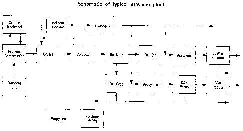
[0036] Figure 30 shows a schematic diagram of a typical ethylene plant.
CA 02579658 2007-03-09
WO 2006/029290
PCT/US2005/032093
- 6 -
DETAILED DESCRIPTION OF THE PREFERRED EMBODIMENTS
[0037] The present invention is a method to provide abnormal event
detection (AED) to the operator that sections of an ethylene plant are not
functioning properly. The present invention will be discussed with specific
references to a successful application of the invention for demonstration only
but
not limitation.
[0038] The method uses fuzzy logic (see Appendix 1, Section Deploying
PCA Models and Simple Engineering Models for AED) to combine multiple
supportive evidence of abnormal situations that contribute to an operational
problem and estimates its probability in realtime. The probability is
presented in
a continuous format to alert the operator using a single trend for a
processing
area of the plant. This method includes a set of tools that allow the operator
to
drill down to the root cause of a problem for focused action. This approach
has
been demonstrated to provide the operator with an advanced warning of the
abnormal operation that can be minutes to hours sooner than the alarm system.
This advanced warning allows the operator to take corrective action sooner and
prevents escalation of the event. This method has been successfully applied to
an olefins recovery train (ORT).
[0039] The ORT application uses specific operational knowledge of ORT
operations to combine indications from Principal Component Analysis and
engineering models, and relevant sensor readings into a fuzzy logic network as
shown in Figure 4. This fuzzy logic network aggregates the evidence and
indicates the confidence level of a potential problem. Therefore, the network
can detect a problem with higher confidence at its early stage and provide
valuable time for the operator to make compensatory or corrective actions to
avoid an ORT operational incident. This is a key advantage over the present
commercial practice of monitoring ORT based on single sensor alarming from a
CA 02579658 2007-03-09
WO 2006/029290
PCT/US2005/032093
- 7 -
DCS system because more often the alarm comes in too late for the operator to
mitigate an operational problem due to the complicated dynamic and cryogenic
nature of operating an ORT.
[0040] The ethylene recovery train is divided into equipment groups
(referred to as key functional sections or operational sections). These
equipment
groups may be different for different ethylene recovery trains depending on
its
design. The procedure for choosing equipment groups which include specific
process units of the ethylene recovery train is described in Appendix 1.
[0041] Figure 30 shows a schematic diagram of a typical ethylene plant that
was used to demonstrate the present invention. In the preferred embodiment for
this plant, the present invention divides the ORT operation into key
operational
sections (see Appendix 1, section Developing PCA Models for AED). The
example ethylene plant was divided into eleven sections as follows:
1. Charge Gas Compressor
2. Drier, Cold Box, and Methane Booster
3. Ethylene and Propylene Refrigeration
4. De-Methanizer
5. De-Ethanizer
6. Acetylene Converter
7. C2 Splitter
8. Methanator and H20 Drier
9. De-Propanizer
10. MAPD Hydrofiner
11. C3 Rerun and Propylene Fractionator
[0042] Besides monitoring the key operational areas, this invention also
monitors the consistency between control valve position and flow for a set of
key control valves (see Appendix 1, section Simple Engineering Models for
CA 02579658 2007-03-09
WO 2006/029290
PCT/US2005/032093
- 8 -
AED). This invention also provides suppression of model calculations to
eliminate false positives on special cause operations and enables the operator
to
selectively remove sensors from the models in the event that the sensor is out
of
service.
A. Operator Interface
[0043] The display is intended to give the operator a view of the
probability
that there is an abnormal event affecting the process unit.
[0044] Figure 23 shows the operator display of the decomposition of the
ORT operation into eleven key operational sections and a control valve
position
versus flow monitor. When the probability reaches 0.6, the problem indicator
turns yellow (warning) and the indicator turns red (alert) when the
probability
reaches 0.9 (see Appendix 1, section Deploying PCA Models and Simple
Engineering Models for AED).
[0045] The invention example includes eleven Principal Component
Analysis (PCA) models to cover the entire operation of ORT (see Appendix 1,
section Developing PCA Models for AED, subsection I). Based on process
knowledge, we overlap key sensors that are affected by interacting sections in
PCA models (see Appendix 1, Section Deploying PCA Models and Simple
Engineering Models for AED, subsection HI). For distillation columns, we
transformed the rate dependent variables into ratios to minimize the effect of
feedrate changes (see Appendix 1, section Developing PCA Models for AED,
subsection IV).
[0046] ORT operation has a number of special cause operations, such as
Steam Water Decoking at the cracking furnaces and Drier Regeneration for the
Cold Box feed. These operations are less frequent routine operations comparing
to the moves of advanced control applications and have significant temporary
CA 02579658 2007-03-09
WO 2006/029290
PCT/US2005/032093
- 9 -
effects on the normality of operation. These special cause operations will
give
high residuals to some affected sensors in some PCA models. We use our
operations knowledge of ORT and detect the onset of these special cause
operations and developed suppression methodologies to remove their
notifications (see Appendix 1, section Deploying PCA Models and Simple
Engineering Models for AED, subsection I).
[00471 Often, in routine operations of an ORT, the operator makes setpoint
changes to some key controllers in order to steer the ORT to a preferred
state.
Again, we developed suppression methodologies for the effect of these setpoint
changes (see Appendix 1, section Deploying PCA Models and Simple
Engineering Models for AED, subsection I).
[00481 Once the operator receives an indication of an abnormal condition,
such as the warning alert indicated by the yellow triangle in Figure 24, this
novel
method provides the operator with drill down capabilities to the leading
indicator
of the problems (see Appendix 1, section Deploying PCA Models and Simple
Engineering Models for AED, subsection IV). Figure 24 shows that the
Methanator and H2O Driers have a warning alert. This assists the operator in
isolating and diagnosing the root cause of the condition so that compensatory
or
corrective actions can be taken. Figure 25 is the result of clicking on the
yellow
triangle in Figure 24. Figure 25 shows a Pareto chart indicating the residual
of
sensor SP125 is outside its tolerance limit and is the primary reason for the
warning alert.
[0049] This drilldown tool isolates the problem area for the operator.
Additional tools, such as calling up the trends of problem sensors, are also
available for the operator in this application. For instance, Figure 26 shows
the
trends of the value and model predictions of the sensors in the Pareto chart
of
Figure 25.
CA 02579658 2007-03-09
WO 2006/029290
PCT/US2005/032093
- 10 -
[0050] This application also provides a Pareto chart for ranking the valve
versus flow engineering models. Figure 27 shows a Pareto ranking of the valve-
flow models based on normalized-projection-deviation error. Clicking on a bar
of the Pareto provides an operator drilldown to the details of the valve
versus
flow model as shown in Figure 28.
[0051] Based on our operational knowledge of ORT, this application detects
the onset of special cause operations such as steam-water decoking of the
furnace and provides suppression to sensors that are affected by this
operation.
Figure 29 shows the fuzzy logic network for steam-water decoking at the
cracking furnaces.
[0052] In summary, the advantages of this invention include:
1. Decomposing the entire ORT operation into key operational
areas, which reduces thousands of individual measurements and
alerts into a small number of easily monitored trends.
2. The operational problems of the entire ORT are summarized
into eleven single alerts for the example plant.
3. The PCA models provide predictions of the 1300+ sensors in
the example ORT.
4. The abnormal deviations of these 1300+ sensors are
summarized by the 11 alerts based on the Sum of Square Error
of the 11 PCA models.
5. Events resulting from special cause operation are suppressed to
eliminate the false positives. It clearly indicates the
dimensionality reduction is almost 2 order of magnitude, i.e.
from 1300+ sensors to 11 indicators. Besides this tremendous
CA 02579658 2007-03-09
WO 2006/029290 PC
T/US2005/032093
- 1 1 -
dimensionality reduction, the high false positive rate of a single
sensor alarm is resolved by the PCA modeling.
B. Development of Abnormal Event Detection Models for an ORT
[0053] The methodology for detecting abnormal events is described
generally in Appendix 1. The steps for developing ethylene plant models are
described below using the successful ORT application as an example.
[0054] The application at an ethylene plant is intended to monitor a broad
portion of the process operations (about 80% of the console operator's area),
provide an early warning of unexpected abnormal events and provide
information on the measurements initially involved. The operator or the
engineer would then rely on their process knowledge to diagnose the cause.
Each event is expected to be unique or rare, and primarily the result of
problems
with the instruments and valves.
[0055] The following problem characteristics should be considered when
selecting an abnormal event detection problem. Infrequent abnormalities (every
3 - 4 months) may not justify the effort to create an abnormal event detector.
Also, when a particular abnormality occurs only every 3 or 4 months, an
individual operator may go for years without seeing the event. As a
consequence, he/she would not know what to do once the event finally occurs.
Therefore the problem identification should be broad enough that the operator
would be regularly interacting with the application.
[0056] When scoping the problem, it is common to get the wrong
impression from site personnel that there would not be a sufficient number of
abnormal events to justify an abnormal event detection application. In
general,
an overly low estimate of how frequently abnormal events affect the process
occurs because:
CA 02579658 2007-03-09
WO 2006/029290
PCT/US2005/032093
- 12 -
Abnormal events are often not recorded and analyzed. Only those
that cause significant losses are tracked and analyzed.
Abnormal events are often viewed as part of normal operations since
operators deal with them daily.
[0057] Unless there is a regularly repeating abnormal event, the
application
should cover a large enough portion of the process to "see" abnormal events on
a
regular basis (e.g. more than 5 times each week). The abnormal event detectors
are not meant to replace a solution that may be the preferred alternative (see
Appendix 1, section Developing PCA Models for AED, subsection I.C).
AED Applications Do Not Replace the Alarm System
[0058] Whenever a process problem occurs quickly, the alarm system will
identify the problem as quickly as an abnormal event detection application.
The
sequence of events (e.g. the order in which measurements become unusual) may
be more useful than the order of the alarms for helping the operator diagnose
the
cause. This possibility should be investigated once the application is on-
line.
[0059] However, abnormal event detection applications can give the
operator advanced warning when abnormal events develop slowly (longer than
15 minutes). These applications are sensitive to a change in the pattern of
the
process data rather than requiring a large excursion by a single variable.
Consequently alarms can be avoided. If the alarm system has been configured to
alert the operator when the process moves away from a small operating region
(not true safety alarms), this application may be able to replace these
alarms.
C. Example of Development of AED Model for an Ethylene Plant
Preliminary Application Design
CA 02579658 2007-03-09
WO 2006/029290
PCT/US2005/032093
- 13 -
[0060] Application design requires two decisions: which process units
should be covered by the application, and which measurements should be
included in the model. In the present example, one model will be developed
that
incorporates several process units of the ethylene plant to maximize the
dimensionality reduction of the data.
[0061] The specific process units included requires an understanding of the
process integration / interaction. Similar to the design of a multivariable
constraint control (MVCC such as DMC) application, the boundary of the
application should encompass all significant process interactions and key
upstream indications of process changes and disturbances. Figure 30 shows the
major process units included in this ethylene plant application. These units
encompass a highly energy-integrated portion of a typical ORT. Often these
same process units might be grouped together under one or two MVCC
controllers.
[0062] Within these selected process units, there will be a substantial
number of process measurements. For the preliminary design:
= Select all controller PVs, SPs and Outputs (including all
intermediate cascade controllers) on these units
= Select key measurements used by the console operator to
monitor the process
= Select any measurements used by the contact engineer to
measure the performance of the process
= Select any upstream measurement of feedrate, feed temperature
or feed quality changes
= Select extra redundant measurements for measurements that are
felt to be important
CA 02579658 2007-03-09
WO 2006/029290
PCT/US2005/032093
- 14 -
= Select measurements that may be needed to calculate non-
linear transformations
= Select any external measurement of a disturbance (e.g. ambient
temperature)
= Select any other measurements which the process experts
regard as important measures of the process condition
Exclude from this list any known erratic or problem measurements.
[0063] Following this list, about 1/2 of the available process measurements
will be preliminarily considered for the application. These will be later
trimmed
down during the data analysis.
Initial Model Development
[00641 The model development strategy is to start with a very rough model
(the consequence of a questionable training data set) then use the model to
gather a high quality training data set. This data is then used to improve the
model, which is then used to continue to gather better quality training data.
This
process is repeated until the model is satisfactory (see Appendix 1, section
Developing PCA Models for AED).
Historical Data Collection
[0065] Developing a good model of normal operations requires a training
data set of normal operations. This data set should:
= Span the normal operating range
= Only include normal operating data
CA 02579658 2007-03-09
WO 2006/029290
PCT/US2005/032093
- 15 -
[0066] Because it is very rare to have a complete record of the abnormal
event history at a site, historical data can only be used as a starting point
for
creating the training data set. Operating records such as Operator logs,
Operator
Change Journals, Alarm Journals, Instrument Maintenance records provide a
partial record of the abnormal process history.
[0067] The developer should gather several months of process data using
the site's process historian, preferably getting one minute spot values. If
this is
not available, the highest resolution data, with the least amount of averaging
should be used. The various operating journals for this time period should
also
be collected. Often setpoints and outputs are not historized in the plant
historian,
but that deficiency will be taken care of during later data gathering.
Data and Process Analysis
Initial Rough Data Analysis
[0068] Using the operating logs, the historical data is divided into
periods
with known abnormal operations and periods with no identified abnormal
operations. The data with no identified abnormal operations will be the
preliminary training data set.
[0069] Now each measurement needs to be examined over its history to see
whether it is a candidate for the training data set. Measurements which should
be excluded are:
= Those with many long periods of time as "BAD PV"
= Those with many long peri,ods of time pegged to their EUHigh or
EULow values
CA 02579658 2007-03-09
WO 2006/029290
PCT/US2005/032093
- 16 -
= Those which show very little variability (except those which are
tightly controlled to their setpoints)
= Those which continuously show very large variability relative to
their operating range
= Those which show little or no cross correlation with any other
measurements in the data set
= Those with poor signal to noise ratios
[0070] While examining the data, those time periods where measurements
are briefly indicating "BAD PV" or are briefly pegged to their ELTHigh or
ELTLow limits should also be excluded.
[0071] Once these exclusions have been made the first rough PCA model
should be built as discussed in Appendix 1. Since this is going to be a very
rough model the exact number of principal components to be retained is not
important.
[0072] The training data set should now be run through this preliminary
model to identify time periods where the data does not match the model. These
time periods should be examined to see whether an abnormal event was
occurring at the time. If this is judged to be the case, then these time
periods
should also be flagged as times with known abnormal events occurring. These
time periods should be excluded from the training data set and the model
rebuilt
with the modified data.
Examine the Need for Dynamic Transformations
[0073] The developer should consider the need for this technique whenever
there is a significant dynamic separation between variables used in the model.
This will be especially true for those independent variables such as
setpoints,
CA 02579658 2007-03-09
WO 2006/029290
PCT/US2005/032093
- 17 -
which might be changed in large steps by the operator. Also the measurements
which are upstream of the main process units being modeled may need to be
dynamically reconciled.
Remove Operating Point Changes
[0074] There are continual operating point changes in process operations.
These can be intentional, where the operator makes a change to a key setpoint
or
they can be due to process changes such as heat exchanger fouling or catalyst
deactivation. To prevent these changes from appearing as abnormal events,
those process measurements, which are affected by these changes, should be
converted to deviation variables (see Appendix 1, section Developing PCA
Models for AED, subsection IV,F).
[0075] Subtracting the exponentially filtered value of a measurement from
its raw value and using this difference in the model accomplishes the
operating
point removal. The time constant for the exponential filter should be about
the
same size as the major time constant of the process. For the ethylene plant
this
was a time constant of about 45 minutes.
D. Creating the Initial PCA Model
[0076] Once the specific measurements have been selected and the training
data set has been built, the PCA model can be built quickly using standard
tools.
[0077] The engineering approach to selecting the correct number of
principal components is to stop when the groups of variables, which are the
primary contributors to the principal component no longer make engineering
sense. This is discussed in Appendix 1, section Developing PCA Models for
AED, subsection V,B. In the present case, Appendix 2 lists the named principal
CA 02579658 2007-03-09
WO 2006/029290 - 18 - PCT/US2005/032093
components for each PCA modetand the number of principal components
ranges from 4 to 15 for each PCA model.
Additional Engineering Models
[0078] The valve-flow consistency monitor was derived from a comparison
of the measured flow (compensated for the pressure drop across the valve) with
a model estimate of the flow. The model estimate of the flow is obtained from
historical data by fitting coefficients to the valve curve equation (assumed
to be
either linear or parabolic). In the initial application, 27 valve-flow
consistency
models were developed. This type of model was developed to monitor the main
process manipulation points. Several models were also developed for control
loops that historically exhibited unreliable performance.
[0079] A time-varying drift term was added to the model estimate to
compensate for long term sensor drift. The operator can also request a reset
of
the drift term after a sensor calibration or when a manual bypass valve has
changed. A time-varying drift term was added to the model estimate to
compensate for a long-term sensor drift. The operator can and has changed
position. This modification to the flow estimator significantly improved the
robustness for implementation within an online detection algorithm. The valve-
flow consistency monitors also notify the operator in the event that a control
=
valve is fully opened or closed.
=
=
/ I
CA 02579658 2007-03-09
WO 2006/029290
PCT/US2005/032093
- 19 -
APPENDIX 1
[0080] Events and disturbances of various magnitudes are constantly
affecting process operations. Most of the time these events and disturbances
are
handled by the process control system. However, the operator is required to
make an unplanned intervention in the process operations whenever the process
control system cannot adequately handle the process event. We define this
situation as an abnormal operation and the cause defined as an abnormal event.
[0081] A methodology and system has been developed to create and to
deploy on-line, sets of models, which are used to detect abnormal operations
and
help the operator isolate the location of the root cause. In a preferred
embodiment, the models employ principle component analysis (PCA). These
sets of models are composed of both simple models that represent known
engineering relationships and principal component analysis (PCA) models that
represent normal data patterns that exist within historical databases. The
results
from these many model calculations are combined into a small number of
summary time trends that allow the process operator to easily monitor whether
the process is entering an abnormal operation.
[0082] Figure 1 shows how the information in the online system flows
through the various transformations, model calculations, fuzzy Petri nets and
consolidations to arrive at a summary trend which indicates the normality /
abnormality of the process areas. The heart of this system is the various
models
used to monitor the normality of the process operations.
[0083] The PCA models described in this invention are intended to broadly
monitor continuous refining and chemical processes and to rapidly detect
developing equipment and process problems. The intent is to provide blanket
monitoring of all the process equipment and process operations under the span
of
CA 02579658 2007-03-09
WO 2006/029290
PCT/US2005/032093
- 20 -
responsibility of a particular console operator post. This can involve many
major refining or chemical process operating units (e.g. distillation towers,
reactors, compressors, heat exchange trains, etc.) which have hundreds to
thousands of process measurements. The monitoring is designed to detect
problems which develop on a minutes to hours timescale, as opposed to long
term performance degradation. The process and equipment problems do not need
to be specified beforehand. This is in contrast to the use of PCA models cited
in
the literature which are structured to detect a specific important process
problem
and to cover a much smaller portion of the process operations.
[0084] To accomplish this objective, the method for PCA model
development and deployment includes a number of novel extensions required for
their application to continuous refining and chemical processes including:
= criteria for establishing the equipment scope of the PCA models
criteria and methods for selecting, analyzing, and transforming
measurement inputs
= developing of multivariate statistical models based on a variation
of principle component models, PCA
= developing models based on simple engineering relationships
restructuring the associated statistical indices
= preprocessing the on-line data to provide exception calculations
and continuous on-line model updating
= using fuzzy Petri nets to interpret model indices as normal or
abnormal
CA 02579658 2007-03-09
WO 2006/029290
PCT/US2005/032093
- 21 -
= using fuzzy Petri nets to combine multiple model outputs into a
single continuous summary indication of normality! abnormality
for a process area
= design of operator interactions with the models and fuzzy Petri
nets to reflect operations and maintenance activities
[0085] These extensions are necessary to handle the characteristics of
continuous refming and chemical plant operations and the corresponding data
characteristics so that PCA and simple engineering models can be used
effectively. These extensions provide the advantage of preventing many of the
Type I and Type II errors and quicker indications of abnormal events.
[0086] This section will not provide a general background to PCA. For
that, readers should refer to a standard textbook such as E. Jackson's "A
User's
Guide to Principal Component Analysis" (2)
[0087] The classical PCA technique makes the following statistical
assumptions all of which are violated to some degree by the data generated
from
normal continuous refining and chemical plant process operations:
1. The process is stationary¨its mean and variance are constant
over time.
2. The cross correlation among variables is linear over the range of
normal process operations
3. Process noise random variables are mutually independent.
4. The covariance matrix of the process variables is not degenerate
(i.e. positive semi-definite).
CA 02579658 2007-03-09
WO 2006/029290
PCT/US2005/032093
-22 -
5. The data are scaled "appropriately" (the standard statistical
approach being to scale to unit variance).
6. There are no (uncompensated) process dynamics (a standard
partial compensation for this being the inclusion of lag variables
in the model)
7. All variables have some degree of cross correlation.
8. The data have a multivariate normal distribution
[0088] Consequently, in the selection, analysis and transformation of
inputs
and the subsequent in building the PCA model, various adjustments are made to
evaluate and compensate for the degree of violation.
[0089] Once these PCA models are deployed on-line the model calculations
require specific exception processing to remove the effect of known operation
and maintenance activities, to disable failed or "bad acting" inputs, to allow
the
operator observe and acknowledge the propagation of an event through the
process and to automatically restore the calculations once the process has
returned to normal.
[0090] Use of PCA models is supplemented by simple redundancy checks
that are based on known engineering relationships that must be true during
normal operations. These can be as simple as checking physically redundant
measurements, or as complex as material and engineering balances.
[0091] The simplest form of redundancy checks are simple 2x2 checks, e.g.
= temperature 1 = temperature 2
= flow 1 = valve characteristic curve 1 (valve 1 position)
CA 02579658 2007-03-09
WO 2006/029290
PCT/US2005/032093
- 23 -
= material flow into process unit 1 = material flow out of process
unit 1
[00921 These are shown to the operator as simple x-y plots, such as the
valve flow plot in Figure 2. Each plot has an area of normal operations, shown
on this plot by the gray area. Operations outside this area are signaled as
abnormal.
[0093] Multiple redundancy can also be checked through a single
multidimensional model. Examples of multidimensional redundancy are:
= pressure 1 = pressure 2 = .... = pressure n
= material flow into process unit 1 = material flow out of process
unit 1 = ... = material flow into process unit 2
[0094] Multidimensional checks are represented with "PCA like" models.
In Figure 3, there are three independent and redundant measures, Xl, X2, and
X3. Whenever X3 changes by one, X1 changes by a13 and X2 changes by a23.
This set of relationships is expressed as a PCA model with a single principle
component direction, P. This type of model is presented to the operator in a
manner similar to the broad PCA models. As with the two dimensional
redundancy checks the gray area shows the area of normal operations. The
principle component loadings of P are directly calculated from the engineering
equations, not in the traditional manner of determining P from the direction
of
greatest variability.
[0095] The characteristics of the process operation require exception
operations to keep these relationships accurate over the normal range of
process
operations and normal field equipment changes and maintenance activities.
Examples of exception operations are:
CA 02579658 2007-03-09
WO 2006/029290
PCT/US2005/032093
-24 -
= opening of bypass valves around flow meters
= compensating for upstream / downstream pressure changes
= recalibration of field measurements
= redirecting process flows based on operating modes
[0096] The PCA models and the engineering redundancy checks are
combined using fuzzy Petri nets to provide the process operator with a
continuous summary indication of the normality of the process operations under
his control (Figure 4).
[0097] Multiple statistical indices are created from each PCA model so that
the indices correspond to the configuration and hierarchy of the process
equipment that the process operator handles. The sensitivity of the
traditional
sum of Squared Prediction Error, SPE, index is improved by creating subset
indices, which only contain the contribution to the SPE index for the inputs
which come from designated portions of the complete process area covered by
the PCA model. Each statistical index from the PCA models is fed into a fuzzy
Petri net to convert the index into a zero to one scale, which continuously
indicates the range from normal operation (value of zero) to abnormal
operation
(value of one).
[0098] Each redundancy check is also converted to a continuous normal -
abnormal indication using fuzzy nets. There are two different indices used for
these models to indicate abnormality; deviation from the model and deviation
outside the operating range (shown on Figure 3). These deviations are
equivalent to the sum of the square of the error and the Hotelling T square
indices for PCA models. For checks with dimension greater than two, it is
possible to identify which input has a problem. In Figure 3, since the X3-X2
relationship is still within the normal envelope, the problem is with input X1
.
Each deviation measure is converted by the fuzzy Petri net into a zero to one
CA 02579658 2007-03-09
WO 2006/029290
PCT/US2005/032093
- 25 -
scale that will continuously indicate the range from normal operation (value
of
zero) to abnormal operation (value of one).
[0099] For each process area under the authority of the operator, the
applicable set of normal - abnormal indicators is combined into a single
normal -
abnormal indicator. This is done by using fuzzy Petri logic to select the
worst
case indication of abnormal operation. In this way the operator has a high
level
summary of all the checks within the process area. This section will not
provide
a general background to fuzzy Petri nets. For that, readers should refer to
Cardoso, et al, Fuzzy Petri Nets: An Overview (1)
[00100] The overall process for developing an abnormal event application is
shown in Figure 5. The basic development strategy is iterative where the
developer starts with a rough model, then successively improves that model's
capability based on observing how well the model represents the actual process
operations during both normal operations and abnormal operations. The models
are then restructured and retrained based on these observations.
DEVELOPING PCA MODELS FOR ABNORMAL EVENT DETECTION
I. Conceptual PCA Model Design
[00101] The overall design goals are to:
= provide the console operator with a continuous status (normal vs.
abnormal) of process operations for all of the process units under
his operating authority
= provide him with an early detection of a rapidly developing
(minutes to hours) abnormal event within his operating authority
= provide him with only the key process information needed to
diagnose the root cause of the abnormal event.
CA 02579658 2007-03-09
WO 2006/029290
PCT/US2005/032093
- 26 -
[00102] Actual root cause diagnosis is outside the scope of this invention.
The console operator is expected to diagnosis the process problem based on his
process knowledge and training.
[00103] Having a broad process scope is important to the overall success of
abnormal operation monitoring. For the operator to learn the system and
maintain his skills, he needs to regularly use the system. Since specific
abnormal events occur infrequently, abnormal operations monitoring of a small
portion of the process would be infrequently used by the operator, likely
leading
the operator to disregard the system when it finally detects an abnormal
event.
This broad scope is in contrast to the published modeling goal which is to
design
the model based on detecting a specific process problem of significant
economic
interest (see Kourti, 2004).
[00104] There are thousands of process measurements within the process
units under a single console operator's operating authority. Continuous
refming
and chemical processes exhibit significant time dynamics among these
measurements, which break the cross correlation among the data. This requires
dividing the process equipment into separate PCA models where the cross
correlation can be maintained.
[00105] Conceptual model design is composed of four major decisions:
= Subdividing the process equipment into equipment groups with
corresponding PCA models
= Subdividing process operating time periods into process
operating modes requiring different PCA models
= Identifying which measurements within an equipment group
should be designated as inputs to each PCA model
CA 02579658 2007-03-09
WO 2006/029290
PCT/US2005/032093
- 27 -
= Identifying which measurements within an equipment group
should act as flags for suppressing known events or other
exception operations
A. Process Unit Coverage
[00106] The initial decision is to create groups of equipment that will be
covered by a single PCA model. The specific process units included requires an
understanding of the process integration / interaction. Similar to the design
of a
multivariable constraint controller, the boundary of the PCA model should
encompass all significant process interactions and key upstream and downstream
indications of process changes and disturbances.
[00107] The following rules are used to determined these equipment groups:
[00108] Equipment groups are defined by including all the major material
and energy integrations and quick recycles in the same equipment group. If the
process uses a multivariable constraint controller, the controller model will
explicitly identify the interaction points among the process units. Otherwise
the
interactions need to be identified through an engineering analysis of the
process.
[00109] Process groups should be divided at a point where there is a
minimal interaction between the process equipment groups. The most obvious
dividing point occurs when the only interaction comes through a single pipe
containing the feed to the next downstream unit. In this case the temperature,
pressure, flow, and composition of the feed are the primary influences on the
downstream equipment group and the pressure in the immediate downstream
unit is the primary influence on the upstream equipment group. These primary
influence measurements should be included in both the upstream and
downstream equipment group PCA models.
CA 02579658 2007-03-09
WO 2006/029290
PCT/US2005/032093
- 28 -
[00110] Include the influence of the process control applications between
upstream and downstream equipment groups. The process control applications
provide additional influence paths between upstream and downstream equipment
groups. Both feedforward and feedback paths can exist. Where such paths exist
the measurements which drive these paths need to be included in both equipment
groups. Analysis of the process control applications will indicate the major
interactions among the process units.
[00111] Divide equipment groups wherever there are significant time
dynamics ( e.g. storage tanks, long pipelines etc.). The PCA models primarily
handle quick process changes (e.g. those which occur over a period of minutes
to
hours). Influences, which take several hours, days or even weeks to have their
effect on the process, are not suitable for PCA models. Where these influences
are important to the normal data patterns, measurements of these effects need
to
be dynamically compensated to get their effect time synchronized with the
other
process measurements (see the discussion of dynamic compensation).
B. Process Operating Modes
[00112] Process operating modes are defined as specific time periods where
the process behavior is significantly different. Examples of these are
production
of different grades of product (e.g. polymer production), significant process
transitions (e.g. startups, shutdowns, feedstock switches), processing of
dramatically different feedstock (e.g. cracking naphtha rather than ethane in
olefins production), or different configurations of the process equipment
(different sets of process units running).
[00113] Where these significant operating modes exist, it is likely that
separate PCA models will need to be developed for each major operating mode.
The fewer models needed the better. The developer should assume that a
specific PCA model could cover similar operating modes. This assumption must
CA 02579658 2007-03-09
WO 2006/029290
PCT/US2005/032093
- 29 -
be tested by running new data from each operating mode through the model to
see if it behaves correctly.
C. Historical Process Problems
[00114] In order for there to be organizational interest in developing an
abnormal event detection system, there should be an historical process problem
of significant economic impact. However, these significant problems must be
analyzed to identify the best approach for attacking these problems. In
particular, the developer should make the following checks before trying to
build
an abnormal event detection application:
1. Can the problem be permanently fixed? Often a problem exists because
site personnel have not had sufficient time to investigate and permanently
solve the problem. Once the attention of the organization is focused on the
problem, a permanent solution is often found. This is the best approach.
2. Can the problem be directly measured? A more reliable way to detect a
problem is to install sensors that can directly measure the problem in the
process. This can also be used to prevent the problem through a process
control application. This is the second best approach.
3. Can an inferential measurement be developed which will measure the
approach to the abnormal operation? Inferential measurements are usually
developed using partial least squares, PLS, models which are very close
relatives to PCA abnormal event models. Other common alternatives for
developing inferential measurements include Neural Nets and linear
regression models. If the data exists which can be used to reliably measure
the approach to the problem condition (e.g. tower flooding using delta
pressure), this can then be used to not only detect when the condition exists
CA 02579658 2007-03-09
WO 2006/029290
PCT/US2005/032093
- 30 -
but also as the base for a control application to prevent the condition from
occurring. This is the third best approach.
[00115] Both direct measurements of problem conditions and inferential
measurements of these conditions can be easily integrated into the overall
network of abnormal detection models.
II. Input Data and Operating Range Selection
[00116] Within an equipment group, there will be thousands of process
measurements. For the preliminary design:
= Select all cascade secondary controller measurements, and
especially ultimate secondary outputs (signals to field control
valves) on these units
= Select key measurements used by the console operator to monitor
the process (e.g. those which appear on his operating schematics)
= Select any measurements used by the contact engineer to
measure the performance of the process
= Select any upstream measurement of feedrate, feed temperature
or feed quality
= Select measurements of downstream conditions which affect the
process operating area, particularly pressures.
= Select extra redundant measurements for measurements that are
important
= Select measurements that may be needed to calculate non-linear
transformations.
CA 02579658 2007-03-09
WO 2006/029290
PCT/US2005/032093
- 31 -
= Select any external measurement of a disturbance (e.g. ambient
temperature)
= Select any other measurements, which the process experts regard
as important measures of the process condition
[00117] From
this list only include measurements which have the following
characteristics:
= The measurement does not have a history of erratic or problem
performance
= The measurement has a satisfactory signal to noise ratio
= The measurement is cross-correlated with other measurements in
the data set
= The measurement is not saturated for more than 10% of the time
during normal operations.
= The measurement is not tightly controlled to a fixed setpoint,
which rarely changes (the ultimate primary of a control
hierarchy).
= The measurement does not have long stretches of "Bad Value"
operation or saturated against transmitter limits.
= The measurement does not go across a range of values, which is
known to be highly non-linear
= The measurement is not a redundant calculation from the raw
measurements
CA 02579658 2007-03-09
WO 2006/029290
PCT/US2005/032093
- 32 -
= The signals to field control valves are not saturated for more than
10% of the time
A. Evaluations for Selecting Model Inputs
[00118] There are two statistical criteria for prioritizing potential
inputs into
the PCA Abnormal Detection Model, Signal to Noise Ratio and Cross-
Correlation.
I) Signal to Noise Test
The signal to noise ratio is a measure of the information content in
the input signal.
The signal to noise ratio is calculated as follows:
1. The raw signal is filtered using an exponential filter with an
approximate
dynamic time constant equivalent to that of the process. For continuous
refining and chemical processes this time constant is usually in the range of
30 minutes to 2 hours. Other low pass filters can be used as well. For the
exponential filter the equations are:
Yn P * Y1+(1-P) * Xn Exponential filter equation Equation 1
P = Exp(-Ts/Tf) Filter constant calculation Equation 2
,where:
Yen the current filtered value
Yn_i the previous filtered value
Xn the current raw value
the exponential filter constant
Ts the sample time of the measurement
Tf the filter time constant
CA 02579658 2007-03-09
WO 2006/029290 PCT/US2005/032093
-33-
2. A residual signal is created by subtracting the filtered signal from the
raw
signal
Equation 3
3. The signal to noise ratio is the ratio of the standard deviation of the
filtered
signal divided by the standard deviation of the residual signal
S / N = Equation 4
[00119] It is preferable to have all inputs exhibit a SIN which is greater
than
a predetermined minimum, such as 4. Those inputs with SIN less than this
minimum need individual examination to determine whether they should be
included in the model
[00120] The data set used to calculate the SIN should exclude any long
periods of steady-state operation since that will cause the estimate for the
noise
content to be excessively large.
2) Cross Correlation Test
[00121] The cross correlation is a measure of the information redundancy
the
input data set. The cross correlation between any two signals is calculated
as:
1. Calculate the co-variance, Sik, between each input pair, i and k
Sik = N* E (X1 -X1) Equation 5
N*(N-1)
2. Calculate the correlation coefficient for each pair of inputs from the
co-
variance:
CA 02579658 2007-03-09
WO 2006/029290
PCT/US2005/032093
- 34 -
CCik = Siki(Seskol/2 Equation 6
[00122] There are two circumstances, which flag that an input should not be
included in the model. The first circumstance occurs when there is no
significant correlation between a particular input and the rest of the input
data
set. For each input, there must be at least one other input in the data set
with a
significant correlation coefficient, such as 0.4.
[00123] The second circumstance occurs when the same input information
has been (accidentally) included twice, often through some calculation, which
has a different identifier. Any input pairs that exhibit correlation
coefficients
near one (for example above 0.95) need individual examination to determine
whether both inputs should be included in the model. If the inputs are
physically
independent but logically redundant (i.e., two independent thermocouples are
independently measuring the same process temperature) then both these inputs
should be included in the model.
[00124] If two inputs are transformations of each other (i.e., temperature
and
pressure compensated temperature) the preference is to include the measurement
that the operator is familiar with, unless there is a significantly improved
cross
correlation between one of these measurements and the rest of the dataset.
Then
the one with the higher cross correlation should be included.
3) Identieving & Handling Saturated Variables
[00125] Refining and chemical processes often run against hard and soft
constraints resulting in saturated values and "Bad Values" for the model
inputs.
Common constraints are: instrument transmitter high and low ranges, analyzer
ranges, maximum and minimum control valve positions, and process control
application output limits. Inputs can fall into several categories with regard
to
CA 02579658 2007-03-09
WO 2006/029290 PCT/US2005/032093
- 35 -
saturation which require special handling when pre-processing the inputs, both
for model building and for the on-line use of these models.
Bad Values
[00126] For standard analog instruments (e.g., 4-20 milliamp electronic
transmitters), bad values can occur because of two separate reasons:
= The actual process condition is outside the range of the field -
transmitter
= The connection with the field has been broken
[00127] -When either of these conditions occur, the process control system
could be configured on an individual measurement basis to either assign a
special code to the value for that measurement to indicate that the
measurement
is a Bad Value, or to maintain the last good value of the measurement. These
values will then propagate throughout any calculations performed on the
process
control system. When the "last good value" option has been configured, this
can
lead to erroneous calculations that are difficult to detect and exclude.
Typically
when the "Bad Value" code is propagated through the system, all calculations
which depend on the bad measurement will be flagged bad as well.
;.
[00128] Regardless of the option configured on the process control system;
those time periods, which include Bad Values should not be included in
training
or test data sets. The developer needs to identify which option has been
configured in the process control system and then configure data filters for
.s
excluding samples, which are Bad Values. For the on-line implementation,
inputs must be pre-processed so that Bad Values are flagged as missing values,
regardless of which option had been selected on the process control system.
CA 02579658 2007-03-09
WO 2006/029290
PCT/US2005/032093
- 36 -
[00129] Those inputs, which are normally Bad Value for extensive time
periods should be excluded from the model.
Constrained Variables
[00130] Constrained variables are ones where the measurement is at some
limit, and this measurement matches an actual process condition (as opposed to
where the value has defaulted to the maximum or minimum limit of the
transmitter range - covered in the Bad Value section). This process situation
can
occur for several reasons:
= Portions of the process are normally inactive except under
special override conditions, for example pressure relief flow to
the flare system. Time periods where these override conditions
are active should be excluded from the training and validation
data set by setting up data filters. For the on-line implementation
these override events are trigger events for automatic suppression
of selected model statistics
= The process control system is designed to drive the process
against process operating limits, for example product spec limits.
These constraints typically fall into two categories: - those,
which are occasionally saturated and those, which are normally
saturated. Those inputs, which are normally saturated, should be
excluded from the model. Those inputs, which are only
occasionally saturated (for example less than 10% of the time)
can be included in the model however, they should be scaled
based on the time periods when they are not saturated.
CA 02579658 2007-03-09
WO 2006/029290
PCT/US2005/032093
- 37 -
B. Input from Process Control Applications
[00131] The process control applications have a very significant effect on
the
correlation structure of the process data. In particular:
= The variation of controlled variables is significantly reduced so
that movement in the controlled variables is primarily noise
except for those brief time periods when the process has been hit
with a significant process disturbance or the operator has
intentionally moved the operating point by changing key
setpoints.
= The normal variation in the controlled variables is transferred by
the control system to the manipulated variables (ultimately the
signals sent to the control valves in the field).
[00132] The normal operations of refinery and chemical processes are
usually controlled by two different types of control structures: the classical
control cascades (shown in Figure 6) and the more recent multivariable
constraint controllers, MVCC (shown in Figure 7).
1) Selecting model inputs from cascade structures
[00133] Figure 6 shows a typical "cascade" process control application,
which is a very common control structure for refining and chemical processes.
Although there are many potential model inputs from such an application, the
only ones that are candidates for the model are the raw process measurements
(the "PVs" in this figure) and the final output to the field valve.
[00134] Although it is a very important measurement, the PV of the ultimate
primary of the cascade control structure is a poor candidate for inclusion in
the
model. This measurement usually has very limited movement since the
CA 02579658 2007-03-09
WO 2006/029290
PCT/US2005/032093
- 38 -
objective of the control structure is to keep this measurement at the
setpoint.
There can be movement in the PV of the ultimate primary if its setpoint is
changed but this usually is infrequent. The data patterns from occasional
primary
setpoint moves will usually not have sufficient power in the training dataset
for
the model to characterize the data pattern.
[00135] Because of this difficulty in characterizing the data pattern
resulting
from changes in the setpoint of the ultimate primary, when the operator makes
this setpoint move, it is likely to cause a significant increase in the sum of
squared prediction error, SPE, index of the model. Consequently, any change in
the setpoint of the ultimate primary is a candidate trigger for a "known event
suppression". Whenever the operator changes an ultimate primary setpoint, the
"known event suppression" logic will automatically remove its effect from the
SPE calculation.
[00136] Should the developer include the PV of the ultimate primary into
the
model, this measurement should be scaled based on those brief time periods
during which the operator has changed the setpoint and until the process has
moved close to the vale of the new setpoint (for example within 95% of the new
setpoint change thus if the setpoint change is from 10 to 11, when the PV
reaches 10.95)
[00137] There may also be measurements that are very strongly correlated
(for example greater than .95 correlation coefficient) with the PV of the
Ultimate
Primary, for example redundant thermocouples located near a temperature
measurement used as a PV for an Ultimate Primary. These redundant
measurements should be treated in the identical manner that is chosen for the
PV
of the Ultimate Primary.
[00138] Cascade structures can have setpoint limits on each secondary and
can have output limits on the signal to the field control valve. It is
important to
CA 02579658 2007-03-09
WO 2006/029290
PCT/US2005/032093
- 39 -
check the status of these potentially constrained operations to see whether
the
measurement associated with a setpoint has been operated in a constrained
manner or whether the signal to the field valve has been constrained. Date
during these constrained operations should not be used.
2) Selecting / Calculating Model Inputs from Multivariable Constraint
Controllers, MVCC
[00139] Figure 7
shows a typical MVCC process control application, which
is a very common control structure for refining and chemical processes. An
MVCC uses a dynamic mathematical model to predict how changes in
manipulated variables, MVs, (usually valve positions or setpoints of
regulatory
control loops) will change control variables, CVs (the dependent temperatures,
pressures, compositions and flows which measure the process state). An MVCC
attempts to push the process operation against operating limits. These limits
can
be either MV limits or CV limits and are determined by an external optimizer.
The number of limits that the process operates against will be equal to the
number of MVs the controller is allowed to manipulate minus the number of
material balances controlled. So if an 1VATCC has 12 MVs, 30 CVs and 2 levels
then the process will be operated against 10 limits. An MVCC will also predict
the effect of measured load disturbances on the process and compensate for
these
load disturbances (known as feedforward variables, FF).
[00140] Whether
or not a raw MV or CV is a good candidate for inclusion in
the PCA model depends on the percentage of time that MV or CV is held against
its operating limit by the MVCC. As discussed in the Constrained Variables
section, raw variables that are constrained more than 10% of the time are poor
candidates for inclusion in the PCA model. Normally unconstrained variables
should be handled per the Constrained Variables section discussion.
CA 02579658 2007-03-09
WO 2006/029290
PCT/US2005/032093
-40 -
[00141] If an unconstrained MV is a setpoint to a regulatory control loop,
the
setpoint should not be included, instead the measurement of that regulatory
control loop should be included. The signal to the field valve from that
regulatory control loop should also be included.
[00142] If an unconstrained MV is a signal to a field valve position, then
it
should be included in the model.
C. Redundant Measurements
[00143] The process control system databases can have a significant
redundancy among the candidate inputs into the PCA model. One type of
redundancy is "physical redundancy", where there are multiple sensors (such as
thermocouples) located in close physical proximity to each other within the
process equipment. The other type of redundancy is "calculational redundancy",
where raw sensors are mathematically combined into new variables (e.g.
pressure compensated temperatures or mass flows calculated from volumetric
flow measurements).
[00144] As a general rule, both the raw measurement and an input which is
calculated from that measurement should not be included in the model. The
general preference is to include the version of the measurement that the
process
operator is most familiar with. The exception to this rule is when the raw
inputs
must be mathematically transformed in order to improve the correlation
structure
of the data for the model. In that case the transformed variable should be
included in the model but not the raw measurement.
[00145] Physical redundancy is very important for providing cross
validation
information in the model. As a general rule, raw measurements, which are
physically redundant should be included in the model. When there are a large
number of physically redundant measurements, these measurements must be
specially scaled so as to prevent them from overwhelming the selection of
CA 02579658 2007-03-09
WO 2006/029290
PCT/US2005/032093
- 41 -
principle components (see the section on variable scaling). A common process
example occurs from the large number of thermocouples that are placed in
reactors to catch reactor runaways.
[00146] When mining a very large database, the developer can identify the
redundant measurements by doing a cross-correlation calculation among all of
the candidate inputs. Those measurement pairs with a very high cross-
correlation (for example above .95) should be individually examined to
classify
each pair as either physically redundant or calculationally redundant.
III. Historical Data Collection
[00147] A significant effort in the development lies in creating a good
training data set, which is known to contain all modes of normal process
operations. This data set should:
[00148] Span the normal operating range: Datasets, which span small parts
of the operating range, are composed mostly of noise. The range of the data
compared to the range of the data during steady state operations is a good
indication of the quality of the information in the dataset.
[00149] Include all normal operating modes (including seasonal mode
variations). Each operating mode may have different correlation structures.
Unless the patterns, which characterize the operating mode, are captured by
the
model, these unmodeled operating modes will appear as abnormal operations.
[00150] Only include normal operating data: If strong abnormal operating
data is included in the training data, the model will mistakenly model these
abnormal operations as normal operations. Consequently, when the model is
later compared to an abnormal operation, it may not detect the abnormality
operations.
CA 02579658 2007-03-09
WO 2006/029290
PCT/US2005/032093
-42 -
[00151] History should be as similar as possible to the data used in the on-
line system: The online system will be providing spot values at a frequency
fast
enough to detect the abnormal event. For continuous refining and chemical
operations this sampling frequency will be around one minute. Within the
limitations of the data historian, the training data should be as equivalent
to one-
minute spot values as possible.
[00152] The strategy for data collection is to start with a long operating
history (usually in the range of 9 months to 18 months), then try to remove
those
time periods with obvious or documented abnormal events. By using such a
long time period,
= the smaller abnormal events will not appear with sufficient
strength in the training data set to significantly influence the
model parameters
= most operating modes should have occurred and will be
represented in the data.
A. Historical Data Collection Issues
1) Data Compression
[00153] Many historical databases use data compression to minimize the
storage requirements for the data. Unfortunately, this practice can disrupt
the
correlation structure of the data. At the beginning of the project the data
compression of the database should be turned off and the spot values of the
data
historized. Final models should be built using uncompressed data whenever
possible. Averaged values should not be used unless they are the only data
available, and then with the shortest data average available.
CA 02579658 2007-03-09
WO 2006/029290
PCT/US2005/032093
-43 -
2) Length of Data History
[00154] For the model to properly represent the normal process patterns,
the
training data set needs to have examples of all the normal operating modes,
normal operating changes and changes and normal minor disturbances that the
process experiences. This is accomplished by using data from over a long
period
of process operations (e.g. 9 - 18 months). In particular, the differences
among
seasonal operations (spring, summer, fall and winter) can be very significant
with refinery and chemical processes.
[00155] Sometimes these long stretches of data are not yet available (e.g.
after a turnaround or other significant reconfiguration of the process
equipment).
In these cases the model would start with a short initial set of training data
(e.g.
6 weeks) then the training dataset is expanded as further data is collected
and the
model updated monthly until the models are stabilized (e.g. the model
coefficients don't change with the addition of new data)
3) Ancillary Historical Data
[00156] The various operating journals for this time period should also be
collected. This will be used to designate operating time periods as abnormal,
or
operating in some special mode that needs to be excluded from the training
dataset. In particular, important historical abnormal events can be selected
from
these logs to act as test cases for the models.
4) Lack of Specific Measurement History
[00157] Often setpoints and controller outputs are not historized in the
plant
process data historian. Historization of these values should immediately begin
at
the start of the project.
CA 02579658 2007-03-09
WO 2006/029290
PCT/US2005/032093
-44 -
5) Operating Modes
[00158] Old data that no longer properly represents the current process
operations should be removed from the training data set. After a major process
modification, the training data and PCA model may need to be rebuilt from
scratch. If a particular type of operation is no longer being done, all data
from
that operation should be removed from the training data set.
[00159] Operating logs should be used to identify when the process was run
under different operating modes. These different modes may require separate
models. Where the model is intended to cover several operating modes, the
number of samples in the training dataset from each operating model should be
approximately equivalent.
6) Sampling Rate
[00160] The developer should gather several months of process data using
the site's process historian, preferably getting one minute spot values. If
this is
not available, the highest resolution data, with the least amount of averaging
should be used.
7) Infrequently Sampled Measurements
[00161] Quality measurements (analyzers and lab samples) have a much
slower sample frequency than other process measurements, ranging from tens of
minutes to daily. In order to include these measurements in the model a
continuous estimate of these quality measurements needs to be constructed.
Figure 8 shows the online calculation of a continuous quality estimate. This
same model structure should be created and applied to the historical data.
This
quality estimate then becomes the input into the PCA model.
CA 02579658 2007-03-09
WO 2006/029290
PCT/US2005/032093
-45 -
8) Model Triggered Data Annotation
[00162] Except for very obvious abnormalities, the quality of historical
data
is difficult to determine. The inclusion of abnormal operating data can bias
the
model. The strategy of using large quantities of historical data will
compensate
to some degree the model bias caused by abnormal operating in the training
data
set. The model built from historical data that predates the start of the
project
must be regarded with suspicion as to its quality. The initial training
dataset
should be replaced with a dataset, which contains high quality annotations of
the
process conditions, which occur during the project life.
[00163] The model development strategy is to start with an initial "rough"
model (the consequence of a questionable training data set) then use the model
to trigger the gathering of a high quality training data set. As the model is
used
to monitor the process, annotations and data will be gathered on normal
operations, special operations, and abnormal operations. Anytime the model
flags an abnormal operation or an abnormal event is missed by the model, the
cause and duration of the event is annotated. In this way feedback on the
model's ability to monitor the process operation can be incorporated in the
training data. This data is then used to improve the model, which is then used
to
continue to gather better quality training data. This process is repeated
until the
model is satisfactory.
IV. Data & Process Analysis
A. Initial Rough Data Analysis
[00164] Using the operating logs and examining the process key
performance indicators, the historical data is divided into periods with known
abnormal operations and periods with no identified abnormal operations. The
data with no identified abnormal operations will be the training data set.
CA 02579658 2007-03-09
WO 2006/029290
PCT/US2005/032093
- 46 -
[00165] Now each measurement needs to be examined over its history to see
whether it is a candidate for the training data set. Measurements which should
be excluded are:
= Those with many long periods of time as "Bad Value"
= Those with many long periods of time pegged to their transmitter
high or low limits
= Those, which show very little variability (except those, which are
tightly controlled to their setpoints)
= Those that continuously show very large variability relative to
their operating range
= Those that show little or no cross correlation with any other
measurements in the data set
= Those with poor signal to noise ratios
[00166] While examining the data, those time periods where measurements
are briefly indicating "Bad Value" or are briefly pegged to their transmitter
high
or low limits should also be excluded.
[00167] Once these exclusions have been made the first rough PCA model
should be built. Since this is going to be a very rough model the exact number
of principal components to be retained is not important. This will typically
be
around 5% of the number measurements included in the model. The number of
PCs should ultimately match the number of degrees of freedom in the process,
however this is not usually known since this includes all the different
sources of
process disturbances. There are several standard methods for determining how
many principal components to include. Also at this stage the statistical
approach
to variable scaling should be used: scale all variables to unit variance.
CA 02579658 2007-03-09
WO 2006/029290
PCT/US2005/032093
-47 -
X' = (X - 'Can)! Equation 7
[00168] The training data set should now be run through this preliminary
model to identify time periods where the data does not match the model. These
time periods should be examined to see whether an abnormal event was
occurring at the time. If this is judged to be the case, then these time
periods
should also be flagged as times with known abnormal events occurring. These
time periods should be excluded from the training data set and the model
rebuilt
with the modified data.
B. Removing Outliers and Periods of Abnormal Operations
[00169] Eliminating obvious abnormal events will be done through the
following:
Removing documented events. It is very rare to have a complete record of the
abnormal event history at a site. However, significant operating problems
should
be documented in operating records such as operator logs, operator change
journals, alarm journals, and instrument maintenance records. These are only
providing a partial record of the abnormal event history.
Removing time periods where key performance indicators, KPIs, are abnormal.
Such measurements as feed rates, product rates, product quality are common key
performance indicators. Each process operation may have additional KPIs that
are specific to the unit. Careful examination of this limited set of
measurements
will usually give a clear indication of periods of abnormal operations. Figure
9
shows a histogram of a KPI. Since the operating goal for this KPI is to
maximize
it, the operating periods where this KPI is low are likely abnormal
operations.
Process qualities are often the easiest KPIs to analyze since the optimum
CA 02579658 2007-03-09
WO 2006/029290
PCT/US2005/032093
- 48 -
operation is against a specification limit and they are less sensitive to
normal
feed rate variations.
C. Compensating for Noise
[00170] By noise we are referring to the high frequency content of the
measurement signal which does not contain useful information about the
process. Noise can be caused by specific process conditions such as two-phase
flow across an orifice plate or turbulence in the level. Noise can be caused
by
electrical inductance. However, significant process variability, perhaps
caused
by process disturbances is useful information and should not be filtered out.
[00171] There are two primary noise types encountered in refining and
chemical process measurements: measurement spikes and exponentially
correlated continuous noise. With measurement spikes, the signal jumps by an
unreasonably large amount for a short number of samples before returning to a
value near its previous value. Noise spikes are removed using a traditional
spike
rejection filter such as the Union filter.
[00172] The amount of noise in the signal can be quantified by a measure
known as the signal to noise ratio (see Figure 10). This is defined as the
ratio of
the amount of signal variability due to process variation to the amount of
signal
variability due to high frequency noise. A value below four is a typical value
for
indicating that the signal has substantial noise, and can harm the model's
effectiveness.
[00173] Whenever the developer encounters a signal with significant noise,
he needs to make one of three choices. In order of preference, these are:
= Fix the signal by removing the source of the noise (the best
answer)
CA 02579658 2007-03-09
WO 2006/029290
PCT/US2005/032093
-49 -
= Remove / minimize the noise through filtering techniques
= Exclude the signal from the model
[00174] Typically for signals with signal to noise ratios between 2 and 4,
the
exponentially correlated continuous noise can be removed with a traditional
low
pass filter such as an exponential filter. The equations for the exponential
filter
are:
yn. p * Y1+(1-p) * Exponential filter equation Equation 8
P = Exp(-Ts/Tf) Filter constant calculation Equation 9
Yn is the current filtered value
yn-1 .s
the previous filtered value
X" is the current raw value
P is the exponential filter constant
Ts is the sample time of the measurement
Tf is the filter time constant
[00175] Signals with very poor signal to noise ratios (for example less
than
2) may not be sufficiently improved by filtering techniques to be directly
included in the model. If the input is regarded as important, the scaling of
the
variable should be set to de-sensitize the model by significantly increasing
the
size of the scaling factor (typically by a factor in the range of 2 - 10).
D. Transformed Variables
[00176] Transformed variables should be included in the model for two
different reasons.
[00177] First, based on an engineering analysis of the specific equipment
and
process chemistry, known non-linearities in the process should be transformed
CA 02579658 2007-03-09
WO 2006/029290
PCT/US2005/032093
- 50 -
and included in the model. Since one of the assumptions of PCA is that the
variables in the model are linearly correlated, significant process or
equipment
non-linearities will break down this correlation structure and show up as a
deviation from the model. This will affect the usable range of the model.
[00178] Examples of well known non-linear transforms are:
= Reflux to feed ratio in distillation columns
= Log of composition in high purity distillation
= Pressure compensated temperature measurement
= Sidestream yield
= Flow to valve position (Figure 2)
= Reaction rate to exponential temperature change
[00179] Second, the data from process problems, which have occurred
historically, should also be examined to understand how these problems show up
in the process measurements. For example, the relationship between tower delta
pressure and feedrate is relatively linear until the flooding point is
reached, when
the delta pressure will increase exponentially. Since tower flooding is picked
up
by the break in this linear correlation, both delta pressure and feed rate
should be
included. As another example, catalyst flow problems can often be seen in the
delta pressures in the transfer line. So instead of including the absolute
pressure
measurements in the model, the delta pressures should be calculated and
included.
E. Dynamic Transformations
[00180] Figure 11 shows how the process dynamics can disrupt the
correlation between the current values of two measurements. During the
CA 02579658 2007-03-09
WO 2006/029290
PCT/US2005/032093
- 51 -
transition time one value is constantly changing while the other is not, so
there is
no correlation between the current values during the transition. However these
two measurements can be brought back into time synchronization by
transforming the leading variable using a dynamic transfer function. Usually a
first order with deadtime dynamic model (shown in Equation 9 in the Laplace
transform format) is sufficient to time synchronize the data.
Y'(s) = e-os Y(s) Equation 9
T s + 1
Y - raw data
Y' - time synchronized data
T - time constant
() - deadtime
S - Laplace Transform parameter
[00181] This technique is only needed when there is a significant dynamic
separation between variables used in the model. Usually only 1-2% of the
variables requires this treatment. This will be true for those independent
variables such as setpoints which are often changed in large steps by the
operator
and for the measurements which are significantly upstream of the main process
units being modeled.
F. Removing Average Operating Point
[00182] Continuous refining and chemical processes are constantly being
moved from one operating point to another. These can be intentional, where the
operator or an optimization program makes changes to a key setpoints, or they
can be due to slow process changes such as heat exchanger fouling or catalyst
deactivation. Consequently, the raw data is not stationary. These operating
point
CA 02579658 2007-03-09
WO 2006/029290
PCT/US2005/032093
- 52 -
changes need to be removed to create a stationary dataset. Otherwise these
changes erroneously appear as abnormal events.
[00183] The process measurements are transformed to deviation variables:
deviation from a moving average operating point. This transformation to remove
the average operating point is required when creating PCA models for abnormal
event detection. This is done by subtracting the exponentially filtered value
(see
Equations 8 and 9 for exponential filter equations) of a measurement from its
raw value and using this difference in the model.
X' = X - Xf ltered Equation
10
X' - measurement transformed to remove operating point changes
X - original raw measurement
Xfiltered exponentially filtered raw measurement
[00184] The time constant for the exponential filter should be about the
same
size as the major time constant of the process. Often a time constant of
around
40 minutes will be adequate. The consequence of this transformation is that
the
inputs to the PCA model are a measurement of the recent change of the process
from the moving average operating point.
[00185] In order to accurately perform this transform, the data should be
gathered at the sample frequency that matches the on-line system, often every
minute or faster. This will result in collecting 525,600 samples for each
measurement to cover one year of operating data. Once this transformation has
been calculated, the dataset is resampled to get down to a more manageable
number of samples, typically in the range of 30,000 to 50,000 samples.
CA 02579658 2007-03-09
WO 2006/029290
PCT/US2005/032093
- 53 -
V. Model Creation
[00186] Once the
specific measurements have been selected and the training
data set has been built, the model can be built quickly using standard tools.
A. Scaling Model Inputs
[00187] The performance of PCA models is dependent on the scaling of the
inputs. The traditional approach to scaling is to divide each input by its
standard
deviation, a, within the training data set.
Xi' = Xi / ai Equation
11
[00188] For input sets that contain a large number of nearly identical
measurements (such as multiple temperature measurements of fixed catalyst
reactor beds) this approach is modified to further divide the measurement by
the
square root of the number of nearly identical measurements.
For redundant data groups
Xi' = Xi / (ai* sqrt(N) ) Equation
12
Where N = number of inputs in redundant data group \
[00189] These
traditional approaches can be inappropriate for measurements
from continuous refining and chemical processes. Because the process is
usually
well controlled at specified operating points, the data distribution is a
combination of data from steady state operations and data from "disturbed" and
operating point change operations. These data will have overly small standard
deviations from the preponderance of steady state operation data. The
resulting
PCA model will be excessively sensitive to small to moderate deviations in the
process measurements.
CA 02579658 2007-03-09
WO 2006/029290
PCT/US2005/032093
- 54 -
[00190] For continuous refining and chemical processes, the scaling should
be based on the degree of variability that occurs during normal process
disturbances or during operating point changes not on the degree of
variability
that occurs during continuous steady state operations. For normally
unconstrained variables, there are two different ways of determining the
scaling
factor.
[00191] First is to identify time periods where the process was not running
at
steady state, but was also not experiencing a significant abnormal event. A
limited number of measurements act as the key indicators of steady state
operations. These are typically the process key performance indicators and
usually include the process feed rate, the product production rates and the
product quality. These key measures are used to segment the operations into
periods of normal steady state operations, normally disturbed operations, and
abnormal operations. The standard deviation from the time periods of normally
disturbed operations provides a good scaling factor for most of the
measurements.
[00192] An alternative approach to explicitly calculating the scaling based
on
disturbed operations is to use the entire training data set as follows. The
scaling
factor can be approximated by looking at the data distribuion outside of 3
standard deviations from the mean. For example, 99.7% of the data should lie,
within 3 standard deviations of the mean and that 99.99% of the data should
lie,
within 4 standard deviations of the mean. The span of data values between
99.7% and 99.99% from the mean can act as an approximation for the standard
deviation of the "disturbed" data in the data set. See Figure 12.
[00193] Finally, if a measurement is often constrained (see the discussion
on
saturated variables) only those time periods where the variable is
unconstrained
should be used for calculating the standard deviation used as the scaling
factor.
CA 02579658 2007-03-09
WO 2006/029290
PCT/US2005/032093
- 55 -
B. Selecting the Number of Principal Components
[00194] PCA transforms the actual process variables into a set of
independent variables called Principal Components, PC, which are linear
combinations of the original variables (Equation 13).
PCi = A Li * Xi + A j,2 * X2 + A j,3 * X3 + . . . Equation
13
[00195] The process will have a number of degrees of freedom, which
represent the specific independent effects that influence the process. These
different independent effects show up in the process data as process
variation.
Process variation can be due to intentional changes, such as feed rate
changes, or
unintentional disturbances, such as ambient temperature variation.
[00196] Each principal component models a part of the process variability
caused by these different independent influences on the process. The principal
components are extracted in the direction of decreasing variation in the data
set,
with each subsequent principal component modeling less and less of the process
variability. Significant principal components represent a significant source
of
process variation, for example the first principal component usually
represents
the effect of feed rate changes since this is usually the source of the
largest
process changes. At some point, the developer must decide when the process
variation modeled by the principal components no longer represents an
independent source of process variation.
[00197] The engineering approach to selecting the correct number of
principal components is to stop when the groups of variables, which are the
primary contributors to the principal component no longer make engineering
sense. The primary cause of the process variation modeled by a PC is
identified
by looking at the coefficients, Ai,n, of the original variables (which are
called
CA 02579658 2007-03-09
WO 2006/029290
PCT/US2005/032093
- 56 -
loadings). Those coefficients, which are relatively large in magnitude, are
the
major contributors to a particular PC. Someone with a good understanding of
the process should be able to look at the group of variables, which are the
major
contributors to a PC and assign a name (e.g. feed rate effect) to that PC. As
more and more PCs are extracted from the data, the coefficients become more
equal in size. At this point the variation being modeled by a particular PC is
primarily noise.
[00198] The traditional statistical method for determining when the PC is
just
modeling noise is to identify when the process variation being modeled with
each new PC becomes constant. This is measured by the PRESS statistic, which
plots the amount of variation modeled by each successive PC (Figure 13).
Unfortunately this test is often ambiguous for PCA models developed on
refining and chemical processes.
VI. Model Testing & Tuning
[00199] The process data will not have a gaussian or normal distribution.
Consequently, the standard statistical method of setting the trigger for
detecting
an abnormal event at 3 standard deviations of the error residual should not be
used. Instead the trigger point needs to be set empirically based on
experience
with using the model.
[00200] Initially the trigger level should be set so that abnormal events
would be signaled at a rate acceptable to the site engineer, typically 5 or 6
times
each day. This can be determined by looking at the SPEx statistic for the
training
data set (this is also referred to as the Q statistic or the DMODx statistic).
This
level is set so that real abnormal events will not get missed but false alarms
will
not overwhelm the site engineer.
CA 02579658 2007-03-09
WO 2006/029290
PCT/US2005/032093
- 57 -
A. Enhancing the Model
1002011 Once the initial model has been created, it needs to be enhanced
by
creating a new training data set. This is done by using the model to monitor
the
process. Once the model indicates a potential abnormal situation, the engineer
should investigate and classify the process situation. The engineer will find
three different situations, either some special process operation is
occurring, an
actual abnormal situation is occurring, or the process is normal and it is a
false
indication.
100202] The new training data set is made up of data from special
operations
and normal operations. The same analyses as were done to create the initial
model need to be performed on the data, and the model re-calculated. With this
new model the trigger lever will still be set empirically, but now with better
annotated data, this trigger point can be tuned so as to only give an
indication
when a true abnormal event has occurred.
SIMPLE ENGINEERING MODELS FOR ABNORMAL EVENT
DETECTION
[00203] The physics, chemistry, and mechanical design of the process
equipment as well as the insertion of multiple similar measurements creates a
substantial amount of redundancy in the data from continuous refining and
chemical processes. This redundancy is called physical redundancy when
identical measurements are present, and calculational redundancy when the
physical, chemical, or mechanical relationships are used to perform
independent
but equivalent estimates of a process condition. This class of model is called
an
engineering redundancy model.
CA 02579658 2007-03-09
WO 2006/029290
PCT/US2005/032093
- 58 -
I. Two Dimensional Engineering Redundancy Models
[00204] This is the simplest form of the model and it has the generic
form:
F(y s) = G(x s) + filtered bias s + operator bias + errors
Equation 14
raw bias s = F(y s) - G(x s) + filtered bias s + operator bias 1 Equation 15
= errors
filtered bias s = filtered bias s_1+ N *raw bias j-1
Equation 16
N - convergence factor ( e.g. .0001 )
Normal operating range: xmin < x < xmax
Normal model deviation: -(max error) < error < (max error)
[00205] The "operator bias" term is updated whenever the operator
determines that there has been some field event (e.g. opening a bypass flow)
which requires the model to be shifted. On the operator's command, the
operator
bias term is updated so that Equation 14 is exactly satisfied (error s = 0)
[00206] The "filtered bias" term updates continuously to account for
persistent unmeasured process changes that bias the engineering redundancy
model. The convergence factor, "N", is set to eliminate any persistent change
after a user specified time period, usually on the time scale of days.
[00207] The "normal operating range" and the "normal model deviation" are
determined from the historical data for the engineering redundancy model. In
most cases the max error value is a single value, however this can also be a
vector of values that is dependent on the x axis location.
[00208] Any two dimensional equation can be represented in this manner.
Material balances, energy balances, estimated analyzer readings versus actual
CA 02579658 2007-03-09
WO 2006/029290 - PCT/US2005/032093
59 -
analyzer readings, compressor curves, etc. Figure 14 shows a two dimensional
energy balance.
[00209] As a case in point the flow versus valve position model is
explained
in greater detail.
A. The Flow versus Valve Position Model
[00210] A particularly valuable engineering redundancy model is the flow
versus valve position model. This model is graphically shown in Figure 2. The
particular form of this model is:
Flow +
filtered bias + operator bias = Cv (VP)
, a
(Delta Pressure / Delta Pressurereference)
Equation 17
where:
Flow: measured flow through a control valve
Delta_ Pressure = closest measured upstream pressure -
closest measured downstream pressure
Delta Pressurereference : average Delta Pressure during normal operation
a: model parameter fitted to historical data
Cv: valve characteristic curve determined empirically from historical data
VP: signal to the control valve (not the actual control valve position)
The objectives of this model are to:
= Detecting sticking / stuck control valves
= Detecting frozen / failed flow measurements
= Detecting control valve operation where the control system loses
control of the flow
CA 02579658 2007-03-09
WO 2006/029290
PCT/US2005/032093
- 60 -
[00211] This particular arrangement of the flow versus valve equation is
chosen for human factors reasons: the x-y plot of the equation in this form is
the
one most easily understood by the operators. It is important for any of these
models that they be arranged in the way which is most likely to be easily
understood by the operators.
B. Developing the Flow versus Valve Position Model
[00212] Because of the long periods of steady state operation experienced
by
continuous refining and chemical processes, a long historical record (1 to 2
years) may be required to get sufficient data to span the operation of the
control
valve. Figure 15 shows a typical stretch of Flow, Valve Position, and Delta
Pressure data with the long periods of constant operation. The first step is
to
isolate the brief time periods where there is some significant variation in
the
operation, as shown. This should be then mixed with periods of normal
operation taken from various periods in history.
[00213] Often, either the Upstream_Pressure (often a pump discharge) or
the
Downstream Pressure is not available. In those cases the missing measurement
becomes a fixed model parameter in the model. If both pressures are missing
then it is impossible to include the pressure effect in the model.
[00214] The valve characteristic curve can be either fit with a linear
valve
curve, with a quadratic valve curve or with a piecewise linear function. The
piecewise linear function is the most flexible and will fit any form of valve
characteristic curve.
[00215] The theoretical value for "a" is 1/2 if the measurements are taken
directly across the valve. Rarely are the measurements positioned there. "a"
CA 02579658 2007-03-09
WO 2006/029290
PCT/US2005/032093
- 61 -
becomes an empirically determined parameter to account for the actual
positioning of the pressure measurements.
[00216] Often there will be very few periods of tifne with variations in
the
Delta Pressure. The noise in the Delta Pressure during the normal periods of
operation can confuse the model-fitting program. To overcome this, the model
is developed in two phases, first where a small dataset, which only contains
periods of Delta_Pressure variation is used to fit the model. Then the
pressure
dependent parameters ("a" and perhaps the missing upstream or downstream
pressure) are fixed at the values determined, and the model is re-developed
with
the larger dataset.
C. Fuzzy-net Processing of Flow versus Valve Abnormality Indications
[00217] As with any two-dimensional engineering redundancy model, there
are two measures of abnormality, the "normal operating range" and the "normal
model deviation". The "normal model deviation" is based on a normalized index:
the error / max error. This is fed into a type 4 fuzzy discriminator (Figure
16).
The developer can pick the transition from normal (value of zero) to abnormal
(value of 1) in a standard way by using the normalized index.
[00218] The "normal operating range" index is the valve position distance
from the normal region. It typically represents the operating region of the
valve
where a change in valve position will result in little or no change in the
flow
through the valve. Once again the developer can use the type 4 fuzzy
discriminator to cover both the upper and lower ends of the normal operating
range and the transition from normal to abnormal operation.
D. Grouping Multiple Flow / Valve Models
[00219] A common way of grouping Flow / Valve models which is favored
CA 02579658 2007-03-09
WO 2006/029290
PCT/US2005/032093
- 62 -
operators is to put all of these models into a single fuzzy network so that
the
trend indicator will tell them that all of their critical flow controllers are
working. In that case, the model indications into the fuzzy network (Figure 4)
will contain the "normal operating range" and the "normal model deviation"
indication for each of the flow/valve models. The trend will contain the
discriminator result from the worst model indication.
[00220] When a common equipment type is grouped together, another
operator favored way to look at this group is through a Pareto chart of the
flow /
valves (Figure 17). In this chart, the top 10 abnormal valves are dynamically
arranged from the most abnormal on the left to the least abnormal on the
right.
Each Pareto bar also has a reference box indicating the degree of variation of
the
model abnormality indication that is within normal. The chart in Figure 17
shows that "Valve 10" is substantially outside the normal box but that the
others
are all behaving normally. The operator would next investigate a plot for
"Valve
10" similar to Figure 2 to diagnose the problem with the flow control loop.
II. Multidimensional Engineering Redundancy Models
[00221] Once the dimensionality gets larger than 2, a single "PCA like"
model is developed to handle a high dimension engineering redundancy check.
[00222] Examples of multidimensional redundancy are:
= pressure 1 = pressure 2 = = pressure n
= material flow into process unit 1 = material flow out of process
unit 1 = = material flow into process unit 2
[00223] Because of measurement calibration errors, these equations will
each
require coefficients to compensate. Consequently, the model set that must be
first developed is:
CA 02579658 2007-03-09
WO 2006/029290
PCT/US2005/032093
- 63 -
Fi(y i) = a1G1 (x1) + filtered biasi, + operator biasi + errori,
FAY 0 = anG2 (xi) + filtered bias2, + operator bias2 + error2,
F.(y i) = a.G. (x1) + filtered bias., + operator bias. + error., i
Equation 18
[00224] These models are developed in the identical manner that the two
dimensional engineering redundancy models were developed.
[00225] This set of multidimensional checks are now converted into "PCA
like" models. This conversion relies on the interpretation of a principle
component in a PCA model as a model of an independent effect on the process
where the principle component coefficients (loadings) represent the
proportional
change in the measurements due to this independent effect. In Figure 3, there
are
three independent and redundant measures, Xl, X2, and X3. Whenever X3
changes by one, X1 changes by al. and X2 changes by a2. This set of
relationships is expressed as a single principle component model, P, with
coefficients in unsealed engineering units as:
P = a1 X1 + a2 X2 + a3X3 Equation
19
Where a3 = 1
[00226] This engineering unit version of the model can be converted to a
standard PCA model format as follows:
[00227] Drawing analogies to standard statistical concepts, the conversion
factors for each dimension, X, can be based on the normal operating range. For
example, using 30 around the mean to define the normal operating range, the
scaled variables are defined as:
Equation 20
Xscale = X normal operating range I 6cy
CA 02579658 2007-03-09
WO 2006/029290
PCT/US2005/032093
- 64 -
(99.7% of normal operating data should fall within 3 a of the mean)
Xmid = X mid point of operating range Equation
21
(explicitly defining the "mean" as the mid point of the normal operating
range)
X' = (X - Xmid ) Xscale Equation
22
(standard PCA scaling once mean and a are determined)
Then the P' loadings for Xi are:
(ai / Xi-scale) / (ak / Xk-senie)2 )1/2 Equation
23
(the requirement that the loading vector be normalized)
This transforms P to
P' = bl* X1 + b2 * X2 + = = = +b0 * XN- Equation
24
P' "standard deviation" = b1 + b2 + = = = +bn Equation
25
1002281 With this conversion, the multidimensional engineering redundancy
model can now be handled using the standard PCA structure for calculation,
exception handling, operator display and interaction.
DEPLOYING PCA MODELS AND SIMPLE ENGINEERING MODELS
FOR ABNORMAL EVENT DETECTION
I. Operator and Known Event Suppression
[00229] Suppression logic is required for the following:
= Provide a way to eliminate false indications from measurable
unusual events
CA 02579658 2007-03-09
WO 2006/029290
PCT/US2005/032093
- 65 -
= Provide a way to clear abnormal indications that the operator has
investigated
= Provide a way to temporarily disable models or measurements
for maintenance
= Provide a way to disable bad acting models until they can be
retuned
= Provide a way to permanently disable bad acting instruments.
[00230] There are two types of suppression. Suppression which is
automatically triggered by an external, measurable event and suppression which
is initiated by the operator. The logic behind these two types of suppression
is
shown in Figures 18 and 19. Although these diagrams show the suppression
occurring on a fuzzified model index, suppression can occur on a particular
measurement, on a particular model index, on an entire model, or on a
combination of models within the process area.
[00231] For operator initiated suppression, there are two timers, which
determine when the suppression is over. One timer verifies that the suppressed
information has returned to and remains in the normal state. Typical values
for
this timer are from 15 - 30 minutes. The second timer will reactivate the
abnormal event check, regardless of whether it has returned to the normal
state.
Typical values for this timer are either equivalent to the length of the
operator's
work shift (8 to 12 hours) or a very large time for semi-permanent
suppression.
[00232] For event based suppression, a measurable trigger is required. This
can be an operator setpoint change, a sudden measurement change, or a digital
signal. This signal is converted into a timing signal, shown in Figure 20.
This
timing signal is created from the trigger signal using the following
equations:
CA 02579658 2007-03-09
WO 2006/029290
PCT/US2005/032093
- 66 -
Yn= P * Yn-i+(l-P) * Xn Exponential filter equation Equation
26
P = ExpeTs/Tf) Filter constant calculation Equation
27
4 = Yn Timing signal calculation Equation 28
where:
Yn the current filtered value of the trigger signal
Yn-1 the previous filtered value of the trigger signal
Xn the current value of the trigger signal
Zn the timing signal shown in Figure 20
the exponential filter constant
Ts the sample time of the measurement
Tf the filter time constant
[00233] As long as the timing signal is above a threshold (shown as .05 in
Figure 20), the event remains suppressed. The developer sets the length of the
suppression by changing the filter time constant, Tf. Although a simple timer
could also be used for this function, this timing signal will account for
trigger
signals of different sizes, creating longer suppressions for large changes and
shorter suppressions for smaller changes.
[00234] Figure
21 shows the event suppression and the operator suppression
disabling predefined sets of inputs in the PCA model. The set of inputs to be
automatically suppressed is determined from the on-line model performance.
Whenever the PCA model gives an indication that the operator does not want to
see, this indication can be traced to a small number of individual
contributions to
the Sum of Error Square index. To suppress these individual contributions, the
calculation of this index is modified as follows:
2
E2 Equation
29
= w ei
CA 02579658 2007-03-09
WO 2006/029290
PCT/US2005/032093
- 67 -
- the contribution weight for input i (normally equal to 1)
- the contribution to the sum of error squared from input i
[00235] When a trigger event occurs, the contribution weights are set to
zero
for each of the inputs that are to be suppressed. When these inputs are to be
reactivated, the contribution weight is gradually returned to a value of 1.
II. PCA Model Decomposition
[00236] Although the PCA model is built using a broad process equipment
scope, the model indices can be segregated into groupings that better match
the
operators' view of the process and can improve the sensitivity of the index to
an
abnormal event.
[00237] Referring again to Equation 29, we can create several Sum of Error
Square groupings:
E12 = w =e? Equation
30
z=1
E22 twe2
=
=
=
Em2,__ vin ._?
i=kW
[00238] Usually these groupings are based around smaller sub-units of
equipment (e.g. reboiler section of a tower), or are sub-groupings, which are
relevant to the function of the equipment (e.g. product quality).
[00239] Since each contributor, e, is always adding to the sum of error
square based on process noise, the size of the index due to noise increases
linearly with the number of inputs contributing to the index. With fewer
contributors to the sum of error square calculation, the signal to noise ratio
for
the index is improved, making the index more responsive to abnormal events.
CA 02579658 2007-03-09
WO 2006/029290
PCT/US2005/032093
- 68 -
[00240] In a similar manner, each principle component can be subdivided to
match the equipment groupings and an index analogous to the Hotelling T2 index
can be created for each subgroup.
Pi,a 1b1,1x Equation 31
Pl,b=
P1,c= bl,iXi
P2,a= b2,iXi
P2,b= u2,ixi
2,c Lijk b2,ixi
Ta2 = Ei.n p?
1=1 1,a
Tb2= Em p2
i=i i,b
.n
i=i i,c
[00241] The thresholds for these indices are calculated by running the
testing
data through the models and setting the sensitivity of the thresholds based on
their performance on the test data.
[00242] These new indices are interpreted for the operator in the identical
manner that a normal PCA model is handled. Pareto charts based on the original
inputs are shown for the largest contributors to the sum of error square
index,
and the largest contributors to the largest P in the T2 calculation.
CA 02579658 2007-03-09
WO 2006/029290
PCT/US2005/032093
- 69 -
III. Overlapping PCA models
[00243] Inputs will appear in several PCA models so that all interactions
affecting the model are encompassed within the model. This can cause multiple
indications to the operator when these inputs are the major contributors to
the
sum of error squared index.
[00244] To avoid this issue, any input, which appears in multiple PCA
models, is assigned one of those PCA models as its primary model. The
contribution weight in Equation 29 for the primary PCA model will remain at
one while for the non-primary PCA models, it is set to zero.
IV. Operator Interaction & Interface Design
[00245] The primary objectives of the operator interface are to:
= Provide a continuous indication of the normality of the major
process areas under the authority of the operator
= Provide rapid (1 or 2 mouse clicks) navigation to the underlying
model information
= Provide the operator with control over which models are enabled.
Figure 22 shows how these design objectives are expressed in the
primary interfaces used by the operator.
[00246] The final output from a fuzzy Petri net is a normality trend as is
shown in Figure 4. This trend represents the model index that indicates the
greatest likelihood of abnormality as defined in the fuzzy discriminate
function.
The number of trends shown in the summary is flexible and decided in
discussions with the operators. On this trend are two reference lines for the
operator to help signal when they should take action, a yellow line typically
set
at a value of 0.6 and a red line typically set at a value of 0.9. These lines
provide
CA 02579658 2007-03-09
WO 2006/029290
PCT/US2005/032093
- 70 -
guidance to the operator as to when he is expected to take action. When the
trend crosses the yellow line, the green triangle in Figure 4 will turn yellow
and
when the trend crosses the red line, the green triangle will turn red. The
triangle
also has the function that it will take the operator to the display associated
with
the model giving the most abnormal indication.
[00247] If the model is a PCA model or it is part of an equipment group
(e.g.
all control valves), selecting the green triangle will create a Pareto chart.
For a
PCA model, of the dozen largest contributors to the model index, this will
indicate the most abnormal (on the left) to the least abnormal (on the right)
Usually the key abnormal event indicators will be among the first 2 or 3
measurements. The Pareto chart includes a red box around each bar to provide
the operator with a reference as to how unusual the measurement can be before
it
is regarded as an indication of abnormality.
[00248] For PCA models, operators are provided with a trend Pareto, which
matches the order in the bar chart Pareto. With the trend Pareto, each plot
has
two trends, the actual measurement (in cyan) and an estimate from the .PCA
model of what that measurements should have been if everything was normal (in
tan).
[00249] For valve / flow models, the detail under the Pareto will be the
two
dimensional flow versus valve position model plot. From this plot the operator
can apply the operator bias to the model.
[00250] If there is no equipment grouping, selecting the green triangle
will
take the operator right to the worst two-dimensional model under the summary
trend.
[00251] Operator suppression is done at the Pareto chart level by selecting
the on/off button beneath each bar.
CA 02579658 2007-03-09
WO 2006/029290 PCT/US2005/032093
- 71 -
BIBLIOGRAPHY
I. U.S. Patent Documents
1 5,859,964 1/12/99 Wang, et al, "System and method for performing real
time data
acquisition, process modeling and fault detection of wafer
fabrication processes"
2 5,949,678 9/7/99 Wold, et al, "Method for Monitoring Multivariable
Processes"
3 6,522,978 2/18/02 Chen, et al, "Paper web breakage prediction using
principal
components analysis and classification and regression trees"
4 6,368,975 4/9/02 Balasubramhanya, et al, "Method and apparatus for
monitoring
a process by employing principal component analysis"
6,466,877 10/15/02 Chen, et al, "Paper web breakage prediction using principal
components analysis and classification and regression trees"
6 6,521,080 2/18/03 Balasubramhanya, et al, "Method and apparatus for
monitoring
a process by employing principal component analysis"
7 6,564,119 5/13/03 Vaculik, et al, "Multivariate Statistical Model
Based System
for Monitoring the Operation of a Continuous Caster and
Detecting the Onset of Impending Breakouts"
8 6,636,842 10/21/03 Zambrano, et al, "System and method for controlling an
industrial process utilizing process trajectories"
II. Literature
1. Cardoso, J. et al "Fuzzy Petri Nets : An Overview", 13th Word
Congress of IFAC,
Vol. I : Identification II, Discrete Event Systems, San Francisco,
CA, USA, June 30 - July 5, 1996, pp. 443-448.
2. Jackson, E. "A User's Guide to Principal Component Analysis ", John
Wiley
& Sons, 1991
3. Kourti, T. "Process Analysis and Abnormal Situation Detection: From
Theory to
Practice", IEEE Control Systems Magazine, Oct. 2002, pp. 10 - 25
4. Ku, W. "Disturbance Detection and Isolation for Statistical Process
Control in
Chemical Processes", PhD Thesis, Lehigh University, August 17,1994
5. Martens, H., & Naes, T., "Multivariate Calibration", John Wiley & Sons,
1989
6. Piovoso, M.J., et al. "Process Data Chemometrics", IEEE Trans on
Instrumentation
and Measurement, Vol. 41, No. 2, April 1992, pp. 262 - 268
CA 02579658 2007-03-09
WO 2006/029290 - 72 - PCT/US2005/032093
APPENDIX 2
Table I
Charge Gas Compressor and Caustic Wash Principal Components
With Sensor Title and Principal Component Loading
1. Compressor Temperature Balance
Sensor Description 77:' Loading
WR FROM SURF COND -0.173
CHG CMP2SUC COOLER -0.172
WR FR SURFACE COND -0.172
CGC CTW OUTLET -0.171
CGC 1ST STAGE EXCHANGER 2 H20 OUT TEMP -0.170
CGC 1ST STAGE EXCHANGER 1 H2O OUT TEMP -0.167
CGC 1ST STAGE HC OUT TEMP -0.165
CGC EXCHANGER INLET TEMP -0.162
CHG CMP DIS COOLER -0.160
CAUSTIC TOWER FEED -0.159
2. Compressor Pressure Balance
Sensor Description 5 Loading
CHG COMP 1ST DISC 0.224
C3R DRIER TUBE INLET PRESS 0.200
CHG COMP 2ND STG DISC 0.197
CGC 2ND STG DEL P 0.195
CHG CMP 2 STG DISC 0.187
NACC TRISEN SPEED SETPNT 0.180
MCGC TURBINE SPEED 0.175
CHG COMP 1ST STG SUCT Output 0.175
TOTAL FRESH FEED 0.175
CHARGE COMP RELIEF 0.157
3. Discharge Temperature Balance
, Sensor Description õ Loading
C3R DRIER BACK PRESS 0.344
CGC COOLED OUTLET OVHD TO DRIERS 0.341
C3R DRIER CHARGE GAS OUTLET 0.338
MCGC COOLED OUTLET OH TO DRYERS 0.320
C3R DRIER BACK PRESS Output -0.319
C3= VAP FM C3R DRIER 0.315
CHG COMP AFT CHLR C3R DRIER Output -0.204
CHG CMP 1 STG SUC 0.187
CHG COMP 1ST STG SUCT 0.182
CAUSTIC TVVR DISCH 0.155
CA 02579658 2007-03-09
WO 2006/029290
PCT/US2005/032093
- 73 -
4. Fresh Feed
Sensor Description Loading
CHG CMP 1 STG SUC 0.322
CHG COMP 1ST STG SUCT 0.314
CAUSTIC TWR DISCH 0.259
CHARGE COMP RELIEF 0.244
TOTAL FRESH FEED 0.222
CHG CMP 2 STG SUC 0.211
COLD BOX FEED -0.203
C3R DRIER BACK PRESS -0.195
C3R DRIER CHARGE GAS OUTLET -0.180
_ CGC COOLED OUTLET OVHD TO DRIERS -0.174
5. Steam Balance
Sensor Description _ '?.'241V 1` Loading
HP STM TO CHG CMP -0.341
CGC EXT STM OVRRIDE SEL Output 0.339
CGC STEAM TURBINE 1ST STG NOZ -0.337
CGC STEAM TURBINE INLET STM VAL POS -0.325
STM COND FM ZCD01 0.265
CGC STEAM TURBINE EXTRACT STM PRESS -0.255
CGC STEAM TURBINE EXTRT STM VAL POS 0.241
CGC STEAM TURBINE EXTRACT STM TEMP -0.195
SURF COND INLET 0.170
CHG COMP SURF COND VAC -0.164
6. Feed Quality
Sensor Description 5:4 . Loading
OLEFINS RECOVERY TRAIN FEED-H2 0.340
OLEFINS CRACKING TRAIN TOTAL PROD 0.335
MW CORRECTED STOH -0.328
OLEFINS RECOVERY TRAIN FEED-C1 -0.317
CGC 2ND SUC MW -0.240
OLEFINS RECOVERY TRAIN FEED-C3= -0.237
CH4 FEED RATE TO OLEFINS RECOVERY TRAIN -0.219
CH4 FEED RATE TO OLEFINS RECOVERY TRAIN -0.216
OLEFINS RECOVERY TRAIN FEED-C2= 0.172
DRYERS FD MOLECULAR WT -0.163
7. Recycle Feed
' ,Sensor Description , Loading
HP STM TO CHG CMP -0.217
COMP DISCH. TO PP 0.204
FRESH FD CHGE CMPR 0.191
W CTW SUPPLY MAIN 0.189
CG 1ST STG SUC TEMP OVRD Output 0.188
RERUN OH CONDENSOR TO FEED -0.188
CHG COMP 2ND STG SUCT -0.183
RERUN OH CONDENSOR TO FEED Output -0.172
CAUSTIC TOWER FEED COOLER QW OUT 0.171
CHG COMP 1ST STG SUCT -0.166
CA 02579658 2007-03-09
WO 2006/029290
PCT/US2005/032093
- 74 -
8. Caustic Balance
Sensor Description aqiii= Loading
TARGET NAOH BY ANALYZER 0.526
%SPENT - ANALYZERS 0.512
CO2 TO CAUSTIC TWR 0A61
H2S TO CAUSTIC TOWER 0.212
CHG COMP 2ND STG SUCT 0.176
CHG COMP 1ST STG SUCT 0.170
FEED EXCHANGER ACTUAL-FRED. DP -0.103
CAUSTIC FEED FRM BL Output -0.096
CO2 IN CGC DISCHARGE 0.077
CGC 2ND SUC MW 0.076
9. Feed Rate on Caustic
Sensor Description iA Loading
CH4 FEED RATE TO OLEFINS RECOVERY TRAIN 0.314
NEW SPENT CAUSTIC LINE 0.278
CHG COMP 1ST STG SUCT 0.238
CHG COMP 2ND STG SUCT 0.233
OLEFINS RECOVERY TRAIN FEED-C1 0.225
CAUSTIC TOWER 1ST STG 0.199
OLEFINS RECOVERY TRAIN FEED-C20 -0.192
CAUSTIC FEED FRM BL 0.185
COLD BOX FEED 0.179
CONDENSATE TO TOP 0.170
10. Caustic Efficiency
= Sensor Description #0,0. =
6:va. Loading
CHG COMP 1ST STG SUCT -0.362
CHG COMP 2ND STG SUCT -0.358
CGC 2ND SUC MW -0.233
FEED EXCHANGER ACTUAL-PRED. DP 0.209
CO2 TO CAUSTIC TVVR 0.187
CHG COMP DISC DRUM DRW Output -0.183
TARGET NAOH BY ANALYZER 0.178
CHG CMP 2 STG SUC 0.172
CH4 FEED RATE TO OLEFINS RECOVERY TRAIN 0.159
%SPENT - ANALYZERS 0.155
CA 02579658 2007-03-09
WO 2006/029290
PCT/US2005/032093
- 75 -
Table 2
Ethylene and Propylene Refrigeration Principal Components
With Sensor Title and Principal Component Loading
1. Ethylene Compressor Discharge
Sensor Description Loading
C2= REFRIG DRUM 0.138
C2= COMP DISCHARGE 0.135
C2R COMP OUTLET CONDENSOR A C2= OUT 0.124
C2R COMP OUTLET CONDENSOR B C2= OUT 0.124
C2= COMPR 3RD SUCT 0.123
C2= CMP 3RD SUCT DRUM 0.121
C2= COMPR 2ND SUCT 0.121
C2R COMP OUTLET DRUM OUTLET 0.121
CHG CMP2SUC COOLER 0.120
C2R COMP OUTLET CONDENSOR A SHELL OUT 0.120
2. Propylene Compressor Discharge
Sensor Description õ g,
:`;71,421.1-. Loading
PROP CMP 4 STG DIS -0.142
RERUN TOWER CONDENSED OVHD -0.135
H20 FM SURF COND 1 -0.133
CW OUT C3R OUTLET CONDENSOR A -0.131
CW OUT C3R OUTLET CONDENSOR D -0.130
H20 FM SURF COND 2 -0.130
C3R COMP 4TH STG DP -0.129
CW OUT C3R OUTLET CONDENSOR C -0.129
COND FM SURF COND 5 -0.127
PROP COMP TO R-FUEL -0.126
3. Propylene Compressor Suction
- Sensor Description rjt4
Loading
C2 SPLITTER OVHD COND B LO OVERRIDE SEL Output -0.218
C2 SPLITTER OVHD COND A LO OVERRIDE SEL Output -0.218
C2 SPLITTER OVHD COND B VALVE DP 0.212
OUTLET BTM DRAW OFF -0.177
C3R COMP MEDIAN SPEED -0.173
PROP COMP 1ST STG SUCT Output -0.163
ETY SPLT REFLUX DR -0.159
C2= SPLITTER TOTAL HEAT IN -0.157
C3= TO SPLTR REBOILER -0.149
C2= SPLITTER REBOILER BTU CONTROLLER -0.144
CA 02579658 2007-03-09
WO 2006/029290
PCT/US2005/032093
- 76 -
4. Ethylene Compressor Load
Sensor Description Loading
C2=COMPR DISCHARGE 0.201
C2R COMP MOTOR AMPS 0.197
DEMETHANIZER REBOIL PROP -0.183
DEMETH REBOILER A/B SHELL INLET -0.182
DEMETH FD CHILL EXCHANGER Output -0.168
CHG GAS FROM C2= SPLITTER BOTTOMS -0.161
C2= SPLITTER BOTTOMS C2 PRODUCT -0.147
DEMETH RBLR A IN -0.132
PROP PUMP OUT 0.129
DEMETH REBOILER A/B SHELL INLET Output -0.128
5. Ethylene Compressor Suction
Sensor Description .wo Loading
C2R FROM COLD BOX 0.224
C2= CMP 1 SUCT DRUM 0.220
C2= COMPR 1ST STAGE SUCT 0.215
PROP COMP 3RD STG DUMP 0.208
C2= SPLITTER REBOILER SHELL OUT 0.206
DEPROP OH CONDENSR 0.202
ETHY SPLIT REB FD 0.201
DEMETH OVHD COND C2R LIQUID 0.193
FEED GAS FRM COLD BOX 0.187
DEMETH OVHD COND C2R VAPOR 0.185
6. Propylene Compressor Demand
Sensor Description I*" Loading
C2= SPLITTER TOTAL HEAT IN -0.188
PROP COMP 4TH STG DISC Output -0.183
PROP COMP TO R-FUEL -0.183
DEPROP OH CONDENSR 0.181
DEMETH FEED DR 2 0.172
CG 1ST STG SUC TEMP OVRD Output 0.171
DEMETH FEED DR 3 0.165
C3= TO SPLTR REBOILER Output -0.163
PROP CMP 4 STG SUC -0.161
C3= TO COLDBOX FIRST CORE -0.147
7. Ethylene-Propylene Compressors Interation
Sensor Description Loading
C3R COMP - C3R COMP OUTLET COND TEMP MARGIN -0.193
C3R COMP 4TH STG DP 0.189
CW OUT C3R OUTLET CONDENSOR D 0.189
C2R COMP OUTLET DRUM ETHYLENE PURGE Output 0.181
COLD BOX C2= VAPOR 0.176
DEMETH FD CHILL EXCHANGER Output 0.173
C2= COMPR 3RD STG SUCT 0.170
C3= PURGE TO FEED Output -0.168
DEMETH FEED C2R COLDBOX CHILLER 1 LEVEL Output -0.166
C2R COMP OUTLET EXCHANGER OUTLET TEMP -0.162
CA 02579658 2007-03-09
WO 2006/029290 PCT/US2005/032093
- 77 -
_ ______________________________________________________________________
8. Propylene Make-up
Sensor Description Loading
DEPROP OVERHEAD -0.208
RERUN TOWER - RERUN OVHD COND VENT GAS -0.207
PROP CMP 1 STG SUC -0.182
ETHANE PRODUCT -0.174
C2 PROD TO B LIMIT -0.171
C3R COLDBOX VAPOR 0.168
PROP CMP 4 STG SUC 0.165
SPLTR REFLUX CND B 0.160
WR FR AFT COND -0.158
PROP COMP 3RD STG DUMP -0.138
9. Propylene Heat Sources
Sensor Description 4 Loading
DEETH OVHD COND C3= VAPOR Output -0.316
DEMETH FEED CHILLER #1 -0.312
DEETH OVHD COND C3= VAPOR -0.309
PROP COMP SURF COND VAC -0.309
PROP COMP 3 SUCT DRUM -0.253
ETHANE PRODUCT Output 0.193
HP STEAM TO PROP CMP 0.135
PROP COMP 4TH STG SUCT 0.121
PROP CMP 4 STG DIS 0.119
DEMETH FEED COLD BOX LEVEL 0.111
10. Demethanizer Balance
Sensor Description ,fr t t Loading
DEMETH REBOILER NB SHELL INLET Output -0.202
C3= FROM DEETH OVHD COND -0.183
C2R COMP - DRUM LO SEL Output -0.157
C2R COMP 2ND STAGE FEED DRUM LIQUID -0.155
C2 SPLITTER OVHD COND B LO OVERRIDE SEL Output -0.145
VAP FRM C2= SPLITTER BOTTOMS -0.144
DEMETH RBLR A IN -0.142
ETY SPLT REFLUX DR -0.135
DEMETH FEED DR 2 -0.134
DEMETH FEED DR 3 -0.134
11. Propylene Vapor Balance
Sensor Description Loading
DEMETH REBOILER A/B SHELL INLET Output 0.191
C3= FROM DEETH OVHD COND 0.190
MAKEUP AND PURGE BTMS 0.184
WR FR AFT COND -0.170
VAP FRM C2= SPLITTER BOTTOMS 0.167
RERUN TOWER - RERUN OVHD COND VENT GAS -0.167
C2R COMP 2ND STAGE FEED DRUM LIQUID 0.161
DEMETH RBLR A IN 0.159
C2R COMP - DRUM LO SEL Output -0.155
ETY SPLT REFLUX DR -0.153
CA 02579658 2007-03-09
WO 2006/029290
PCT/US2005/032093
- 78 -
12. De-Ethanizer Load
Sensor Description 14,,,k, Loading
DEETH VAPOR PROD 0.199
CHG CMP2SUC COOLER 0.190
RERUN TOWER VENT COND RERUN OVHD COND Output 0.174
C3= TO SPLTR REBOILER 0.169
C2R COMP - DRUM LO SEL Output 0.155
RERUN TOWER VENT COND RERUN OVHD COND Output -0.152
C3R COMP 3RD STG SUCT 0.148
C2= COMPR 1ST STAGE SUCT 0.137
ETY SPLT REFLUX DR 0.137
PROP PUMP OUT 0.136 ,
13. Propylene Recycle
Sensor Description
COOL KICKBACK TO C3R COMP FEED DRUM 0.198
MAPD REACTOR C3 RECYCLE TO FEED -0.178
ETY SPLT REFLUX DR 0.177
PROP COMP 4TH STG DISC 0.175
C2= COMP DISCHARGE 0.167
C3= FROM DEETH OVHD COND 0.163
C2R COMP - DRUM LO SEL Output 0.158
C2= DESUPERHEATER C2R OUTLET 2ND EXCHANGER Output 0.157
DEMETH REBOILER NB SHELL INLET Output 0.156
DEMETH FEED DR 3 0.150
14. Ethylene Splitter Load
Sensor Des_cription, - iop-
Loading
RERUN TOWER - RERUN OVHD COND VENT GAS -0.211
C2= COMP DISCHARGE 0.184
SPLTR REFLUX CND B 0.181
PROP PUMP OUT -0.179
MAPD REACTOR C3 RECYCLE TO FEED -0.176
WR FR AFT COND -0.167
ETHANE PRODUCT -0.160
DEMETH REBOILER NB SHELL INLET Output -0.159
DEPROP OVERHEAD -0.159
C2 PROD TO B LIMIT -0.159
15. Coldbox and De-Methanizer Feed
Sensor Description Loading
DEMETH FEED COLD BOX LEVEL Output 0.208
DEMETHANIZER REFLUX DRUM 0.194
RERUN TOWER - RERUN OVHD COND VENT GAS -0.191
SPLITTER BTM TEMP -0.190
DEPROP OVERHEAD -0.187
PROP PUMP OUT 0.186
PROP COMP 4TH STG DISC 0.178
HP ETHYLENE PROD 0.152
SPLTR REFLUX CND B 0.143
PROP COMP 4TH STG DISC 0.128
CA 02579658 2007-03-09
WO 2006/029290
PCT/US2005/032093
- 79 -
Table 3
Dryers, Coldbox, and Methane Booster Principal Components
With Sensor Title and Principal Component Loading
_1. Hydrogen Purity
Sensor Description - Loading
DIFF ACROSS COLDBOX CORE EXCHANGER 3 -0.200
H2 PRODUCT PURITY THCO -0.178
LO PRES CH4 DP -0.177
C3R COLDBOX VAPOR PRESSURE -0.173
HYDROGEN WT FRACTION 0.171
HYDROGEN PURITY 0.170
HYDROGEN MOLECULAR WT -0.169
FEED GAS FRM C2R COLDBOX CHILLER 1 -0.168
COLD BOX H2 MOL WT -0.167
FEED GAS FRM C3R COLDBOX -0.164
2. Methane Medium Pressure Temperature
Sensor Description ge Loading
MP METH TO OLEFINS CRACKING TRAIN-W 0.240
METH CMP 1 STG SUC 0.233
CH4 BOOSTER 1ST STAGE OUTLET GAS OUT 0.230
CH4 BOOSTER 2ND STAGE OUTLET GAS OUT 0.230
COLDBOX LP METHANE 0.230
H2 FROM COLDBOX 0.230
CB MPCH4 OUT TLCO 0.223
COLDBOX HP METHANE 0.217
METH CMP 2 STG SUC 0.217
CH4 BOOSTER 2ND STAGE OUTLET CTN RTM TEMP 0.212
3. Dryer Outlet Temperature
Sensor Description gge Loading
DRYER REGN FUR STK -0.307
DRYER REG HTR OUT -0.305
DRYER REGN OUTLET3 -0.304
DRYER REGN OUTLET4 -0.304
DRYER REGEN HEADER OUT -0.303
DRYER REGN OUTLET1 -0.303
DRYER REGN OUTLET2 -0.303
FG TO REGEN HTR -0.271
REGEN FURN CH4 TO COOLDOWN -0.235
REG GAS TO DRYERS -0.232
CA 02579658 2007-03-09
WO 2006/029290
PCT/US2005/032093
-80-
4. Coldbox Pressure Balance
Sensor Description Loading
DEMETH FEED DR 3 0.309
DEMETH FD DRUM 0.306
MIN DEMTH #4FD DRM PRESS 0.305
H2 SEPARATOR DRUM 0.300
DEMETH FEED DR 2 0.289
COLDBOX TO DEMETH DP 0.272
DEMETH FEED DR 1 0.269
H2 FROM COLDBOX 0.269
DEMETHANIZER FEED #3 Output -0.193
DEMETH FEED DRM #4 LEVEL Output -0.173
5. Methane Supply Balance
Sensor Description ;0'i.1. if Loading
METHANE COMPR 2ND DISCHG -0.290
MP METHANE TO OLEFINS CRACKING TRAIN-W 0.261
MED PRESS METHANE HEADER Output -0.246
METHANE COMP 2ND STG SUC Output 0.233
MED PRESS METHANE HEADER 0.229
METH TO FUEL GAS -0.223
OLEFINS RECOVERY TRAIN T.G. TO CMM -0.216
METHANE COMPR MIN FLOW 0.210
MP METHANE FROM COLDBOX 0.201
MP METH TO OLEFINS CRACKING TRAIN-W 0.163
6. Coldbox Temperature
Sensor Description ". Aki* Loading
DEMETH FD CHILL EXCHANGER Output -0.264
CHG GAS FROM C2= SPLITTER BOTTOMS -0.263
C2= SPLITTER BOTTOMS C2 PRODUCT -0.255
CHG GAS FROM C2= SPLITTER HIP REBOILER -0.226
C2= SPLITTER BOTTOMS C20 (FEED) 0.218
VAP FRM C2= SPLITTER BOTTOMS -0.189
CHARGE GAS FROM COLDBOX FEED EXCHANGER -0.188
DEMETH FD CHILL EXCHANGER 0.167
SPLTR HIP RBLR VAP -0.162
DEMETH FEED DRUM #1 -0.156
7. Methane Header
Sensor Description Loading
NO1 FD TEMP CUTOUT -0.202
FURNACE FG KO DRUM Output -0.201
MED PRESS METHANE HEADER 0.195
MP METHANE FROM COLDBOX 0.188
DEMETHANIZER FEED1 -0.180
MP METHANE TO OLEFINS CRACKING TRAIN-W 0.179
MED PRESS METHANE HEADER Output -0.164
C3R 2ND STAGE EXCHANGER C3= VAPOR -0.161
FEED GAS TO COLDBOX FEED DRUM -0.160
C2R COLDBOX CORE EXCHANGER INLET -0.160
CA 02579658 2007-03-09
WO 2006/029290
PCT/US2005/032093
-81-
8. Coldbox Methane Quality
Sensor Description Loading
DEMETHANIZER #4 FEED -0.236
TOTAL MP METHANE FLOW -0.213
FEED GAS FRM COLD BOX -0.208
COLDBOX RECYCLE -0.206
MED PRES CH4 DP -0.196
COLDBOX INLET PRES PHCO -0.194
COLD BOX C2=R LIQUID -0.161
HI PRESS Cl FROM COLDBOX -0.153
METH TO FUEL GAS -0.142
MP METHANE FROM COLDBOX -0.140
9. Methane Compressor Load
Sensor Description " " Loading
METH CMP 1 DISCH 0.285
METH CMP 2 DISCH 0.268
METH COMP 1ST SUC 0.254
METHANE BOOSTER MOTOR AMPS 0.253
HIGH PRESS METHANE 0.213
METHANE COMP 1ST STG DIS 0.171
C2= SPLITTER BOTTOMS SUPERHEAT CTRL OR Output -0.171
METHANE COMPR MIN FLOW 0.166
METH CMP 2 SUCTION 0.154
SPLTR HIP RBLR IN -0.149
10. Methane Letdown Balance
Sensor Description 'õ Loading
METH CMP 1 DISCH 0.231
C2= SPLITTER BOTTOMS SUPERHEAT CTRL OR Output 0.227
METH CMP 2 DISCH 0.212
DEMETHANIZER FEED4 -0.183
METHANE BOOSTER MOTOR AMPS 0.180
SPLTR HIP RBLR IN 0.180
HIGH PRESS METHANE 0.159
METH COMP 1ST SUC 0.156
FEED GAS TO COLDBOX -0.156
VAP FRM C2= SPLITTER BOTTOMS -0.153
11. Low Pressure Methane Quality
Sensor Description - "49. Loading
LOW PRESS CH4: ACETYLENE 0.276
LP METHANE C2= 0.235
HIGH PRESS METHANE 0.210
DEMETHANIZER FEED #3 0.207
METH CMP 2 DISCH 0.204
METH BOOST DUMP TO FLARE -0.178
METHANE COMP 1ST STG SUC -0.176
MED PRES CH4: ACET 0.175
HYDROGEN SEPARATOR DRUM -0.172
DEMETH FEED COLD BOX LEVEL 0.168
CA 02579658 2007-03-09
WO 2006/029290
PCT/US2005/032093
- 82 -
12. Dryer Temperature Balance
Sensor Description - Loading
REGEN FURN BLOWDOWN CTVV OUTLET TEMP -0.338
REGEN FURN BLOWDOWN GAS INLET -0.325
CHG DRYER REGN OUT -0.309
REGEN FURN BLOWDOWN GAS OUTLET TEMP -0.307
CH4 TO FG -0.169
COLDBOX INLET PRES PHCO 0.159
COLDBOX RECYCLE 0.157
COLDBOX HP METHANE 0.144
COLDBOX HP METHANE 0.141
H2 FROM COLDBOX 0.132
13. Methane Recycle
Sensor Description Loading
Loading
REGEN FURN BLOWDOWN GAS INLET -0.238
CHG DRYER REGN OUT -0.225
REGEN FURN BLOWDOWN CTW OUTLET TEMP -0.214
DEMETHANIZER FEED #3 -0.203
C3= TO COLDBOX FIRST CORE -0.175
CO TEMPERATURE 0.175
C3= FROM COLDBOX -0.168
REGEN FURN BLOWDOWN GAS OUTLET TEMP -0.166
MED PRES CH4 DP -0.145
OLEFINS CRACKING TRAIN-W FUEL GAS -0.145
14. Methane Compressor Suction
Sensor Description ir;t;,; 3,4'
Loading
METHANE COMP 1ST STG SUC -0.275
METH BOOST DUMP TO FLARE -0.267
C3R 2ND STAGE EXCHANGER C3= VAPOR -0.237
NO1 FD TEMP CUTOUT -0.197
FEED GAS TO COLDBOX FEED DRUM -0.189
C2R COLDBOX CORE EXCHANGER INLET -0.177
DEMETHANIZER FEED1 -0.175
HYDROGEN SEPARATOR DRUM -0.172
C3R COLDBOX VAPOR 0.171
C3R COLDBOX VAPOR PRESSURE 0.163
15. Methane Booster Discharge
Sensor Description 1. op, Loading
C3= FROM COLDBOX 0.236
C3= TO COLDBOX FIRST CORE 0.219
METH BOOST DUMP TO FLARE -0.218
METHANE COMP 1ST STG SUC -0.205
METHANE COMP 1ST STG SUC Output 0.180
DEMETH FD CHL 1 C3=>COLDBOX FEED EXCHANGER 0.173
DEMETH FD CHL 1 C3=>COLDBOX FEED EXCHANGER Output 0.172
LO PRES CH4 DP 0.160
FURNACE FG KO DRUM Output -0.156
CO TEMPERATURE -0.152
CA 02579658 2007-03-09
WO 2006/029290 - 83 -
PCT/US2005/032093
Table 4
De-Methanizer Principal Components
With Sensor Title and Principal Component Loading
1. Heat Balance
Sensor Description N.. 17c7;./r Loading
DEMETH RBLR A IN 0.222
DEMETH BTMS 0.215
DEMETH RBLR B IN 0.213
DEMETH OH COND HEAT -0.203
DEMETH TOTAL REFLX HEAT -0.199
DEMETH REBOIL B OUT TEM 0.184
DEMETHANIZER FEED #3 -0.181
DEMETHANIZER REBOIL PROP 0.179
DEMETH REBOILER NB SHELL INLET 0.179
DEMETHANIZER REFLUX FLOW -0.172
2. Mass Balance
Sensor Description ¨ Loading
DEMETHANIZER BTMS FLOW Output 0.220
DEMETH BOTTOMS LEVEL 0.220
DEMETH LEVEL TO DEETH 0.217
DEMETH TRAY 26 0.215
DEMETHANIZER REFLUX FLOW Output 0.208
C2= COMPR 1ST STAGE SUCT -0.191
LIQUID METHANE RECYCLE -0.190
DEMETHANIZER #4 FEED -0.187
DEMETHANIZER REBOIL PROP 0.176
DEMETH REBOILER A/B SHELL INLET 0.176
3. Overhead Temperature
Sensor Description. = Loading
DEMETH OH 0.259
DEMETH TRAY 5 0.237
DEMETH UPPER OH AVG TEMP 0.232
DEMETH OVHD COND C2R LIQUID 0.189
EXPANDER OUTLET PR 0.188
C2= COMPR 1ST STAGE SUCT = 0.182
EXPNDR DRUM 0.182
DEMETHANIZER REFLUX DRUM 0.169
DEMETH OVHD DRUM HL EXPND TRIP LHCO 0.168
DEMETH OVHD TO EXPANDER Output 0.167
CA 02579658 2007-03-09
WO 2006/029290
PCT/US2005/032093
- 84 -
4. Methane Compressor
Sensor Description - Loading
EXPNDR SHAFT SPEED -0.201
DEMETH REBOILER C3= REBLR 4TH SUCT -0.199
EXPNDR IN HI RNGE -0.199
DEMETHANIZER FEED #3 -0.193
DEMETH OVHD TO EXPANDER Output -0.188
DEMETH TRAY 34 TEMP CTL 0.185
DEMETH CUTPOINT CONTROL -0.184
DEMETH TRAY 38 0.184
DEMETH TRAY 34 0.173
DEMETHANIZER FEED #1 0.172
5. Methane Turbo-Expander
- Sensor Description I r r
Loading
EXPNDR RECMP INLET -0.338
EXPNDR DRUM -0.337
EXPANDER OUTLET PR -0.332
EXPNDR RECMP OUT P -0.281
DEMETH OFF GAS -0.253
EXPNDR OUTLET TEMP -0.217
EXPNDR SHAFT SPEED 0.210
EXPANDER RECOMPR DISCHG 0.171
DEMETH MIN BTM TEMP 0.168
DEMETH TRAY 16 0.162
6. Methane Quality
Sensor Description, 1*. .,-*4 ;RAT Loading
DEMETH TRAY 34 TEMP CTL 0.292
DEMETH TRAY 38 0.274
DEMETH TRAY 34 0.268
DEMETHANIZER REFLUX FLOW Output 0.227
DEMETH CUTPOINT CONTROL -0.226
DEMETH REBOILER C3= REBLR 4TH SUCT -0.215
EXPANDER INLET PR -0.185
DEMETHANIZER BTMS FLOW -0.180
TURBOEXPANDER SEPR LEVEL Output 0.175
4TH STG SUCT C3= TO DEMETH REBOILER -0.164
7. Methane Recycle
Sensor Description :'11 IF Loading
EXPNDR RECMP INLET 0.430
EXPNDR RECMP OUT T 0.404
HI PRESS Cl FROM COLDBOX -0.355
EXPANDER RECOMPR DISCHG Output 0.319
DEMETH TRAY 34 -0.202
CB MPCH4 OUT TLCO 0.193
DEMETH TRAY 38 -0.184
DEMETH TRAY 34 TEMP CTL -0.164
DEMETH MIN BTM TEMP -0.155
MIN DEMETH-DEETH DELTA-P -0.140
CA 02579658 2007-03-09
WO 2006/029290
PCT/US2005/032093
- 85 -
8. Methane Pressure Balance
'Sensor Description Loading
EXPNDR RECMP INLET -0.283
EXPANDER INLET PR -0.273
EXPNDR RECMP OUT T -0.269
DEMETHANIZER OVHD PRESS -0.252
DEMETH TRAY 38 -0.227
DEMETH TRAY 34 -0.226
EXPANDER RECOMPR DISCHG Output -0.219
HI PRESS Cl FROM COLDBOX 0.202
DEMETH BOTTOMS LEVEL 0.186
DEMETH LEVEL TO DEETH 0.175
9. Feed Rate
Sensor Description Loading
LIQUID METHANE RECYCLE 0.021
HI PRESS Cl FROM COLDBOX -0.094
DEMETHANIZER FEED #3 -0.051
DEMETHANIZER FEED #2 0.039
DEMETHANIZER FEED #1 0.006
DEMETHANIZER #4 FEED 0.088
#4 DEMETH FEED W/SF614 0.130
DEMETH TOTAL OH RATE 0.009
DEMETH TOTAL REFLX HEAT -0.196
EXPNDR LIQ->MPMETH 0.154
10. Bottoms Balance
Sensor Description 3-itj,
Loading
DEMETH REBLR KO POT KD21 0.283
DEMETHANIZER BTMS FLOW -0.275
EXPNDR RECMP OUT P -0.270
DEMETH REBLR KO POT KD21 Output 0.266
EXPNDR OUTLET TEMP 0.234
EXPNDR SHAFT SPEED -0.201
MAKEUP AND PURGE BTMS -0.200
EXPANDER RECOMPR DISCHG Output 0.198
TURBOEXPANDER SEPR LEVEL Output 0.183
DEMETHANIZER OVHD PRESS 0.181
CA 02579658 2007-03-09
WO 2006/029290
PCT/US2005/032093
- 86 -
Table 5
De-Ethanizer Principal Components
With Sensor Title and Principal Component Loading
1. Overhead Quality
Sensor Description Loading
DEETH TRAY 45 -0.214
DEETH B REBOILER INLET -0.210
DEETH RBLR IN -0.206
DEETH VAPOR PROD -0.205
DEETH OH TO FLARE PRESS -0.205
DEETH BTMS TO DEPR -0.205
DEETH OH -0.202
DEETH VAPOR PROD -0.200
DEETH OVHD COND C3= VAPOR -0.199
DEETH REBOILER B OUTLET TEMP -0.198
_
2. Bottoms Quality
Sensor Description6: "nr..4 " Ail,
Loading
DEETH BTMS Output 0.278
DEETH BTMS 0.275
REFLUX BTU CONTROL 0.273
DETH REFLUX FLOW 0.258
DEETH REFLUX DRUM -0.236
DEETH OVHD COND C3= VAPOR Output 0.207
AVG TEMP DEETH 0.193
DEETH REFLUX COND Output 0.186
DETH REFLUX FLOW Output 0.179
DEETH BTMS 0.177
3. Bottoms Heat Balance
Sensor Description 4.1T Loading
DEMETH BTMS
STM TO DEETH REBOILER 0.265
ACET CONVERT FEED VALVE POSITION 0.253
DEMETH BTMS C3= -0.240
REBOILER BTU CONTROL 0.240
DEETH TOT OH FLOW 0.232
DEETH FEED -0.227
DEETH TRAY 25 -0.222
DEETH TRAY 20 -0.208
DEETH TRAY 31 -0.200
CA 02579658 2007-03-09
WO 2006/029290
PCT/US2005/032093
- 87 -
4. Overhead Heat Balance
Sensor Description . - Loading
DEETH TOT OH FLOW -0.327
ACET CONVERT FEED VALVE POSITION -0.315
DEETH CUTPOINT CONTROLLR 0.261
DEETH REFLUX COND Output 0.240
AVG TEMP DEETH -0.228
DEETH OVHD COND C3= VAPOR Output 0.225
DE-ETHANIZER MAT BALANCE -0.220
STM TO DEETH REBOILER Output 0.212
DETH REFLUX FLOW -0.211
DEMETH LEVEL TO DEETH 0.210
5. Bottoms Temperature
- Sensor Description '4; = ti :µ: Loading
DEETH BTM TO DEPROP -0.364
DEETH BOTTOMS TO DEPROP -0.361
DEETH REBOILER B OUTLET TEMP -0.241
DEETH BTMS TO DEPR -0.239
DEETH REBOILER A OUTLET TEMP -0.234
DEETH RBLR IN -0.224
DEETH B REBOILER INLET -0.213
C3 IN DEETH OH 0.195
DEMETH BTMS C2 0.174
DEETH STARTUP TEMP -0.169
6. Product Quality
Sensor Description !Ffstit,;-i
Loading
STM TO DEETH REBOILER A/B -0.447
STM TO DEETH REBOILER -0.437
DEETH CUTPOINT CONTROLLR -0.388
REBOILER BTU CONTROL -0.347
STM TO DEETH REBOILER -0.204
DEETH TOP DP 0.160
DEETH REFLUX COND Output 0.151
DEETH OVHD COND C3= VAPOR Output 0.138
STM TO DEETH REBOILER 0.136
ACET CONVERT FEED VALVE POSITION Output 0.135
7. Feed Quality
Sensor Description Loading
DEMETH BTMS C2= 0.461
DEMETH BTMS C3= -0.417
DEMETH BTMS C3 -0.398
STM TO DEETH REBOILER 0.315
STM TO DEETH REBOILER A/B 0.314
DEMETH BTMS C2 0.176
DEMETH BTMS 0.154
STM TO DEETH REBOILER -0.152
DEETH TRAY 31 0.137
AVG TEMP DEETH 0.134
CA 02579658 2007-03-09
WO 2006/029290
PCT/US2005/032093
-88-
8. Material Balance
Sensor Description , Loading
STM TO DEETH REBOILER -0.360
DE-ETHANIZER MAT BALANCE 0298
DEETH STARTUP TEMP -0.261
C3= LIQ TO DEETH OVHD COND -0.246
DEETH REFLUX COND Output -0.229
AVG TEMP DEETH -0.224
DEETH BTMS 0.223
DEETH BTMS Output 0.202
DEMETH BTMS C3 -0.190
DEETH REFLUX COND 0.183
9. Overhead Balance
Sensor Description 47' ,19' ,--40.4:"t=
"L"oading
DEETH STARTUP TEMP 0.352
AVG TEMP DEETH 0.280
DETH REFLUX FLOW -0.260
REFLUX BTU CONTROL -0.254
DE-ETHANIZER MAT BALANCE 0.252
STM TO DEETH REBOILER -0.238
DEETH STM COND ACC -0.235
ACET CONVERT FEED VALVE POSITION Output 0.231
DEETH PURGE TO C3R DRUM BTMS 0.194
STM TO DEETH REBOILER Output 0.193
10. Energy Balance
Sensor Description' 1.J1, . Loading
DEETH STM COND ACC -0.386
DEETH REFLUX COND 0.318
STM TO DEETH REBOILER -0.308
DE-ETHANIZER MAT BALANCE -0.300
DEETH STM COND ACC Output -0.235
C3 IN DEETH OH -0.217
DEETH REFLUX DRUM 0.204
C3= LIQ TO DEETH OVHD COND 0.199
STM TO DEETH REBOILER A/B -0.192
STM TO DEETH REBOILER -0.187
CA 02579658 2007-03-09
WO 2006/029290
PCT/US2005/032093
- 89 -
Table 6
Acetylene Converter Principal Components
With Sensor Title and Principal Component Loading
1. Feed Rate
Sensor Description , Loading
CONVERTER FEED EXCHANGER FEED GAS IN -0.225
ACET CONVERT FEED VALVE POSITION -0.224
DEETH VAPOR PROD Output -0.223
ACET CONV FD GAS -0.223
CONVERTER A INLET PRESSURE -0.219
ACT CNV FD EXH OUT -0.219
CONVERTER A 1ST BED 44C TW7 0.217
C2= SPLITTER FEED TO OLA-1X -0.211
DEETH FEED PREHEAT EXCHANGER INLET -0.210
CONVERTER A 1ST BED 44B TW5 0.210
2. Midbed Temperature
Sensor Description , , ;'-` Loading
1ST BED CONVERTER H2 Output 0.289
CONVERTER A MIDBED EXCHANGER DELTA PRESS 0.237
H2/FEED RATIO 1ST BED 0.232
ACET CONV A MIDBED Output 0.228
CONVERTER A 1ST OUTLET 0.226
CONVERTER A 1ST OUTLET TC2 0.217
CONVERTER A 1ST OUTLET TC3 0.217
CONVERTER A 1ST OUTLET TC1 0.216
ACET CONV FEED 0.198
CO IN H2 PRODUCT -0.192
3. Lead Bed Conversion
Sensor Description la-
Loading
ACT CNV FD HTR OUT -0.307
CONVERTER A 1ST BED INLET -0.303
ACT CONV FD HTR OUT TEM -0.263
CONVERTER A 1ST INLET -0.260
CONVERTER A 1ST BED 44A TVV3 -0.257
CONVERTER A 2ND BED 43A TVV2 -0.224
ACET CONV A MIDBED -0.203
CONVERTER A 2ND BED 43C TW5 -0.179
CONVERTER A 2ND BED 43B 1W4 -0.172
CONVERTER A 2ND INLET -0.165
CA 02579658 2007-03-09
WO 2006/029290
PCT/US2005/032093
- 90 -
4. Guard Bed Conversion
Sensor Description Loading
CONVERTER A 2ND BED 43C TW5 -0280
CONVERTER FINAL FEED EXCHANGER INLET COOLER -0.267
CONVERTER A 2ND OUTLET TC3 -0.264
CONVERTER A 2ND BED OUTLET -0.263
CONVERTER A 2ND OUTLET TC1 -0.263
CONVERTER A 2ND OUTLET TC2 -0.263
CONVERTER A 2ND BED 43B TVV4 -0.257
CONVERTER A 1ST BED INLET 0.237
ACT CNV FD HTR OUT 0.234
ACT CONV FD HTR OUT TEM 0.219
CA 02579658 2007-03-09
WO 2006/029290
PCT/US2005/032093
- 91 -
Table 7
Ethylene Splitter Principal Components
With Sensor Title and Principal Component Loading
_1. Pressure Balance
Sensor Description , Loading
SPLITTER FEED -0.223
SPLTR HIP RBLR VAP -0.222
C2= TO BL FEED FL -0.212
ETY SPLT AEFLUR DR -0.204
SPLITTER MID DP 1-113 -0.200
SPLITTER REFLUX FLCO Output -0.197
SPLITTER MID DP 32-113 -0.197
SPLTR HIP RBLR IN -0.185
OUTLET BTM DRAW OFF -0.184
SPLTR TRAY 116 -0.183
2. Feed Rate
Sensor Description4.TA, Loading
C2= SPLITTER TOTAL HEAT IN 0.257
C3= TO SPLTR REBOILER 0.256
C2= SPLITTER REBOILER BTU CONTROLLER 0.255
INTER REFLUX/FEED RATIO 0.253
M5E23 DUTY 0.252
SPLITTER BOTTOMS 0.246
SPLITTER REFLUX FLCO 0.244
SPLITTER BTM DP 129-150 0.183
C2= SPLITTER BOTTOMS C20 (FEED) 0.164
MATERIAL BALANCE C2= SPLITTER 0.162
3. Product Quality
, Sensor Description ' = Loading
OLEFINS RECOVERY TRAIN C2= PROD -0.259
HP ETHYLENE PROD -0.258
SPLITTER C2= PROD -0.243
C2= VAPOR PRODUCT -0.209
C2= PRODUCT -0.199
SPLITTER BOTTOMS 0.194
SPLITTER BOTTOMS 0.194
SPLIT LVL TO SP526 0.191
MATERIAL BALANCE C2= SPLITTER -0.188
SPLITTER C2= PROD Output -0.184
CA 02579658 2007-03-09
WO 2006/029290
PCT/US2005/032093
- 92 -
4. Overhead Energy Balance
Sensor Description Loading
C2= VAPOR PRODUCT TLCO 0.245
C2= VAPOR PRODUCT 0.239
HP ETHYLENE PROD 0.231
HP ETHYLENE PROD 0.222
PROP FROM ETHY HTR 0.217
ETHY PROD LOW TEMP OVRD Output -0.185
C2= PRODUCT -0.174
OLEFINS RECOVERY TRAIN C2= PROD -0.154
HP ETHYLENE PROD -0.154
SPLITTER C2= PROD Output -0.149
5. Bottoms Energy Balance
Sensor Description ,õ '10k1-% Loading
C2= SPLITTER REBOILER SHELL OUT -0.369
ETHY SPLIT REB FD -0.368
SPLITTER REBOILER A SHELL LEVEL -0.337
SPLITTER REBOILER B SHELL LEVEL -0.334
C3= TO SPLTR REBOILER Output 0.215
SPLITR HIP RBLR IN Output -0.214
C2= SPLITTER ENERGY BALANCE 0.187
SPLITR HIP RBLR IN -0.158
C2= SPLITTER HIP REBOILER -0.156
SPLITTER HIP REBOILER HEAT DUTY -0.144
6. Ethylene Refrigeration Balance
Sensor Description Loading
SPLITTER OVHD COND VAPOR 0.451
SPLITTER OVHD COND VAPOR PRESS 0.424
ETHY STLTR VNT CND Output -0.417
SPLITTER OVHD COND VAPOR PRESS Output -0.359
ETHY STLTR VNT CND Output 0.203
C2= RECYC TO COLDBOX 0.192
C2= RECYC TO COLDBOX 0.174
RECY ETHY FROM SPLITTER OVHD COND 0.165
ETHY SPLIT REB FD 0.131
C2= SPLITTER REBOILER SHELL OUT 0.130
7. Temperature Profile
Sensor Description - Loading
C2= SPLITTER HIP REBOILER -0.338
SPLTR HIP RBLR VAP 0.321
C2= SPLITTER BOTTOMS C2 PRODUCT 0.294
PROP COMP 4TH STG DISC 0.248
SPLITR HIP RBLR IN Output -0.214
C2 SPLITTER OVHD COND B VALVE DP 0.194
OVHD COND PURGE TO PGPU 0.186
MSPLITTER REFLUX PUMP SUCTION TEMP 0.161
C2= SPLITTER BOTTOMS C20 (FEED) -0.159
C2 SPLITTER OVHD COND A LO OVERRIDE SEL Output -0.144
CA 02579658 2007-03-09
WO 2006/029290
PCT/US2005/032093
- 93 -
8. Bottoms Quality
Sensor Description - Loading
SPLITTER BTMS SUPERHEAT CTRL OR Output -0.384
SPLITTER BTMS C2 PRODUCT 0.353
C2= SPLITTER BOTTOMS SUPERHEAT CTRL OR Output 0.239
EPW C20 AT SPLITTER BTMS OUTLET -0.238
SPLITTER BOTTOMS Output 0.234
SPLITTER BTMS SATURATION TEMP -0.233
ETHANE PRODUCT 0.181
C2 PROD TO B LIMIT 0.162
C2= SPLITTER BOTTOMS C2 PRODUCT -0.150
SPLTR REFLUX CND B -0.137
9. Reflux Balance
Sensor Description ytt; Loading
SPLTR REFLUX CND B 0.467
SPLTR REFLUX CND A 0.466
C2= PROD FROM MSD14 0.454
OVHD COND PURGE TO PGPU 0.267
C2= SPLITTER BOTTOMS C2 PRODUCT -0.169
C2= SPLITTER HIP REBOILER 0.163
SPLTR HIP RBLR VAP -0.142
ETHANE PRODUCT 0.132
MSPLITTER REFLUX PUMP SUCTION TEMP 0.132
SPLITR HIP RBLR IN Output 0.123
10. Overhead Propylene Refrigeration
Sensor Description , 1/2õ Loading
C2= PROD FROM MSD14 0.258
SPLTR REFLUX CND B 0.253
SPLTR REFLUX CND A 0.232
ETHY SPLIT REB FD 0.197
C2= SPLITTER REBOILER SHELL OUT 0.196
SPLITR HIP RBLR IN Output -0.187
SPLITR HIP RBLR IN -0.185
C2 SPLITTER OVHD COND A LO OVERRIDE SEL Output 0.181
C2 SPLITTER OVHD COND B LO OVERRIDE SEL Output 0.173
C2= SPLITTER HIP REBOILER -0.168
CA 02579658 2007-03-09
WO 2006/029290
PCT/US2005/032093
- 94 -
Table 8
Methanator and Hydrogen Dryers Principal Components
With Sensor Title and Principal Component Loading
1. Temperature Profile
_
Sensor Description Loading
METHANATOR 42C TW4 -0.263
METHANATOR 42D TW5 -0.263
METHANATOR OUTLET -0.260
METHANATOR 42C TW3 -0.260
METHANATOR 42D TW3 -0.260
METHANATOR 42A TW3 -0.259
METHANATOR 42B TW3 -0.259
METHANATOR 42B TVV2 -0.254
METHANATOR OUTLET TC2 -0.252
UNMETH H2 MOL WT 0.244
2. Pressure Balance
Sensor Description 5 =11g3414 Loading
BHLA H2 HEADR PRES -0.301
METH COOLER K 0 DR -0.299
H2 TO BPLA -0.295
METHANATOR FEED -0.288
H2 DRIER PRODUCT -0.288
OLEFINS RECOVERY TRAIN H2->EPS/B5/RESINS -0.285
H2 BYPASSING METHANATOR -0.270
UNMETH H2 TO FUEL -0.261
MIN DEMTH #4FD DRM PRESS -0.212
METHANATOR OUTLET EXCHANGER DELTA PRESS 0.171
3. Feed Rate
Sensor Description 4'µ kSv n411, 7µ.'.
"4" i; Loading
METHANATED H2 PRODUCT 0.334
METHANATOR OUTLET EXCHANGER DELTA PRESS 0.323
H2 BYPASSING METHANATOR -0.315
H2 FLOW THROUGH REFINERY HDR 0.305
MIN DEMTH #4FD DRM PRESS 0.285
MIN DP ACROSS SMALL CO FEED VLV 0.228
STEAM TO METHANATOR FEED EXCHANGER Output 0.216
H2 BYPASSING METHANATOR 0.208
H2 TO BHLA/SHLA -0.201
METHANATOR COLDBOX TEMPERATURE 0.180
CA 02579658 2007-03-09
WO 2006/029290
PCT/US2005/032093
-95-
4. Product Energy Balance
Sensor Description - Loading
MCO TEMPERATURE 0.384
H2 DRIER PRODUCT 0.372
H2 INLET TO FINAL CONVERTER FEED EXCHANGER 0.343
METH H2 COOLER OUT 0.297
MIDDLE METHANATOR OUTLET EXCHANGER WATER OUT 0.277
METHANATOR DUMP TO FLARE 0.267
CHILLED METH H2 0.230
METH H2 FROM METHANATOR OUTLET EXCHANGER 0.225
C2= FROM MC2R OUTLET 2ND EXCHANGER 0.191
METHANATED H2 MOL WT -0.157
5. Feed Quality
Sensor Description . , Loading
CO IN H2 PRODUCT -0.579
CONVERTER BED #1 CO FB -0.571
1ST BED CONVERTER H2 0.241
H2 BYPASSING METHANATOR -0.186
STEAM TO METHANATOR FEED EXCHANGER -0.176
METHANATED H2 PRODUCT 0.158
CO IN METHANATOR FEED -0.147
METHANATOR 42A TA/V1 -0.146
METHANATOR FEED TEMP -0.138
METHANATOR 42B TW2 -0.127
6. Product Quality
Sensor Description %*,,
Loading
MAPD REACTOR H2 FLOW TO 1ST BED -0.393
H2 BYPASSING METHANATOR 0.377
H2 FLOW TO MAPD REACTOR 2ND BED -0.351
METHANATED H2 PRODUCT -0.315
METHANATOR COLDBOX TEMPERATURE 0.303
CONVERTER BED #1 CO FB -0.275
CO IN H2 PRODUCT -0.273
H2 TO BHLA/SHLA -0.261
H2 FLOW THROUGH REFINERY HDR -0.206
1ST BED CONVERTER H2 -0.193
7. Hydrogen Demand
'Sensor Description Loading
H2 FLOW TO MAPD REACTOR 2ND BED 0.402
CHILLED METH H2 0.353
MAPD REACTOR H2 FLOW TO 1ST BED 0.323
METHANATOR DUMP TO FLARE -0.270
METHANATED H2 MOL WT 0.254
C2= FROM MC2R OUTLET 2ND EXCHANGER 0.253
STEAM TO METHANATOR FEED EXCHANGER 0.228
METHANATOR FEED TEMP 0.205
MIN DP ACROSS SMALL CO FEED VLV 0.196
H2 DRIER PRODUCT -0.181
CA 02579658 2007-03-09
WO 2006/029290
PCT/US2005/032093
- 96 -
8. Feed Temperature
Sensor Description Loading
METHANATOR FEED TEMP 0.635
STEAM TO METHANATOR FEED EXCHANGER 0.564
CO IN H2 PRODUCT -0.192
CONVERTER BED #1 CO FB -0.155
H2 FLOW THROUGH REFINERY HDR 0.141
METHANATOR DUMP TO FLARE 0.122
H2 DRIER PRODUCT 0.122
CHILLED METH H2 -0.121
METHANATED H2 MOL WT -0.114
MCO TEMPERATURE 0.108
9. Hydrogen Mass Balance
- Sensor Description '.1114 Loading
METHANATOR DUMP TO FLARE 0.396
H2 FLOW TO MAPD REACTOR 2ND BED 0.346
METH H2 COOLER OUT -0.330
METH H2 FROM METHANATOR OUTLET EXCHANGER -0.326
MAPD REACTOR H2 FLOW TO 1ST BED 0.250
H2 INLET TO FINAL CONVERTER FEED EXCHANGER -0.235
H2 DRIER PRODUCT 0.218
1ST BED CONVERTER H2 -0.194
MIN DP ACROSS SMALL CO FEED VLV 0.190
H2 DRYER B INLET 0.178
10. Product Temperature Balance
Sensor Description - 4'11. 7
Loading
C2= FROM MC2R OUTLET 2ND EXCHANGER -0.522
C2= DESUPERHEATER C2R OUTLET 2ND EXCHANGER 0.417
CHILLED METH H2 -0.318
ETHY IN H2 PRODUCT 0.246
METHANATED H2 MOL WT 0.235
UNMETH H2 TO OX0 0.225
METHANATOR COLDBOX TEMPERATURE 0.215
C2= DESUPERHEATER C2R OUTLET 2ND EXCHANGER Output 0.202
METH H2 FROM METHANATOR OUTLET EXCHANGER 0.178
METHANATOR DUMP TO FLARE 0.141
CA 02579658 2007-03-09
WO 2006/029290
PCT/US2005/032093
- 97 -
Table 9
Depropanizer Principal Components
With Sensor Title and Principal Component Loading
1. Feed Rate
Sensor Description Loading
DEETH BOTTOMS TO DEPROP 0.270
DEPROP REFLUX Output 0.254
DEETH BTMS Output 0.254
DEETH BTMS 0.250
DEPROP TRAY 35 0.242
DEETH BTM TO DEPROP 0.241
DEPROP BOTTOMS Output 0.235
DEPROP TRAY 45 0.226
DEPROP BTM PRESS 0.223
DEPROP BOTTOMS 0.219 _
2. Bottoms Energy Balance .
- Sensor Description ILL õ Loading
DEPROP REBOILER INLET -0.351
DEPROP REBLR INLET -0.334
DEPROP TRAY #47 TEMP -0.302
DEPROP TRAY 45 -0.258
DEPROP REBOILER STM 0.251
MDEPROP OUTLET TEMP -0.220
DEPROP TRAY 35 -0.209
DEPROP BTM PRESS 0.201
DEETH BTM TO DEPROP -0.198
DEPROP TOTAL DELTA P 0.196
3. Overhead Energy Balance
Sensor Description Loading
- --41 Loading
MDEPROP OUTLET TEMP 0.385
DEPROP TRAY #7 TEMP 0.309
DEPROP REBOILER OUT 0.300
DEPROPANIZER OVHD TEMP 0.284
DEPROP REFLUX 0.278
DEPROP REBOILER STM 0.243
DEPROP REBOILER CONDENSATE 0.235
DEPROP BOTTOMS -0.223
DEPROP TOTAL DELTA P 0.213
DEPROP REBOILER ST PHCO 0.185
CA 02579658 2007-03-09
WO 2006/029290
PCT/US2005/032093
- 98 -
4. Overhead Material Balance
Sensor Description - Loading
MAPD REACTOR HYDROFINER FD FLCI -0.414
DEPROP REFLUX DRUM -0.343
DEPROP OH TO FLARE -0.313
DEPROP OVERHEAD -0.293
MAPD REACTOR HYDROFINER FD FLCI Output -0.275
DEPROP TRAY 7 -0.251
DEETH BTMS Output 0.229
DEPROPANIZER OVHD TEMP -0.202
DEPROP REBOILER CONDENSATE 0.184
DEPROP TRAY #7 TEMP -0.184
CA 02579658 2007-03-09
WO 2006/029290 PCT/US2005/032093
- 99 -
Table 10
MAPD Hydrofiner Principal Components
With Sensor Title and Principal Component Loading
1. Guard Bed Temperature Profile
Sensor Description ' ' 'itbk Loading
MAPD REACTORA/B/C BED TEMP TW18 -0.140
MAPD REACTOR GUARD OUTLET TEMP -0.140
MAPD REACTORA/B/C BED TEMP TW14 -0.139
MAPD REACTORA/B/C BED TW16 -0.136
MAPD REACTORA/B/C BED TW17 -0.136
MAPD REACTORA/B/C BED TVV14 -0.135
MAPD REACTORA/B/C BED TW15 -0.135
MAPD REACTORA/B/C BED TW18 -0.135
MAPD REACTOR GUARD OUTLET TC1 -0.135
MAPD REACTOR GUARD OUTLET TC2 -0.135
2. Lead Bed Conversion
'Sensor Description .õ!-4
Loading
HYDROGEN TO HF -0.185
COS ADSORBER BED DP -0.167
RERUN TOWER FEED STM VAPORIZER -0.162
MAPD REACTOR LEAD BED 1ST SPREAD -0.158
MAPD REACTOR LEAD OUTLET TEMP 0.156
HYDROFINER INLET TEMP -0.155
MAPD REACTORA/B/C BED TEMP TWO1 -0.154
MAPD REACTORA/B BED TEMP TVV18 0.149
MAPD REACTORNB/C BED TWO2 -0.148
MAPD REACTORA/B/C INLET TEMP -0.146
-
3. Midbed Quality
,
Sensor Description p :tTI,
Loading
MAPD REACTORA/B/C INLET PRESSURE -0.186
MAPD REACTOR OUTLET PRESS -0.183
MA IN H/F MIDBED -0.182
PD IN H/F MIDBED -0.180
COS ADSORBER BED OUTLET -0.175
MAPD REACTORA/B INLET PRESSURE -0.168
H2 FLOW TO MAPD REACTOR 2ND BED Output -0.164
MAPD REACTORNB LEVEL5 SKIN TEMP 0.163
MAPD REACTOR HYDROFINER FD FLCI Output -0.158
MAPD REACTORA/B LEVEL8 SKIN TEMP 0.157
CA 02579658 2007-03-09
WO 2006/029290
PCT/US2005/032093
-100-
4. Pressure Balance
Sensor Description Loading
MAPD REACTOR/C OUTLET PRESS -0.260
HYDROFINER OUTLET -0.258
MAPD REACTOR OUTLET PRESS -0.234
MAPD REACTORA/B/C INLET PRESSURE -0.231
RERUN TOWER FEED QW VAPORIZER -0.221
COS ADSORBER BED OUTLET -0.208
MAPD REACTORA/B INLET PRESSURE -0.205
C3 HYDROFINER FEED -0.177
MAPD REACTOR HYDROFINER FD FLCI Output -0.165
MAPD REACTORA/B/C INLET TEMP -0.165
5. Recycle Feed to Reactor
Sensor Description } Loading
MAPD REACTORA/B BED TW11 -0.274
MAPD REACTORA/B BED TWO2 -0.265
MAPD REACTOR C3 RECYCLE TO FEED 0.249
MAPD REACTOR C3 RECYCLE TO FEED Output 0.208
C3 HYDROFINER FEED 0.185
MAPD REACTOR H2 FLOW TO 1ST BED Output 0.181
MCOS ADSORBER BED BOTTOM -0.171
MAPD REACTORA/B INLET TEMP -0.167
DEPROP REFLUX -0.167
MAPD REACTORA/B BED TVV01 -0.159
6. Lead Bed Selectivity
Sensor Description Loading
MAPD REACTOR TOTAL SELECTIVITY 0.262
MAPD REACTORA/B BED TWO1 0.218
MAPD REACTORA/B/C BED TWO2 0.205
MAPD REACTORA/B/C BED TW11 0.197
MAPD REACTORA/B BED TW10 0.193
MAPD REACTOR LEAD BED 2ND SPREAD 0.189
MAPD REACTOR LEAD BED 6TH SPREAD 0.186
HYDROFINER OUTLET Output -0.186
MAPD REACTORA/B INLET TEMPERATURE 0.180
MAPD REACTOR C3 RECYCLE TO FEED 0.166
7. Guard Bed Conversion
Sensor Description - Loading
MAPD REACTOR LEAD BED 2ND SPREAD -0.244
MAPD REACTORA/B BED TW10 -0.242
MAPD REACTOR TOTAL SELECTIVITY 0.235
MAPD REACTOR LEAD BED 6TH SPREAD -0.231
MAPD REACTORA/B BED TWO1 -0.229
MAPD REACTORA/B/C BED T1N11 0.220
MAPD REACTORA/B/C BED TWO2 0.217
MAPD REACTORA/B BED TVV05 -0.176
MAPD REACTOR - QNCH H2O TO MAPD REACTOR OUTLET COOLER 0.159
MAPD REACTOR LEAD SELECTIVITY 0.152
CA 02579658 2007-03-09
WO 2006/029290
PCT/US2005/032093
- 101 -
8. Energy Balance
Sensor Description Loading
MAPD REACTOR - QNCH H20 TO MAPD REACTOR OUTLET COOLER 0.270
MAPD REACTOR LEAD BED 2ND SPREAD 0.218
RERUN FEED EXCHANGER INLET 0.218
C3= VAP FROM MAPD REACTOR OUTLET COOLER 0.215
MAPD REACTOR OUTLET COOLER QUENCH WATER PHCO -0.210
MAPD REACTOR LEAD BED 6TH SPREAD 0.205
HYDROFINER OUTLET Output 0.195
QW EXCH HOT WATER TEMP -0.184
MAPD REACTORA/B BED TWO1 0.172
MAPD REACTORA/B BED TVV10 0.171
CA 02579658 2007-03-09
WO 2006/029290
PCT/US2005/032093
Table 11
Propylene Fractionator Principal Components
With Sensor Title and Principal Component Loading
1. Temperature Profile
- Sensor Description ' I Loading
C3= FRACT TRAY 15 -0.224
C3= FRACT TRAY 37 -0.222
C3= FRACT TRAY 57 -0.222
C3= FRACT OVHD VAP -0.221
C3= FRACT - C3= FRACT REBOILER B VAP OUT -0.220
C3= FRACT - C3= FRACT REBOILER A VAPOR OUT -0.220
C3= FRACT REB IN -0.218
C3= FRACT REBOILER B VAP OUT TEMP -0.213
RERUN TOWER CONDENSED OVHD -0.207
C3= FRACT RBLR IN TEMP -0.207
2. Pressure Balance
Sensor Description , Loading
RERUN TOWER - RERUN OVHD COND VENT GAS 0.295
RERUN TOWER FEED TO BURNER LINE 0.276
RERUN TOWER OVHDCONDENSOR TO C3R MAKEUP 0.270
C3= RERUN TRAY 15 0.256
C3= RERUN TRAY 10 0.256
C3= FRACT REFLUX FLCI -0.229
C3= FRACT DP -0.216
C3= RERUN OH 0.210
RERUN TOWER C3= VAP FROM RERUN OVHD COND 0.207
RERUN TOWER DP -0.206
3. Product Rate
- Sensor Description *e;' , Loading
C3= PRODUCT DRUM NET DISCHARGE Output 0.324
C3= PRODUCT DRUM NET DISCHARGE 0.317
C3= TO SURGE DRUM Output 0.314
C3= FRACT OH PRODUCT 0.255
LIQ PROPYLENE PROD -0.249
C3= FRACT REFLUX DRUM 0.228
C3= PRODUCT DRUM C3= PROD SURGE DRUM 0.196
C3= FRACT OH PRODUCT Output 0.191
STM TO C3= FRACT REBOILER A BEST RANGE Output -0.173
RERUN FEED EXCHANGER BYPS CTL-VALV Output 0.172
CA 02579658 2007-03-09
WO 2006/029290
PCT/US2005/032093
- 103 -
4. Feed Rate
Sensor Description , Loading
RERUN TOWER DRAW TO C3= FRACT Output -0.291
STM TO C3= FRACT REBOILER A BEST RANGE -0.286
C3= RERUN REFLUX FLCO -0.280
C3= RERUN REFLUX FLCO Output -0.278
RERUN TOWER DRAW TO C3= FRACT -0.274
FRACTIONATOR COND ACCUM Output -0.253
C3= FRACT BOTTOMS LEVEL -0.205
C3= FRACT STM VALVE POS CNTL Output -0.199
RERUN TOWER SIDE DRAW OFF LLCI -0.184
RERUN TOWER CIRCULATE C3='S Output -0.167
5. Feed Quality
Sensor Description . Loading
C3= FRACT DP -0.353
03= FRACT REFLUX FLCI ' -0.346
RERUN TOWER DP -0.288
RERUN TOWER VENT COND RERUN OVHD COND Output 0.234
C3= FRACT BTM NET:BEST RANGE -0.204
RERUN TOWER - RERUN OVHD COND VENT GAS -0.200
RERUN TOWER C3= VAP FROM RERUN OVHD COND -0.198
RERUN FEED EXCHANGER BYPS CTL-VALV Output -0.157
RERUN TOWER RERUN REFLUX DRUM 0.147
RERUN TOWER DRAW TO C3= FRACT -0.145
6. Energy Balance
Sensor Description 21õ õ., Loading
03= RERUN REFLUX FLCO -0.331
RERUN TOWER DRAW TO C3= FRACT -0.286
FRACTIONATOR COND ACCUM Output 0.284
03= FRACT STM VALVE POS CNTL Output 0.272
STM TO C3= FRACT REBOILER A BEST RANGE 0.269
RERUN TOWER SIDE DRAW OFF LLCI -0.261
RERUN TOWER DRAW TO 03= FRACT Output -0.206
MAPD REACTOR - QNCH H2O TO MAPD REACTOR OUTLET COOLER 0.202
RERUN TOWER RERUN REFLUX DRUM -0.199
03= FRACT REFLUX FLCI Output 0.188
CA 02579658 2007-03-09
WO 2006/029290
PCT/US2005/032093
- 104 -
Table 12
Valve-Flow Models
With Model Title
Valve-Flow Models
Model Description
Fresh Feed to CGC
Propylene Liquid to SCD02
Propylene Liquid to C3R DRIER
De-Methanizer Feed #1
De-Methanizer Feed #2
De-Methanizer Feed #3
De-Methanizer Feed #4
Hydrogen Separator Drum Flow
De-Methanizer Feed #5
De-Ethanizer Reflux Flow
Methane Compressor Minimum Flow
Methane Booster Second Stage Recycle
De-Methanizer Bottoms Flow
De-Propanizer Reboiler Out
De-Ethanizer Bottoms
Splitter Hip Reboiler
Splitter Reflux
Splitter Product
De-Methanizer Reflux Flow
Ethylene Vapor Product
Condensate Stripper Heated Feed
Steam to De-Ethanizer Reboiler
Liquid Ethylene to NDO3
Fourth Stage Suction Propylene to DEMETH REBOILER
Hydrogen Flow to Acetylene Converter Lead Bed
Hydrogen Flow to Acetylene Converter Guard Bed
Acetylene Converter Flow