Note: Descriptions are shown in the official language in which they were submitted.
CA 02579730 2009-07-07
BANDED ENVELOPES AND METHOD FOR ASSEMBLING
A PACKAGE OF BANDED ENVELOPES
BACKGROUND
Existing envelope manufacturing machinery can create large numbers of
envelopes at a rapid rate. Such machinery creates stacks of envelopes for
subsequent packaging, shipping and processing. The envelopes are then
shipped to a customer or end user which may stuff inserts into the envelopes,
affix postage, and enter the envelopes into a mail or package delivery system.
The envelope inserting and processing is typically carried out by automated
envelope inserting machinery.
In order to ensure proper operation of the envelope inserting machinery,
the envelopes processed by the machinery should be uniform and meet sufficient
quality control standards. In particular, after their formation envelopes may
be
prone to absorbing moisture from the ambient air, which causes warping of the
envelopes. The absorption of moisture and warping of the envelope over time is
known as "propellering." Propellering of the envelopes can cause the opposing
corners of the envelopes to twist away from each other in the fashion of a
propeller, which can cause the envelopes to be improperly fed into and/or
improperly processed by the envelope inserting machinery. This can lead to
jamming or malfunction of the envelope inserting machinery, which increases
down time and lowers efficiency.
Most of the moisture absorbed by the envelopes takes place after
formation and packaging of the envelopes, while the envelopes are in storage,
being shipped, or awaiting insertion. Accordingly, there is a need for an
improved method for packaging envelopes to reduce moisture, reduce warpage
and ensure consistently flat envelopes.
-1-
CA 02579730 2007-03-07
WO 2006/031755 PCT/US2005/032459
High-speed envelope manufacturing equipment and inserting equipment requires
operators to manually handle or lift considerable amounts of material over the
course of a shift.
This labor can occur in either manufacturing an envelope or in inserting
contents into an
envelope. Reducing or eliminating the physical labor in these processes can
reduce fatigue
and thereby allow workers to maintain higher levels of production for longer
periods of time.
Thus, minimizing or eliminating repetitive physical activity during these
operations will
reduce operator fatigue and repetitive motion injuries. Accordingly, there is
a need for an
improved method for packing envelopes which increases automation and reduces
manual
labor.
SUMMARY
In one embodiment, the present invention is a method for packaging envelopes
which
reduces absorption of moisture, thereby reducing warpage and ensuring more
consistently flat
envelopes. In particular, the present invention may involve compression-
packaging a plurality
of envelopes together, and retaining the envelopes in a state of compression
by use of at least
one band. The banded envelopes are thereby relatively sealed to keep moisture
and air away
from the banded envelopes. In addition, the bands provide various other
advantages in
processing, storing and shipping the packaged envelopes.
More particularly, in one embodiment the invention is a method for processing
envelopes including the steps of providing a plurality of generally aligned
envelopes and
compressing the plurality of envelopes together. The method further includes
the step of
placing a band around the compressed envelopes such that the band retains the
plurality of
envelopes in a state of compression.
In another embodiment the invention is an envelope package including a
plurality of
generally aligned envelopes, the plurality of envelopes being compressed
together, and
a generally non-elastic band extending around the plurality of compressed
envelopes and
retaining the envelopes in a state of compression.
In another embodiment the invention is a system for processing envelopes
including an
envelope delivery mechanism configured to deliver a plurality of envelopes to
a support
surface to thereby form a generally aligned stack of envelopes. The system
also has a bander
2
CA 02579730 2007-03-07
WO 2006/031755 PCT/US2005/032459
configured to form a band around the stack of envelopes such that the band
retains the stack of
envelopes in a state of compression.
In yet another embodiment the invention is a method for handling a package of
banded
envelopes including the step of providing a package of envelopes including
plurality of
generally aligned compressed envelopes. The package fiuther includes a
generally non-elastic
band extending around the plurality of envelopes and retaining the envelopes
in a state of
compression. The method further includes the step of moving the package of
eiivelopes.
BRIEF DESCRIPTION OF THE DRAWINGS
Fig. 1A is a front view of an unassembled envelope;
Fig. 1B is a front view of the envelope of Fig. lA, shown in an assembled
state;
Fig. 2A is a top perspective view of a packaging box including a plurality of
envelopes
received therein;
Fig. 2B is a top perspective view of a shipping box including a plurality of
the
packaging boxes of Fig. 2A received therein;
Fig. 3A is a front perspective view of a package of banded envelopes;
Fig. 3B is a rear perspective view of the package of Fig. 3A;
Fig. 3C is a top view of the package of Fig. 3A;
Fig. 3D is a front perspective view of an envelope dispenser;
Fig. 3E is a front perspective view of the envelope dispenser of Fig. 3D
receiving three
envelope packages therein;
Fig. 4 is a stack of a plurality of envelope packages;
Fig. 5 is a front perspective view of another embodiment of the package of
envelopes
of the present invention;
Fig. 6 is a top schematic view of a packaging method of the present invention;
Figs. 7-25 are a series of front perspective schematic views illustrating a
method for
forming a package of banded envelopes of the present invention;
Figs. 26-33 are a series of front perspective schematic views illustrating a
method for
loading packaged envelopes into an envelope inserting machine;
3
CA 02579730 2007-03-07
WO 2006/031755 PCT/US2005/032459
Figs. 34-48 are a series of front perspective schematic views illustrating a
partially
automated method for loading packaged envelopes into a plurality of envelope
inserting
machines; and
Figs. 49-64 are a series of front perspective schematic views illustrating a
fully
automated method for loading packaged envelopes into a plurality of envelope
inserting
machines.
DETAILED DESCRIPTION
Figs. 1A and 1B illustrate a envelope 10 in its unassembled and assembled
conditions,
respectively. Figs. 1A and 1B illustrate an diamond or diagonal cut envelope,
but the
invention can be implemented and used with envelopes of nearly any shape or
configuration.
The envelope 10 of Figs. 1A and IB includes a pair of side flaps 12, a bottom
flap 14, a top
flap 16, and a central portion 18. The side flaps 12, bottom flap 14 and top
flap 16 are each
foldable on top of the central portion 18 and can be adhered together to
provide the envelope
shown in Fig. 1B. The top flap 16 is pivotable to an open position to provide
access to the
inner cavity of the envelope 10, and includes an adhesive strip (not shown) to
seal the
envelope 10 in the well-known manner. In the illustrated embodiment, the
envelope 10
includes a pair of front windows 20 made of transparent, sheet-like material
at the addressee
location and at the addressor location of the envelope 10. However, the
envelope 10 may
include only a single window (at either the addressee or addressor location),
or may not
include any windows. In addition, the envelope 10 can take a wide variety of
shapes and
configurations beyond that specifically sliown in Figs. lA and ].B.
Figs. 2A and 2B illustrate a system for storing and shipping envelopes. In
that system,
a packaging box 22 having a removable lid 24 receives a loose stack of
envelopes 10 therein
(Fig. 2A). The envelopes 10 can be inserted into the packaging box 22 either
manually or by
an automated process. The lid 24 is then fitted on the packaging box 22, and a
number of
packaging boxes 22 (i.e., five packaging boxes 22) are inserted into a
shipping box 26 as
shown in Fig. 2B. Various other methods for storing and shipping envelopes may
be used,
such as placing two stacks or row of envelopes in a side-by-side configuration
into a shipping
case, with a divider between the stacks/rows. However, these methods of
storing and shipping
4
CA 02579730 2007-03-07
WO 2006/031755 PCT/US2005/032459
envelopes do not prevent the absorption of moisture by the envelopes, and
present various
other difficulties in shipping and handling.
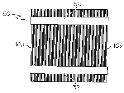
Figs. 3A, 3B and 3C illustrate a package or stack 30 of banded envelopes 10.
The
stack of envelopes 30 includes a plurality of envelopes 10 that are generally
aligned (i.e. their
outer edges are generally aligned). The stack of envelopes 30 includes pair of
bands 32
extending around the outer periphery of the stack 30. The bands 32 may be
located on the
outer longitudinal edges of each envelope 10 and each band 32 may be spaced
apart from the
associated adjacent lateral edge by the same distance. The bands 32 may extend
only around
the longitudinal edges of the inner envelopes 10 (as well as the front and
rear surfaces of the
end envelopes 10a, 10b, respectively) such that all of the imier envelopes in
the stack 30
include two free (unbound) lateral edges.
Fig. 3B illustrates the envelopes 10 in a "flaps-up " configuration wherein
the top flap
16 is located adjacent to, or forms, the upper edge of the envelope 10.
However, if desired the
envelopes can be located in a "flaps-down" configuration wherein the envelopes
10 are
inverted from their configuration shown in Fig. 3B.
The bands 32 can be made of a wide variety of materials, including, but not
limited to,
paper, coated paper, plastic, cardboard, ribbon material, wire, rubber bands
or other elastic
material, non-elastic or generally non-elastic materials, MYLAR film sold by
E.I. DuPont de
Nemours and Company of Wilmington, Delaware, or any combination of these
materials. The
bands 32 may be made of a relatively thin, flexible continuous material, such
as material
having a thickness between about 0.05 mm and about 0.5 mm.
The bands 32 retain the stack of envelopes 30 in a compressed condition. The
stack of
envelopes 30 may be compressed such that the stack 30 exerts an expansion
force of at least
about %a pound, or at least about two pounds, or at least about five pounds,
or at least about ten
pounds. Thus, the bands 32 should be able to withstand an expansion force
applied by the
stack of envelopes 30 of at least about 1/2 pound, or at least about two
pounds, or at least about
five pounds, or at least about ten pounds. In addition, each stack of
envelopes 30 should be
sufficiently compressed to generally seal air and moisture out away from the
innermost
envelopes 10 in the stack 30. For example, the stack of envelopes 30 may be
compressed at
least about 1 inch, or about 10%, or at least about 20%, or at least about
30%, or at least about
CA 02579730 2007-03-07
WO 2006/031755 PCT/US2005/032459
50% from its uncompressed state (i.e., a state wherein each of the envelopes
30 touches any
adjacent envelopes 10 but no external compressive forces are applied).
Although greater compression may, in general, provide greater sealing between
adjacent envelopes 10 and thereby keep air and moisture away from the
envelopes 10, over-
compression of the envelopes 10 can lead to excessive bowing in the stack. In
particular, the
center portions 15 of each envelope 10 have a four-ply or five-ply thickness
due to the
overlapping nature of the five panels 12, 14, 16, 18 at that location. The
remaining portions of
the envelope 10 include only two-ply or three-ply thicknesses. Accordingly, if
the bands 32
are too tight and the envelopes 10 are over-compressed, the outer edges of the
envelopes 10
will be pulled inwardly and the entire stack of envelopes 30 will bow about
the center portion
15 of the envelopes 10. This bowing can impart an undesired curvature to the
envelopes 10
and therefore should be limited. Thus the stack of envelopes 30 should form a
generally
rectangular prism. For example, the stack of envelopes 30 may be configured
such that each
envelope 10 in the stack is bowed (i.e., pulled out of plane) by a distance of
no greater than
about 3/8", or no greater than about one quarter inch, or no greater than
about one-fortieth of
the length of the envelope 10.
Besides the compression advantages provided by the bands 32, the bands 32 also
provide advantages with respect to packaging and/or handling of the envelopes
10. For
example, each band 32 may provide a flat surface upon which suction cups or
other suction
devices may be able to act to thereby grip, lift and manipulate the stack of
envelopes 30. Thus,
each band 32 may have a width of at least, for example, about 1/4", or about
one inch, or at least
about one-tenth of the length of the envelope 10, to provide sufficient
surface area upon which
suction cups can act. Thus, the bands 32 may be of a generally airtight (or
generally non-air
permeable) material that allows suction cups to seal thereto. Of course,
various other methods
of lifting and moving the envelopes may be utilized.
The bands 32 may be printed with various markings located thereon (see marking
31 of
Figs. 3A and 3B). For example, various marks, indicia, targets, text, bar
codes, coinputer or
human readable information, or the like which can be identified or tracked by
optical
equipment associated with a robot or the like (collectively termed "marking"
or "markings"
herein) may be printed on the bands 32. This markings 31 can be utilized by a
vision-guided
robot in an envelope inserting/stuffing machine. The markings 31 can be a mark
located a
6
CA 02579730 2007-03-07
WO 2006/031755 PCT/US2005/032459
predetermined distance from the ends of the stack 30 (i.e., a predetermined
distance from the
front envelope 10a and/or rear envelope l Ob, or from the sides of the stack
30) so that the
optical equipment can determine the location of the outer edges of the package
30. The bands
32 may also include markings 31 useful to a human operator, for example, an
arrow indicating
the orientation and/or front end of the stack 30 for insertion into envelope
inserting or
processing equipment.
Each package 30 may include any of a desired number of envelopes. In one
embodiment each package 30 has between about 50 and about 1,000 envelopes, and
in one
embodiment has about 250 envelopes. Each package of envelopes 30 may have a
depth of
between about 1 inch to about 12 inches, and more particularly about 6 inches.
The banded nature of the envelopes 10 allows the envelopes 10 to be stacked
and
handled in an improved manner as compared to nonbanded envelopes. For example,
as shown
in Fig. 4, a stack 42 of packaged, banded envelopes 30 can be created on a
flat surface, in a
box or the like. When the stack 42 shown in Fig. 4 is located in a box or on
the floor, each of
the packages 30, including the topmost package of envelopes 30a can support
themselves as
freestanding units. If the envelopes 10 of the stack 30a were not banded, the
envelopes 10 of
that package 30a would not be able to be freestanding, and would fall forward
and/or
backward and be difficult to contain.
Accordingly the banded nature of the packages 30 allows a user to extract a
limited
number of envelopes 10 for processing by simply gripping and lifting a package
30 off of the
stack 42 of packages 30 shown in Fig. 4 without causing the tumbling of loose
envelopes.
Thus the packages need not be bound on all sides by a container, and quicker
and easier access
to the packages 30 is provided. In addition, handling equipment (such as
lifting slats or arms)
can be inserted between the bands 32 and stack of envelopes 30 to lift, move
and manipulate
the stack of envelopes 30.
Finally, because the packages of envelopes 30 are compression-bound, a pile or
stack
42 of packages 30 as shown in Fig. 4 can be created and stacked relatively
high. In particular,
the compression-bound nature of the envelopes lends stiffness to the packages
30 (i.e., in the
vertical direction) and allows multiple packages 30 to be piled or stacked on
top of each other
in a secure and stable manner. This allows greater stacking efficiency and
reduces freight
costs and warehouse space.
7
CA 02579730 2007-03-07
WO 2006/031755 PCT/US2005/032459
As shown in Fig. 3D, an envelope dispenser 35 may be provided for use with the
envelope packages 30. The envelope dispenser 35 may have a lower support panel
37, an
upstanding back panel 39 oriented generally perpendicular to the support panel
37, and a pair
of opposed, upstanding side panels 41. Each side panel 41 has an opening 43
through which a
user can extend his or her hands to grip and carry the envelope dispenser 35.
As shown in Fig. 3E the envelope dispenser 35 is configured to store a
predetermined
number of envelope packages 30 (four packages 30 in the illustrated
embodiment). In this
manner the envelope dispenser 35 can be utilized to transport multiple
envelope packages 30.
The envelope dispenser 35 may also be configured to dispense envelopes
directly to an
envelope feeder during the manufacturing process. In particular, four (or more
or less)
envelope packages 30 could be located on the envelope dispenser 35. The bands
32 on the
packages could then be cut and removed. An operator could then invert the
dispenser 35 on
top of a conveyer belt to thereby deposit the envelopes in an aligned and
orderly manner for
easy processing. The use of the dispenser 35 in this manner reduces
repetitious movements by
the operator and increases efficiency.
As shown in Fig. 5, rather than providing a pair of straps 32 located adjacent
to the
outer edges of the envelope stack 30, a single strap 32 may be provided and
located, for
example, about the center 15 of the envelopes 10 of the envelope stack 30. The
use of a center
strap 32 may prevent over-compression of the stack of envelopes 30 due to the
increased
thickness at the center portion 15 of the envelopes 10, as discussed above.
However, the
center strap 32 may, in certain cases, not provide sufficient compression of
the envelopes 30
due to the increased thickness at the center of the envelopes 10 which limits
compression.
Thus, the use of straps 32 which are not located at the center of the
envelopes may be desired.
The center strap 32 of Fig. 5 may be used in combination with one or both of
the outer straps
32 of the arrangement of Figs. 3A and 3B. Indeed, any of a variety and number
of
combinations of straps may be utilized without departing from the scope of the
present
invention.
Figs. 7-25 (as well as Fig. 6) illustrate a series of steps which may be
utilized to form
the stack of banded envelopes 30 shown in, for example, Figs. 3A and 3B.
However, it should
be understood that the method illustrated in Figs. 7-25 is illustrative of
only a single manner in
8
CA 02579730 2007-03-07
WO 2006/031755 PCT/US2005/032459
which the banded envelopes 30 may be assembled, and various other assembly
method or
steps may be utilized to assemble or create the banded envelopes 30 of the
present invention.
As shown in Fig. 7, the banded envelopes may be compiled and banded using a
mechanized assembly, apparatus or envelope stacking machine 48. lii the
illustrated
embodiment, the envelope stacking machine 48 includes a set of three co-axial
spiral wheels or
discs or delivery spiders 50 located at the end of a support table or support
surface 52. The
table 52 has a pair of slots 54 formed therein and extending the length of the
table 52. More or
less slots 54 may be provided as desired to match the configuration of the
particular machine
48. Each spiral wheel 50 includes a set of spiral slots 51 extending in a
general circumferential
direction. Each of the spiral slots 51 is shaped to receive an envelope
therein by an envelope
feeding device (not shown) as the spiral wheels 50 rotate about their central
axes.
In order to commence the stacking operation, the spiral wheels 50 are rotated
in the
direction of arrow A as envelopes 10 (one of which is shown in Fig. 8) are fed
into the spiral
slots 51 of the spiral wheels 50. As the spiral wheels 50 pass through the
slots 54 of the
support table 52, the lower edge of each envelope 10 that is held in the
spiral wheels 50
contacts the support table 52, thereby retracting the envelope 10 out of the
spiral slots 51 upon
continued rotation of the spiral wheels 50. In this mamier, as envelopes 10
are fed into the
spiral wheels 50 at the upstream location of the support table 52, the
rotating spiral wheels 50
continuously deposit an upright stack of envelopes 10 on the support table 52.
As the spiral wheels 50 continue to rotate and deposit envelopes 10, a partial
stack of
envelopes 30' is created on the table 52 (Fig. 8). Thus, Fig. 8 illustrates
the spiral wheels 50 as
an envelope delivery mechanism. However, instead of the spiral wheels 50,
various other
methods of depositing the envelopes 10 onto the support table 52 may be
utilized. For
example, a vacuum wheel or other similar devices may be utilized as the
envelope delivery
mechanism to deposit the envelopes 10 on the support table 52.
The envelope stacking machine 48 includes a horizontally-extending backing bar
56
which is coupled to a backing bar support 58. The backing bar 56 engages the
first envelope
10' deposited on the table 52 by the spiral wheels 50 to provide support to
the first envelope
10' (and subsequent envelopes 10 deposited on the table 52). The backing bar
56 is movable
in the downstream direction B (i.e., along the length of the support table 52)
to accommodate
the growing length of the partial stack of envelopes 30'. As will be discussed
in greater detail
9
CA 02579730 2007-03-07
WO 2006/031755 PCT/US2005/032459
below, the backing bar 56 can be retracted (i.e., moved along its central
axis) into the backing
bar support 58, and Fig. 8 illustrates the backing bar 56 in its extended
position.
As the spiral wheels 50 continue to deposit envelopes 10 on the support table
52, the
partial stack 30' continues to grow and the backing bar 56 moves downstream to
accommodate
the growing stack 30'. As can be seen in Fig. 9, eventually a full stack of
envelopes 30a is
created after a predetermined number of envelopes 10 are located on the
support table 52.
As can be seen in Fig. 9, the machine 48 includes an upper set 58 (58a, 58b,
58c) of
generally vertically oriented fingers and a lower set 60 (60a, 60b, 60c, 60d)
of generally
vertically oriented fingers. The upper set of fingers 58 includes an upstream
pair of upper
fingers 58a, a downstream pair of upper fingers 58c, and an intermediate set
of upper fingers
58b. All of the upper fingers 58 are coupled to an upper finger plate 62, and
are configured
and located to fit between the slots 54 of the support table 52.
Similarly, the lower set of fingers 60 includes an upstream pair of lower
fingers 60a, a
downstream pair of lower fingers 60d, and two intermediate pairs of lower
fingers 60b, 60c.
All of the lower fingers 60 are coupled to a lower finger plate 64 and are
configured to fit
between the slots 54 of the support table 52. Both the upper fingers 58 and
lower fingers 60
are movable in a vertical direction. In addition, as will be discussed in
greater detail below,
the lower fingers 60 are movable in the upstream and downstream directions.
In the depiction of Fig. 9, the upper fingers 58 are located in their lower or
extended
position, and the lower fingers 60 are shown in their lower or retracted
position. In this
configuration, the upstream pair of upper fingers 58a engages the first
envelope 10' of the
stack of envelopes 30a. Once the stack of envelopes 30a engages the upstream
pair of upper
fingers 58a, the backing bar 56 can be retracted into the backing bar support
58, as shown in
Fig. 9. The upstream pair of upper fingers 58a provides support to the stack
30a, thereby
allowing retraction of the backing bar 56 without causing collapse of the
stack 30a. Next, as
can be seen in Fig. 10, the backing bar 56 and backing bar support 58 move
upstream to their
home position adjacent to the spiral wheels 50.
As shown in Fig. 11, the backing bar 56 is then moved to its extended
position. In this
manner, the backing bar 56 creates or defines a break between the stack of
envelopes 30a and a
new stack of envelopes 30b which will be created as the spiral wheels 50
continue to rotate
and feed new envelopes 10 onto the table 52. Thus the upper fingers 58, lower
fingers 60 and
CA 02579730 2007-03-07
WO 2006/031755 PCT/US2005/032459
backing bar 56 together form a separating mechanism, although various other
structures and
devices may be utilized as the separating mechanism.
Immediately after the backing bar 56 is moved to its extended position, the
lower set of
fingers 60 is raised from its lower (or retracted) position to its upper (or
extended) position
such that the lower set of fmgers 60 protrude upwardly through the slots 54 of
the support
table 52. At the same time, the upper set of fingers 58 is raised to its upper
(or retracted)
position until the upper set of fingers 58 are pulled out of contact with the
stack of envelopes
30a. Fig. 11 illustrates the upper 58 and lower 60 set of fingers as they are
in the process of
being moved to their upper positions. As can be seen in Fig. 11, the upper 58
and lower 60 set
of fingers are configured such that the intermediate pair of lower fingers 60b
engage the front
envelope 10' of the stack of envelopes 30a at the same time that the upstream
upper pair of
fingers 58a engage the front envelope 10'. This arrangement ensures that the
envelope stack
30a is held in place as the upper 58 and lower 60 sets of fingers are raised.
Fig. 12 illustrates the upper set of fingers 58 in their fully retracted
position, and the
lower set of fingers 60 in their fully extended position. In this state, the
upstream pair of lower
fingers 60a (not visible in Fig. 12) are located adjacent to the backing bar
56 (i.e., located
between the stacks 30a, 30b). The intermediate pair of lower fingers 60b
engages the leading
envelope 10' of the stack of envelopes 30a to retain the stack of envelopes in
place between the
fingers 60a, 60b.
As the spiral wheels 50 continue to rotate and feed envelopes 10 onto the
support table
52, the backing bar 56 and lower set of fingers 60 move downstream together to
accommodate
the newly-created stack of envelopes 30b. Fig. 13 illustrates a new stack of
envelopes 30b
created in this manner, with the backing bar 56 and lower set of fingers 60
moved downstream
to accommodate this newly-created stack 30b. In addition, because the first
created stack of
envelopes 30a is trapped between the upstream lower pair of fingers 60a and
the intermediate
pair of lower fingers 60b, the first stack of envelopes 30a is simultaneously
moved
downstream along the support table 52.
Next, as shown in Fig. 14, the backing bar 56 is retracted inside the backing
bar
support 58 and moved to its home position. Fig. 14 illustrates the backing bar
56 and backing
support 58 en route to the home position.
11
CA 02579730 2007-03-07
WO 2006/031755 PCT/US2005/032459
As shown in Fig. 15, once the backing bar 56 is returned to its home position,
it is
moved to its extended state such that the backing bar 56 defines the break
between the stack of
envelopes 30b and the next stack of envelopes 30c to be created. In addition,
as can be seen in
Fig. 15, the upper set of fmgers 58 is lowered or moved to its extended
position and the lower
sets of fmgers 60 is lowered or moved to its retracted positions. The stack of
envelopes 30a is
thereby held in place between the upstream pair of upper fingers 58a and the
intermediate pair
of upper fingers 58b, and the stack of envelopes 30b is held in place between
the backing bar
56 and the upstream pair of upper fingers 58a. Next, the lower set of fingers
60 is moved
upstream by a distance equal to the width of the stack of envelopes 30a, 30b
(Fig. 16). Thus,
the upper set of fingers 58 essentially act as a place holder while the lower
set of fingers 60 are
re-set.
As shown in Fig. 17, the lower set of fingers 60 are then raised or moved to
their
extended positions while the upper set of fingers 58 are raised or moved to
their retracted
positions. The upstream pair of lower fingers 60a (not shown in Fig. 17) is
located upstream
of the stack of envelopes 30b and adjacent to the backing bar 56, and the
stacks of envelopes
30a, 30b are retained in place between the various sets of lower fingers 60a,
60b, 60c.
Next, as shown in Fig. 18, as the spiral wheels 50 continue to rotate the
backing bar 56
and lower set of fingers 60 move downstream to accommodate the creation of the
stack of
envelopes 30c. This pattern of retraction and movement of the backing bar 56,
lowering the
upper 58 and lower 60 sets of fingers, moving the lower set of fingers 60
upstream, raising the
upper 58 and lower 60 set of fingers, and moving the backing bar 56 and lower
fingers 60
downstream to accommodate the newest stack of envelopes 30d is repeated until
another stack
of envelopes 30d is created as shown in Fig. 19.
The embodiment of Fig. 19 illustrates four stacks of envelopes 30a, 30b, 30c,
30d
located on the support table 52. However, of course, any number of stacks of
envelopes 30
may be created on the support table 52 in the desired manner, with simple
adjustments in the
fingers 58, 60 and table 52 being made to accommodate the varying number of
stacks 30.
The machine 48 may include a robot arm 70 having a pair of left gripping
paddles 72
and a pair of right gripping paddles 74 to form an envelope stack moving
mechanism. The
robot arm 70 is lowered until the left 72 and right 74 pairs of paddles are
located at either side
of the downstream-most envelope stack 30a (Fig. 20). The left 72 and right 74
paddles are
12
CA 02579730 2007-03-07
WO 2006/031755 PCT/US2005/032459
then moved towards each other to compress the stack of envelopes 30a
therebetween. For
example, as shown in Fig. 6, the paddles 72, 74 may compress the stack 30a
from a width Wl
to a width W2. The squeezing motion of the left 72 and right 74 paddles may
apply the desired
compression to the stack of envelopes 30a, and simultaneously allows the robot
arm 70 to grip
the stack of envelopes 30a for movement and subsequent handling. The paddles
72, 74 and
robot arm 70 may be movable or controllable by various air cylinders, motor
and slide
combinations, linear motors and the like as is well known in the art.
Next, as shown in Fig. 21, the stack of envelopes 30a is lifted by the robot
arm 70 and
moved in a direction perpendicular to the movement of the envelopes along the
support table
52. Alternately, the stack of envelopes 30a could be slid along a table
surface, and could also
be moved in a direction parallel to the movement of envelopes along the
support table 52 (not
shown in Fig. 21). The compressed envelope stack 30a is then positioned on or
in a banding
device or bander 76 for application of the bands. For example, as shown in
Fig. 22, the
banding device 76 may include a pair of banding portions 78 having a spool of
banding
material located in an associated banding spool storage compartment 81. The
spool of band
materia182 is fed around the outer perimeter of a banding opening 84 of each
banding portion
78.
As shown in Fig. 23, the banding portions 78 are then moved towards each other
until
the outer edges of the stack of envelopes 30a are located in the banding
opening 84 of each
banding portion 78. The bands of banding material 82 are then tightened down
or wrapped
around the outer edges of the stack of envelopes 30a. The bands 82 are then
cut and adhered
to themselves to form the bands 32 around the stack of envelopes 30a to retain
the envelopes
in the desired state of compression.
Thus, the banding device 76 wraps the bands 32 around the envelope stack 30a,
cuts
the bands 32 to the proper length, grips each end of the band 32 and adheres,
bonds or
otherwise couples the ends of the bands together. The banding device 76
thereby
mechanically or automatically forms the band 32 around the compressed stack,
as opposed to
manual application of the band 32. The banding device 76 may be a Zeta 144-01
bander sold
by Palamides GMBH of Renningen, Germany, or a B40 bander sold by Band-All
Vekamo
V.D. of Holland, or a US-2000 bander sold by Automatic Taping Systems AG of
Zug,
Switzerland, or any of a variety of other banding machines. The band ends 32
can be coupled
13
CA 02579730 2007-03-07
WO 2006/031755 PCT/US2005/032459
together in various manners, such as heat, ultrasonic welding, gluing or
adhesive, or the like.
If the banding materia182 has markings 31 located thereon, the markings may be
printed
during or immediately prior to the banding process. Alternately, the banding
material 82 may
be preprinted with the desired markings.
As indicated above, the left 72 and right 74 paddles may be utilized to
conlpress and
grip the envelope stack 30a. However, if desired, other methods may be
utilized to compress
the envelope stack 30a, for exainple simply compressing the envelope stack 30a
between a set
of plates, or routing the envelope stack 30a between a pair of converging
walls. In addition,
the banding device 76 may be able to compress the stack of envelopes 30a while
applying the
bands 32.
The banding device 76 may not necessarily apply both bands 32 simultaneously.
For
example, a banding device 76 having only a single banding portion 78 may be
utilized, in
which case the stack of envelopes 30a or the banding device 76 can be rotated
to apply a band
32 to both ends of the envelope stack 30a. Of course, if only a single band 32
is applied to the
stack of envelopes 30a (i.e. as shown in the embodiment of Fig. 5) then a
banding device 76
with only a single banding portion 78 need be utilized.
After the bands 32 are securely applied to the envelope stack 30a, the banding
portions
78 of the banding device 76 move away from each other, as shown in Fig. 24,
and the robot
arm 70 lifts the banded stack of envelopes 30a out of and away from the
banding device 76.
The robot arm 70 can then place the banded stack of envelopes 30a in a
shipping container,
storage container, conveyor belt, or other machine or device for further
processing. In the
embodiment shown in Fig. 25, the stack of banded envelopes 30a is located in a
box 80 for
subsequent shipping. The box 80 can be quite large, and may have a footprint
that is about 3' x
3' or about 4' x 4' to provide for a large storage volume. This footprint is
about sixteen times
larger than the boxes 22 of Fig. 2A, and about eight times larger than the
footprint of the boxes
26 of Fig. 2B.
Although not necessarily shown in Figs. 20-25, as the stack of envelopes 30a
is banded
and placed for packaging by the robot arm 70, the support table 52 may
continue to fill with
new stacks of envelopes 30 and the stacks of envelopes 30 on the table 52 can
be moved
downstream for subsequent gripping and banding. The robot arm 70 then lifts
the newly-
created stacks 30 away from the support table 52 for banding. By lifting and
moving the
14
CA 02579730 2007-03-07
WO 2006/031755 PCT/US2005/032459
stacks of envelopes 30 away from the support table 52, a time buffer between
the continuous
flow of envelopes 10/envelope packages 30 on the support table 52 and the
banding process
(which is an intermittent motion) is created. For example, Fig. 6
schematically illustrates the
package formation, compression and banding step. However, if desired, the
banding process
may be an in-line process in which bands are applied to the sets of envelopes
30 as they are fed
onto the support table 52.
In addition, Figs. 7-25 illustrate a system wherein a single robot arm 70
carries the
stacks of envelopes 30 to the banding device 76, and then places the banded
stacks 30 into a
box 80. However, if desired two robot arms may be utilized. In particular, a
first robot ann
may lift the newly-created stacks 30 off of the support table 52, and
transport them to the
banding device 76 where they are banded. The first robot arm may then place
the banded
envelope stacks in a temporary storage location. A second robot arm or other
loading device
may then transport the banded envelope stacks from the temporary storage
location into a box
80 or other storage location. This method of loading and banding (i.e. in two
discreet steps)
provides an addition time buffer and may allow for quicker processing.
Besides placing the banded envelope stacks 30 in the boxes 80, the banded
envelope
stacks 30 may be placed into chipboard containers, corrugated cardboard
containers, plastic
shipping containers or stacking trays. When the banded envelopes 30 are placed
into large,
collapsible/recyclable stacking trays, the stacking trays can then be shipped
to the customers
for use. Once the envelopes 10 are consumed, the stacking trays can be folded
and returned to
the envelope manufacturer for reuse. In this case, the only waste (i.e.,
packaging) product
from the customer's viewpoint is the bands 32 around each envelope stack 30.
This provides a
significant decrease in waste compared to various boxes or other wrapping
materials in which
prior art envelopes may be packaged. If desired, the boxes 80 or other storage
containers may
be located on a wheeled dolly 83 (see Fig. 25). The wheeled dolly 83 allows
the box 80 to be
easily moved about the floor of the manufacturing or assembly plant.
Figs. 26-33 illustrate a series of steps showing one manner in which the
banded
envelope stacks 30 may be processed by a customer of the envelope stacks 30,
such as a
commercial envelope processor, and how the banded stacks 30 can be utilized
with envelope
inserting machinery. As shown in Fig. 26, a forklift or other vehicle 100
carries a container or
tray 102 with a stack of banded envelopes 30 located therein. This tray 102
could have been
CA 02579730 2007-03-07
WO 2006/031755 PCT/US2005/032459
loaded with envelope packages 30 in the manner shown in Figs. 24 and 25, and
then shipped to
the end user who will process/stuff the envelopes. The forklift 100 positions
the container 102
under a robot arm 104. The robot arm 104 is movable into various
configurations, and is
slidable or translatable along an overhead beam 106.
As shown in Fig. 27, once the forklift 100 has loaded the container 102 in the
appropriate location, the forklift 100 is backed away from the container 102
and the robot arm
104. The robot arm 104 is then activated and moved until it is located above
an envelope stack
30' to be lifted. Next, as shown in Fig. 28, the robot arm 104 grips and lifts
the envelope stack
30'. The robot arm 104 may have various gripping/lifting means for gripping
and lifting the
envelope stack 30'. However, in one embodiment, the robot arm 104 includes a
plurality of
vacuum suction cups located thereon (not shown) which engage the band 32 or
bands 32 of the
stack of envelopes 30' to allow the robot arm 104 to grip and lift the stack
of envelopes 30'.
Next, as shown in Fig. 29 the stack of envelopes 30' is positioned above a
conveyor
table 108. The arm 104 then positions the stack of envelopes 30' on the
conveyor table 108
and releases the stack of envelopes 30' at the end of the conveyor table 108,
as shown in Fig.
30. The conveyor table 108 feeds the stack of envelopes 301ocated thereon in a
downstream
direction for processing by the envelope inserting machine 112. Alternately,
the robot arm
104 can place envelope stacks 30 onto a tray (not shown) which can hold
multiple stacks 30
(i.e. 3-5 stacks). This tray can then be transported, via conveyer or chain-
belt systems, to an
inserting machine. The robot arm 104 may then return to the container 102 to
continue
loading envelopes stacks 30 onto the conveyor table 108/tray as desired.
In many envelope inserting machines, an outer or carrier envelope receives an
inner or
return envelope therein. In one embodiment of the present invention, the outer
and inner
envelopes are both packaged in (separate) banded packages. Accordingly, in
Fig. 30 the outer
banded envelopes are shown as envelope stacks 30 and the inner banded
envelopes are shown
as envelope stacks 110 stored within a container or tray 111.
Accordingly, the robot ann 104 may be utilized to lift a banded stack of inner
envelopes 110 (Fig. 31) out of the container 111 and to place the lifted stack
of envelopes 110
on the inner envelope conveyor table 114 (Fig. 32). Next, as shown in Fig. 33,
an operator 120
can lift a stack of envelopes 110 off the end of the inner envelope conveyor
table 114, remove
the bands 32 and place the stack of envelopes 110 in or on the envelope
inserting machine 112
16
CA 02579730 2007-03-07
WO 2006/031755 PCT/US2005/032459
for further processing. The inner envelope conveyor table 114 can then be
activated to move
or index the stacks of inner envelopes 110 downstream to replace the removed
stack of
envelopes 110.
The operator 120 may also move to the downstream end of the envelope conveyor
table
108 and remove envelope stacks 30 therefrom, remove the bands 32 and insert
the envelope
stacks 30 in or on the envelope inserting machinery 112. The envelope conveyor
table 108 can
then be activated to move the stack of envelopes 30 downstream or alternately
the conveyor
tables 108, 114 may move constantly to replenish the removed envelope stacks.
In this
manner, the robot arm 104 can automatically lift stacks of envelopes 30, 110
out of the
associated containers 102, 111 to constantly replenish the stack of envelopes
on the conveyor
tables 108, 114.
The system of Figs. 26-33 may be considered to be semi-automated in that an
operator
removes the bands 32 and actually places the envelopes on or into the envelope
inserting
machine 112. Alternately, the system of Figs. 26-33 may be fully automated and
may not
require the use of an operator 120. In this case the conveyer tables 108, 114
may feed their
envelope stacks directly into the envelope inserting machinery. However in
this scenario the
bands 32 will need to be removed. Thus the bands 32 could be removed by the
robot ann 104,
or by some other mechanism while the envelope stacks 30 are located on the
conveyer tables
108, 114, or by the envelope inserting machine 112. Further alternately, the
envelope inserting
machine 112 may include or be coupled to an envelope input feeding unit. The
envelope input
feeding unit separates and integrates individual envelopes that were
previously banded
together into the envelope inserting machine 112.
If desired, the output of the envelope inserting machine 112 (i.e. the
processed or
inserted envelopes) may also be able to be automatically processed by the
robot arm 104, or by
another robot arm. For example, the robot arm 104 may be able to lift the
stacks of processed
or outputted envelopes and insert the processed envelopes into a shipping or
storage container.
Figs. 34-48 illustrate an automated loading process utilizing a robot arm 104
that is
movable along an overhead beam 106, similar to the system of Figs. 26-33. In
contrast to the
system of Figs. 26-33 (which includes only a single envelope inserting machine
112), the
system of Figs. 34-48 includes four envelope inserting machines 112 (see Fig.
48, although for
illustrative purposes Fig. 48 does not illustrate the bands on the envelope
stacks). Each
17 1
CA 02579730 2007-03-07
WO 2006/031755 PCT/US2005/032459
envelope inserting machine 112 has two conveyor tables that feed envelopes to
be processed
into the envelope inserting machines 112. For example, one of the conveyor
tables 158 may
feed outer envelopes to an envelope inserting machine, and the other conveyor
table 126 may
feed inner envelopes to be inserted into the outer envelopes (of course
various other inserts,
besides the inner envelopes, can be stuffed or inserted into the outer
envelopes). As shown in
Fig. 34, a forklift 100 carries a container 102 full of stacks of envelopes 30
and positions the
container 102 (Fig. 35) adjacent to the support beam 106/robot arm 104.
As shown in Fig. 36, the robot arm 104 then positions itself over the stacks
of
envelopes 30. As shown in Figs. 37, the robot ann 104 then lifts four packages
of envelopes
30. The robot arm 104 includes various suction cup devices (not shown) to lift
any desired
number of envelope packages 30. Accordingly, in the embodiment illustrated in
Fig. 37, the
robot ann 104 includes a relatively high number of suction cups to grip and
lift the four
envelope packages 30.
As shown in Fig. 38, the robot arm 104 deposits one of the envelope packages
30 on a
first envelope conveyor table 126. As shown in Fig. 39, the robot arm 104 then
moves along
the length of the overhead beam 106 towards the second conveyor table 128. The
robot arm
104 then deposits a stack of envelopes 30 on the second conveyor table 128
(Fig. 40). The
robot arm 104 then moves further along the overhead beam 106 until the robot
arm 104 is
positioned above a third conveyor table 130 (Fig. 41). As shown in Fig. 42,
the robot arm 104
then deposits a stack of envelopes 30 onto the third conveyor table 130. As
shown in Fig. 43,
the robot arm 104 then moves further along the overhead beam 106 towards a
fourth conveyor
table 132, and deposits the last held stack of envelopes 30 onto the fourth
conveyor table 132
(Fig. 44).
If desired the robot arm 104 may then move along the overhead beam 106 to
container
150 which includes additional stacks of envelopes 30 located therein. The
stacks of envelopes
30 in the container 150 may be, for example, inner envelopes and stacks of
envelopes in the
container 102 may be, for example, outer envelopes. As shown in Fig. 46, the
robot arm 104
can then lift the desired number of envelope stacks 30 out of the container
150 so that the lifted
envelopes 130 may be placed in the various conveyor tables 152, 154, 156, 158
which receive
and process the inner envelopes. As shown in Fig. 47, an operator 120 may then
lift various
stacks of envelopes 30 off of the conveyor table (i.e., conveyor table 154 in
the illustrated
18
CA 02579730 2007-03-07
WO 2006/031755 PCT/US2005/032459
einbodiment) and load the stack of envelopes 30 into or on the envelope
inserting machinery
112. Of course, the operator 120 can also load stacks of envelopes from any of
the conveyor
tables 126, 128, 130, 132, 152, 154, 156, 158 on or into the associated
envelope inserting
machine 112. In this manner, as shown in Fig. 48, a single robot arm 104, fed
by two
containers 102, 150 can constantly replenish the various conveyor tables 126,
128, 130, 132,
152, 154, 156, 158 and the containers 102, 150 are replenished as needed by
forklift. The
banded nature of the envelopes 30 allows the improved processing and handling
by the robot
arm 104.
The system of Figs. 34-48, as illustrated, is a semi-automated process.
However, as
described above in the context of the system of Figs. 26-33, the system of
Figs. 34-48 may be
fully automated such that the conveyer tables may feed their envelope stacks
directly into the
envelope inserting machinery, the bands can be automatically removed, and the
output of the
envelope inserting machines can be automatically processed.
Figs. 49-64 illustrate a fully automated envelope processing or envelope
inserting
operation in which no human intervention is required during normal operation.
For example,
as shown in Fig. 49 the automated loading process utilizes a robot arm 300
that is movable
along an overhead beam 302, similar to the system of Figs. 26-33 and the
system of Figs. 34-
48. The system of Figs. 34-48 includes four envelope inserting machines 304,
with each
envelope inserting machine 304 having two conveyor tables 306, 306' that feed
envelopes to
be processed into the envelope inserting machines 304 and/or receive an output
(i.e., processed
envelopes) from the envelope inserting machines 304. In particular, each
envelope inserting
machine 304 includes an input conveyor table 306 upon which unprocessed (i.e.,
unstuffed)
envelopes are stored, and an output conveyor table 306' upon which processed
(i.e., stuffed)
envelopes outputted by the envelope inserting machine 304 are stored. However,
if desired
each envelope inserting machine 304 may have two input tables in the manner
described and
shown in Figs. 26-48.
As shown in Fig. 49, a forklift 308 carries a container 310 full of stacks of
banded
stacks of envelopes 312 and positions the container 310 on a conveyer belt 314
located
adjacent to or under the support beam 302/robot arm 300. As shown in Fig. 50,
the forklift
308 may then lift and remove an empty container 316 located at the opposite
end of the
conveyor belt 314. Next, as shown in Fig. 51, the robot arm 300 positions
itself over the
19
CA 02579730 2007-03-07
WO 2006/031755 PCT/US2005/032459
packages of envelopes 320, 322 to be lifted, and lifts the envelope packages
320, 322 out of
the associated container 324. In the embodiment shown in Fig. 51, the robot
arm 300 lifts two
packages of envelopes 320, 322, and may include various suction cup devices to
lift any
number of desired envelope packages. For example, the robot arm 300 may be
able to lift and
manipulate four or more (or less) envelope packages.
As shown in Fig. 52, the bands 328 are then cut away from the envelope package
320,
and drop down into a waste receptacle 330. The bands 328 can be cut or removed
by any of a
variety of methods or means. For example, the robot arm 300 may include
cutting or tearing
means which can cut, rip, tear, sever, shear or otherwise separate the bands
328 from the
associated envelope package 320. Alternately, the robot arm 300 may carry the
gripped
envelope package 320 to a separation mechanism (i.e., a blade, tearing
mechanism, or the like)
which can cut or otherwise remove the bands 328. Further alternately, the
bands 328 may be
removed after the envelope packages 320 are deposited onto a conveyor table
306, for
example, by the envelope inserting machine 304.
Next, as shown in Fig. 53, the envelope package 320 is deposited on a conveyor
table
306 for an envelope inserting macliine 304. Retaining means (not shown) may be
utilized to
keep the now loose stack of envelopes in place. As shown in Fig. 54, the robot
arin 300 may
then move along its overhead beam 302 to another envelope inserting machine
304 to deposit
the remaining envelope package 322 on the envelope conveyor table 306 of that
envelope
inserting machine 304. As shown in Fig. 55, if not already removed, the bands
328 of the
remaining envelope package 322 are removed and, as shown in Fig. 56, the
remaining
envelope package 322 is deposited on the conveyor table 306 of the associated
envelope
inserting machine 304. If the robot arm 300 initially picks up more than two
envelope
packages, the robot arm 300 can then move along its overhead beam 302 to
position the
remaining envelope packages onto the input tables 306 of the other envelope
inserting
machines 304.
If desired, the robot arm 300 may then enter a rest state until further action
is required.
Further action may involve returning to the container 324 to lift additional
packages of banded
envelopes and placing them on the input conveyor tables 306 of the envelope
inserting
machines 304.
CA 02579730 2007-03-07
WO 2006/031755 PCT/US2005/032459
The robot ann 300 may also be utilized to process envelopes on the output
conveyor
table 306' of the envelope inserting machines 304. For example, as shown in
Fig. 57, the robot
arm 300 may position itself above an output conveyor table 306' of one of the
envelope
inserting machines 304. As shown in Fig. 58, the robot arm 300 then lifts two
stacks of
envelopes 332 off of the output table 306' of the envelope inserting machine
304. Because the
envelopes on the output table 306' are not banded, the robot ann 306 may be
required to utilize
means or mechanisms other than suction cups to lift the envelope stacks 332
off of the output
conveyor tables 306'. For example, the robot arm 300 may be able to compress a
number of
envelopes together or scoop a number of envelopes to thereby grip, lift and
manipulate the
envelope stack 332. Once the stacks of loose envelopes 332 are gripped and
lifted (Fig. 58),
the robot arm 300 may then position the gripped envelope stacks 332 over a
shipping or
storage box 334 (Fig. 59). The robot arm 300 may then position the outgoing
envelopes 332
into the storage box 334 and release the envelope stacks 332 therein (Fig.
60).
The lifting and packaging of outgoing, stuffed envelopes may then be carried
out for
other ones of the envelope inserting machines 304, for example loading
envelope stacks 332'
into a box 334' as shown in Fig. 62. In this manner, the robot arm 300 can
ensure that the
input conveyor tables 306 are constantly replenished with stacks of envelopes,
and that the
output conveyor tables 306' are periodically unloaded to accommodate processed
envelopes.
Fig. 63 illustrates the robot arm 300 in its home position wherein the robot
arm 300 is
positioned over the container 324 to grip and lift additional packages of
envelopes for
positioning on the input conveyor tables 306. As shown in Fig. 64, the
conveyor belt 314 may
be activated to move a newly deposited container 310 downstream so that the
newly deposited
container 310 can be moved into position and replace the container currently
being accessed
324 once the container 324 is emptied. Thus, the envelope loading and
unloading process may
be fully automated such that an operator needs only to replace the input
container 324, 310 and
carry away the boxes loaded with inserted envelopes.
In this manner, it can be seen that the banded nature of the envelope
stacks/packages
allows for various improvements in storing, handling, and processing of the
envelopes. Thus
compression bound nature of the envelopes limits warpage. In addition, the
bound stacks
allows a plurality of envelopes to be handled as a unit, rather than on an
individual basis.
Various examples of these improvements are provided herein, although it should
be
21
CA 02579730 2007-03-07
WO 2006/031755 PCT/US2005/032459
understood that the envelope packages can provide various other advantages in
storing,
handling, processing or otherwise which are not explicitly mentioned.
Having described the invention in detail and by reference to the preferred
embodiments, it will be apparent that modifications and variations thereof are
possible without
departing from the scope of the invention.
What is claimed is:
22