Note: Descriptions are shown in the official language in which they were submitted.
CA 02579821 2007-03-08
WO 2006/034182 PCT/US2005/033459
CAPILLARY ION CHROMATOGRAPHY
BACKGROUND OF THE INVENTION
loooil Ion chromatography (IC) has become a widely used analytical
technique for the determination of anionic and cationic analytes in various
sample matrices since it was introduced in 1975. Ion chromatography today
is performed in a number of separation and detection modes. Ion
chromatography with suppressed conductivity detection is the most widely
practiced form of the technique. In suppressed conductivity detection, an
eluent suppression device, termed a suppressor, converts the eluent into a
weakly conducting form and enhances the conductance of target analytes.
The original suppressors were columns packed with ion-exchange resins in
appropriate ionic forms. Those packed-bed suppressors had a relatively
large dead volume and required off-line chemical regeneration. To overcome
this problem, suppressors based on ion-exchange fibers and other
membranes were developed. These suppressors can be continuously
regenerated using either acid or base regenerant solutions.
[ooo2] One disadvantage associated with the original membrane suppressors
was that an external source of either acid or base regenerant solution
typically was used to generate the suppressor continuously. Over the years,
various designs of electrolytically-regenerated membrane suppressors as
described in U. S. Patent Numbers 4,999,098, 5,248,426, 5,352,360, and
6,325,976 have been developed to overcome the limitations associated with
the chemically-regenerated membrane suppressors. The electrolytic
suppressors offer several advantages in ion chromatography. They provide
continuous and simultaneous suppression of eluents, regeneration of the
suppression medium, and sufficient suppression capacity for common IC
applications. They are easy to operate because the suppressed eluent or
CA 02579821 2007-03-08
WO 2006/034182 PCT/US2005/033459
-2-
water can be used to create regenerant ions electrolytically. Thus, there is
no need to prepare regenerant solutions off-Iine. Also, the suppressors are
compatible with gradient separations. They have very low suppression zone
volume, which makes it possible to achieve separations with high
chromatographic efficiency.
[00031 In ion chromatography, dilute solutions of acids, bases, or salts are
commonly used as chromatographic eluents. Traditionally, these eluents are
prepared off-line by dilution with reagent-grade chemicals. Off-line
preparation of chromatographic eluents can be tedious and prone to operator
errors, and often introduces contaminants. For example, dilute NaOH
solutions, widely used as eluents in the ion chromatographic separation of
anions, are easily contaminated by carbonate. The preparation of carbonate-
free NaOH eluents is difficult because carbonate can be introduced as an
impurity from the reagents or by adsorptiori of carbon dioxide from air. The
presence of carbonate in NaOH eluents can compromise the performance of
an ion chromatographic method, and can cause an undesirable
chromatographic baseline drift during the hydroxide gradient and even
irreproducible retention times of target analytes. In recent years, several
approaches that utilize the electrolysis of water and charge-selective
electromigration of ions through ion-exchange media have been investigated
by researchers to purify or generate high-purity ion chromatographic eluents.
U.S. Patent Numbers 6,036,921, 6,225,129, 6,316,271, 6,316,270,
6,315,954, and 6,682,701 describe electrolytic devices that can be used to
generate high purity acid and base solutions by using water as the carrier.
Using these devices, high purity, contaminant-free acid or base solutions are
automatically generated on-line for use as eluents in chromatographic
separations. These devices simplify gradient separations that can'now be
performed using electrical current gradients with minimal delay instead of
using a conventional mechanical gradient pump.
[00041 The combined use of the electrolytic eluent generator and suppressor
has significantly changed the routine operation of ion chromatographic
methods and permits the performance various ion chromatographic
CA 02579821 2007-03-08
WO 2006/034182 PCT/US2005/033459
-3-
separations using only deionized water as the mobile phase. The use of
these electrolytic devices results in significant improvements in the
performance of ion chromatography methods by allowing minimal baseline
shifts during the gradients, greater retention time reproducibility, lower
detection backgrounds, and lower detection limits for target analytes.
looos] Recently, capillary high performance liquid chromatography using
separation columns with internal diameters of 1 mm or smaller has gained
increasing popularity as an analytical separation tool because of the
advantages associated with the miniaturization of separation processes. The
typical separation columns in ion chromatography have column internal
diameters ranging 2 mm to 4 mm,and are operated in flow rate ranging from
0.2 to 3 mL/min. The practice of ion chromatography in the capillary format
(i.e., using small bore columns with internal diameters of about 1 mm or
smaller) potentially has a number of advantages for analysis of ionic
analytes. The use of capillary separation column can improve the
separation efficiency and/or speed. Separation processes in the capillary
format require much smaller amount of sample and thus offer improved
compatibility with applications where amount of sample is limited. Capillary
ion chromatography system typically operates at 1 to 20 pL/min and thus the
amount of eluent consumed is very small. Capillary ion chromatography has
improved capability for continuous operation with minimal intervention and
thus minimizes problems associated with system start-up and shutdown. The
operation of capillary ion chromatography at low flow rates improves the
system compatibility with mass spectrometer. In addition, the practice of ion
chromatography in the capillary format opens the door for the possibilities of
offering new selectivity for difficult applications using new columns packed
with more exotic and difficult-to-make stationary phases.
[00061 When compared to high performance liquid chromatography, ion
chromatography has progressed slower in the area of miniaturization of the
dimension of the separation process. A limited number of studies have been
reported so far in the area of capillary ion chromatography using suppressed
conductivity detection. In 1983, Rokushika and co-workers reported the
CA 02579821 2007-03-08
WO 2006/034182 PCT/US2005/033459
-4-
development of a capillary ion chromatography system using suppressed
conductivity detection (J. Chromatography, 260 (1983) 81-88). In their study,
an anion exchange capillary column was prepared by packing a surface-
agglomerated anion exchange resin in a fused silica capillary with an internal
diameter of 190 pm. The suppressor was fabricated using a Nafion hollow
fiber tubing and was regenerated chemically using an external solution of
0.05 M deodecylbenzenesulfonic acid. Separations of inorganic anions and
carboxylic acids were disclosed. In 1997, Dasgupta and coworker reported
the implementation of a capillary ion chromatography system using an on-line
high pressure electrolytic sodium hydroxide eluent generator (Anal. -Chem.,
29 (1997) 1385-1391). In their system, deionized water was used as the
carrier for electrolytic generation of sodium hydroxide eluents at 2 pL/min
typically, a capillary column packed with anion exchanger was used as the
separation column, and a suppressor prepared using Nafion tubing and
regenerated chemically using a solution of sulfuric acid was used. Both
isocratic and gradient separations of inorganic and organic anions were
disclosed. In 2001, Pyo and Kim reported their work on the development of
capillary ion chromatography using open tubular columns and suppressed
conductivity detection (J. Korean Chem. Soc., 2001, Vol. 45, No. 3). Open
tubular capillary columns coated with DMEOHA latex particles were used as
separation columns. The suppressor was fabricated using a Nafion hollow
fiber tubing and regenerated chemically using an external acid solution.
[00071 In the publications discussed above, capillary ion chromatography with
suppressed conductivity detection was performed using suppressors made of
ion-exchange capillary tubing. These publications disclose chemical
regeneration using an external dilution acid solution. The dead volume of this
type of suppressors can be minimized so that they are compatible with the
capillary separation columns. However, these publications disclosed the use
of chemical regenerant, adding costs of dispensing and disposing of the
chemical regenerant, resulting in potential leakage of the chemical
regenerant across the ion-exchange membrane into the eluent, which raises
the conductivity detection background and affects negatively the sensitivity
of
CA 02579821 2007-03-08
WO 2006/034182 PCT/US2005/033459
-5-
some analytes. There is a need for a capillary ion chromatography system
with an easy-to use, rugged, and reliable capillary suppressor.
SUMMARY OF THE INVENTION
[00081 One embodiment of the present invention is an apparatus for capillary
ion chromatography comprising a suppressor comprising flow-through ion
exchange packing in a hdusing including a packing inlet and a packing outlet,
and capillary tubing having an inlet and an outlet and formed of a
permselective ion exchange membrane, said tubing being at least partially
disposed in said ion exchange packing.
looov] Another embodiment of the invention is an apparatus for capillary ion
chromatography comprising (a) a suppressor-comprising capillary tubing
having an inlet and an outlet and formed of a permselective ion exchange
membrane, said tubing being at least partially disposed in a flow-through
housing, (b) a flow-through detector in fluid communication with said
capillary
tube, and (c) a recycle conduit for directing recycled aqueous sample liquid
from-said detector through said flow-through housing to the outside of said
tubing.
[ooiol Another embodiment of the invention is a suppressor comprising
capillary tubing having an inlet and an outlet and formed of a permselective
ion exchange membrane, said tubing being at least partially disposed in a
flow-through housing, in which the outer wall of said capillary tubing
comprises exchangeable ions comprising weakly acidic or weakly basic
functional groups.
looiii A further embodiment of the invention is a method for capillary ion
chromatography including the steps of (a) flowing an aqueous sample stream
including separated sample ionic species of one charge, positive or negative,
in an eluent, through capillary tubing formed of a permselective ion exchange
membrane, said tubing being packed in flow-through ion exchange packing,
and transporting counterions in said eluent of opposite charge to said sample
CA 02579821 2007-03-08
WO 2006/034182 PCT/US2005/033459
-6-
ionic species across said tubing from the inner wall to the outer wall
thereof,
and (b) flowing an aqueous regenerant liquid through said ion exchange
packing past the outside of said tubing to carry away the transported
counterions transported to said outer tubing wall.
100121 A further embodiment of the invention is a method for capillary ion
chromatography including the steps of (a) flowing an aqueous sample stream
including separated sample ionic species of one charge, positive or negative,
in an eluent, through,capillary tubing formed of a permselective ion exchange
membrane, and transporting counterions in said eluent of opposite charge to
said sample ionic species across said tubing from the inner wall to the outer
wall thereof, (b) detecting said separa%d ionic species exiting said capillary
tubing by flowing the liquid sample stream through a detector, and (c)
recycling said aqueous sample stream from said detector to said outer tubing
wall to carry away said counterions transported to the same.
BRIEF DESCRIPTION OF THE DRAWINGS
fooi3l FIGS. 1-5 are schematic representations of different embodiments of
the present invention.
[00141 FIGS. 6-12 are charts of different experimental results illustrating
the
methods and apparatus of the present invention.
DETAILED DESCRIPTION OF THE PREFERRED EMBODIMENTS
looi5l The system of the present invention is useful for determining a large
number of ionic species. The species to be determined are solely anions or
solely cations. Suitable samples include surface waters, and other liquids
such as industrial chemical waste, body fluids, beverages, and drinking
water. When the term "ionic species" is used, it includes species in ionic
form and components of molecules which are ionized under the conditions of
the present invention.
CA 02579821 2007-03-08
WO 2006/034182 PCT/US2005/033459
-7-
[00161 In general, the present invention relates to ion chromatography
apparatus and method in which the chromatography is performed on a
capillary scale. Ion bhromatography systems of the present invention include
(a) a capillary separation column, typically in the form of a chromatography
column, (b) a suppressor in which the effluent from the chromatography
column flows through a capillary-sized tubing in the suppressor ("a capillary
suppressor"), and (c) a detector, typically a conductivity detector,
downstream of the suppressor
[00171 The term "capillary tubing" is defined to encompass narrow bore
capillary tubing as-generally used in chemical analysis but is not limited to
such capillary tubing. Instead, the term "capillary tubing" broadly includes
tubing having the dimensions on the order of magnitude of the internal
dimensions of prior art capillary tubing. Such capillaries typically have a
bore
diameter ranging from about 5 to 1,000 microns, more preferably from about
to 500 microns. Such dimensions typically apply both to the separator
column and the suppressor capillary tubing of the present invention. One or
more segments of capillary tubes may be joined to form continuous capillary
tubing. The capillary tubing leads to capillary flow rates, e.g. 0.1 to 50
pL/min.
[00181 In general, any of the well-known ion chromatography systems, e.g.,
as illustrated in U.S. Patent Nos. 3,897,213, 3,920,397, 3,925,019 and
3,956,559 may also be employed but using the capillary suppressors of the
present invention.
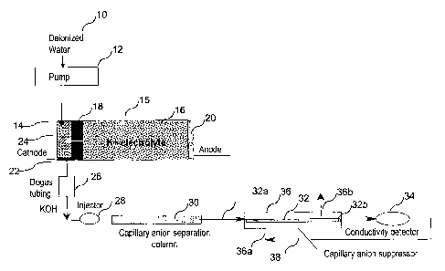
[ooi9l In one embodiment of the invention, illustrated in FIG. 1, the
capillary
suppressor of the present invention is illustrated schematically. In this
embodiment, an eluent generator of the type illustrated in FIG. 1 of U.S.
Patent No. 6,682,701 is used, although other eluent generators as illustrated
in that patent or elsewhere can be used in combination with the capillary ion
chromatography system of the present invention. The principles of operation
of the eluent generator are fully illustrated in this patent. Also, the system
of
FIG. 1 illustrates a recycle of solution from the detector to the outside of
the
CA 02579821 2007-03-08
WO 2006/034182 PCT/US2005/033459
-8-
capillary tubing as will be described more fully hereinafter. Such recycle for
different forms of suppressors is illustrated in U.S. Patent No. 5,248,426.
foo2ol Referring specifically to the embodiment of FIG. 1, deionized water
from a source, not shown, is pumped by pump 12 through high pressure base
generator chamber 14 of base generator 15. Chamber 14 is separated from
a low pressure ion source reservoir 16 including a source of eluent ion. As
illustrated, the system is for anion analysis in which the ions to be supplied
for the analyte are cations, potassium ion as illustrated, or sodium, lithium
or
other cations. The ion source reservoir may be in the form of a base or salt
solution which can be replenished as illustrated in the '701 patent. A
charged permselective membrane barrier or connector 18 substantially
prevents bulk liquid flow while providing an ion transport bridge to transport
the potassium ions into the base generation chamber 14. Suitable
membranes, e.g. ones formed of Nafion , are illustrated in the '701 patent.
An anode 20, e.g. platinum, is in electrical communication with reservoir 16
and a cathode 22, e;g. platinum, is disposed at the outlet of base generation
chamber 14. Cation exchange packing such as a resin bed may be disposed
in base generation chamber 12 as illustrated in the '701 patent. Electrolysis
is performed to provide the reaction illustrated in the '701 patent so that
the
base, KOH, is generated in base generation chamber 14. Under the applied
electric field, the potassium ions migrate across the ion exchange connector
or membrane to combine with hydroxide ions to form a KOH eluent. The
concentration of KOH solution formed is proportional to the applied current
and inversely proportional to the flow rate of the deionized water carrier
stream. Hydrogen is generated at the cathode which could interfere with
analysis. Thus, it is preferable to use a degassing tubing device 26 typically
using a porous membrane to remove generated hydrogen gases, also
illustrated in the '701 patent.
[ooail Sample is injected in injector 28 and is carried by the eluent from
base
generator 15 to ion exchange chromatographic separation column 30. For
anion analysis, separation is performed using anion separation medium,
CA 02579821 2007-03-08
WO 2006/034182 PCT/US2005/033459
-9-
typically a packed bed of ion exchange resin in column 30, but of a capillary
dimension, as set forth above.
[ooazj As illustrated, the effluent from capillary anion separation column 30
flows to the inlet 32a of capillary tubing 32, then through the tubing and out
outlet 32b and through detector 34, suitably a conductivity detector. Tubing
32 is contained within a suppressor housing 36 which can be any shape
including tubular or rectangular. The effluent from the detector 34 is
recycled
in line 38 to an inlet port 366 of housing 36 and flows outside tubing 32
preferably countercurrently to the flow in tubing 32, and exits outlet port
36b.
100231 Capillary tubing 32 is formed of a permselective ion exchange
membrane, suitably of the type described in the prior art, such as formed of
Nafion , to block bulk liquid flow but permit transport of the selected ion,
cation in the instance of anion analysis. Thus,.the wall of the tubing serves
the same purposes as a prior art membrane suppressor or a membrane
barrier 18 which can also be formed of Nafion . The details of the
suppressor will be described below.
[00241 Other eluent generators may be used with an ionized water source,
such as a generator for a carbonate salt such as potassium carbonate
illustrated in PCT Application WO/2004/024302. In this instance, the ion
chromatography system downstream from the eluent generator also is as
illustrated in FIG. 1. Other eluent generators can be used, e.g. as
illustrated
in U.S. Patent No. 5,045,204 or U.S. Patent No. 6,562,628.
[oo251 Although the eluent generators are illustrated for anion analysis and
the generation of cations such as potassium ions, for cation analysis, the
same system may be used for generating MSA or other anions for an eluent
by appropriate reversal of the polarity of the membrane ion exchange resin
and electrodes such as illustrated in U.S. Patent No. 6,682,701.
[00261 It is apparent that the system of FIG. 1 including eluent generation as
illustrated above is capable of performing the entire ion chromatography
CA 02579821 2007-03-08
WO 2006/034182 PCT/US2005/033459
-10-
separation process including analyte separation, eluent suppression, and
analyte detection using one or more flowing streams of deionized water.
10027j FIG. 2 schematically illustrates an embodiment of a capillary
suppressor according to the present invention. Like parts will be designated
below with like numbers for FIGS: 1 and 2. As illustrated, suppressor
housing 36, suitably formed of a non-conductive, e.g. plastic, column with
flow-through ports, include capillary tubing 32 with an inlet 32a and outlet
32b. The tubing typically projects through liquid tight fittings into and out
of
housing 36 and project in direct or indirect fluid communication with the
outlet
of separation column 30. Outlet 32b of tubing 32 projects through the
housing and is connected to tubing for fluid communication with the inlet of
flow-through detector 34.
loo28] For anion analysis, a cation exchange capillary tubing is preferably
tightly embedded in cation exchange packing 40, suitably a cation exchange
resin.bed in direct contact therewith. Packing 40 is contained in a housing
36. As illustrated, separate fluid connections are used for the stream flowing
through the capillary tubing. A source of flowing aqueous regenerant liquid
flows through packing 40 from inlet 42 in a conduit and through outlet 44
through appropriate fittings. The solution then flows through a conduit to
detector 34. In the embodiment of FIG. 1, the water source for inlet 42 is the
sample stream effluent from the conductivity detector after detection as
illustrated in FIG. 1 which flows in recycle conduit 38 illustrated in FIG. 1.
too29] In one embodiment, cation exchange capillary tubing 32 is made of a
Nafion membrane material or some other form of strongly acidic cation
exchange membrane. A typical length of the capillary tubing within the
suppressor is about 0.1 to 50 cm, preferably 1 to 20 cm. Preferable internal
diameters are between about 0.001 inch to 0.010 inch. In one embodiment,
the cation exchange resin for ion separation is preferably a strongly acidic
cation exchange resin such as sulfonated resin in the hydronium ion (H+)
form.
CA 02579821 2007-03-08
WO 2006/034182 PCT/US2005/033459
-11-
[003ol As used herein, the terms "strongly acidic cation" exchange resin or
functional groups as those terms are used in the field of chromatography.
Thus, for example, Dowex 50W X8 and Amberlite IR 122 are commonly used
strongly acidic cation exchange resins. In this type of resin, the functional
groups are typically strong acids with pKa less than 1. Typical strongly
acidic
functional groups include sulfonic groups.
[0031[ As used herein, the terms "weakly acidic cation" exchange resin or
functional groups as those terms are used in the field of chromatography.
Thus, for example, Chelex-100 and Bio-Rex 70, and Amberlite IRC-76 resins
are commonly used weakly acidic cation exchange resins. In this type of
resin, the functional groups are typically weak acids with pKa greater than 1.
Typical weakly acidic functional groups include carboxylic acid,
chlorocarboxylic acid, and phosphonic acid groups.
[00321 Well-known cation exchange packing 40 in the hydronium form may
also be used in this embodiment. Although packing 40 is described in a
preferred form of ion exchange resin bed, other forms of packing may be
used such as a porous continuous structure with sufficient porosity to permit
flow of solution through without undue pressure drop and with sufficient ion
exchange capacity to form a conducting bridge of cations or anions between
the electrodes. One form of structure is a porous matrix or a sponge-like
material formed of sulfonated, cross-linked polystyrene with a porosity of
about 10 to 15% permitting a flow rate of about 0.1 to 3 mI/min. without
excessive pressure drop.
(00331 In an embodiment not shown, if the flow rate of the sample liquid
stream in recycle conduit 38 is insufficient for its desired effects carrying
away the ions which transport across the wall of tubing 32 and/or for cooling
the suppressor for an electrolytic application, then an additional source of
flowing aqueous liquid, not shown, may be directed through packing 40. In
this instance, the additional source of aqueous liquid may comprise a water
stream, e.g. deionized water, which is pumped to the suppressor and either
combines into a single stream with the water in the recycle conduit or can be
CA 02579821 2007-03-08
WO 2006/034182 PCT/US2005/033459
-12-
directed in a separate conduit through packing 40. As with suppressors
which include the recycle in the prior art, it is preferable to flow the
aqueous
water through the packing external to the tubing countercurrently to flow in
the tubing.
[0034] When the aqueous effluent from the conductivity detector is recycled
and routed through packing 40, the suppressor can be continuously
regenerated as long as there is a continuous flow of water to remove KOH
generated in the hydrolysis of the weakly acidic resin in the potassium form.
Depending on the chemical properties of the functional groups on the resin,
the kinetics of the hydrolysis may become a limiting factor determining the
suppression capacity of device with respect to the influx of KOH eluent into
the suppressor. A second stream of deionized water flowing through the
.resin bed of the suppressor which may be at a flow rate higher than the flow
rate used in the separation process is preferred since it is expected that the
suppression capacity may be improved.
[0035] For anion analysis, a sulfonated membrane capillary tubing is used, as
a base eluent (e.g., KOH) enters the capillary tubing, potassium ions (K+)
exchange with hydronium ions (H+) in the wall of the capillary according to
the following equations:
R-SO3H + KOH (eluent) -+ R SO3K + H20 (suppressed eluent) (1)
R-SO3H + KX (analyte) -~ R SO3K + HX (suppressed analyte). (2)
[0036] In the equation, R represents an ion-exchange surface on the
capillary. Since the cation exchange capillary is in direct physical contact
with the bed of cation exchange resin, K+ ions originally exchanged onto the
wall of the cation exchange capillary continue to exchange with H+ ions on
the resin beads immediately adjacent to the wall. Subsequently, this
exchange process continues to occur among the resin beads that are not in
direct physical contact with the cation exchange capillary and located further
way from the capillary tubing. In this process, cation exchange resin beads
CA 02579821 2007-03-08
WO 2006/034182 PCT/US2005/033459
-13-
become the source of regenerant ions (i.e., H+ ions) to regenerate the cation
exchange capillary tubing. The suppression process continues until the point
when the cation exchange beads surrounding the cation exchange capillary
become predominant in the potassium form and the incoming flux of
hydronium ions to the cation exchange capillary reduce to a level that is
insufficient to neutralize the incoming KOH eluent.
[00371 The effective suppression capacity of the device at a given eluent
concentration and flow rate depends on a number of factors including the
length of the capillary, the eluent flow profile inside the capillary, the
resin
ion exchange capacity, the resin particle size, the amount of the resin
surrounding the capillary, the resin bed geometry and the like. The cation
exchange capillary tubing can be woven into a geometrical pattern to create
torturous flow paths for the eluent going through the capillary to increase
the
contact of the eluent with the wall of the capillary in order to increase the
suppression capacity of the device. The internal opening of the cation
exchange capillary may also be filled with an inert or cation exchange
monofilament to decrease the dead volume of the capillary suppressor as
well as to increase the contact of the eluent with the wall of the capillary
in
order to increase the suppression capacity of the device. Once the effective
suppression capacity of the suppressor is consumed, the resin bed of the
device can be regenerated off-line using an external source of acid to convert
the entire resin bed back to the hydronium form. The constant water flow
may facilitate the potassium/hydronium exchange among the ion exchange
sites to increase the effective suppression capacity of the device. In the
capillary ion chromatography system shown in Figure 1, the aqueous effluent
from the conductivity detector can be recycled and routed through the resin
bed of the capillary suppressor. Alternatively, a separate stream of
deionized water may be directed through the resin bed of the suppressor to
serve the same function.
[00381 As illustrated in FIG. 2, capillary tubing 32 is coiled to flow in a
serpentine path. Depending on the desired length of suppressor capillary
tubing to accomplish suppression, the tubing may be in a straight line or
CA 02579821 2007-03-08
WO 2006/034182 PCT/US2005/033459
-14-
coiled or in any desired configuration. It would not typically be in the
illustrated form with right angle turns because of the resistance to flow.
[0039] In another embodiment, the suppressor of FIG. 2 may be employed
except that the cation exchange resin packing 40 surround the capillary
tubing 32 contains weakly acidic functional groups in addition to strongly
acid
functional groups. The H+ ions associated with the cation exchange resin
particles surrounding capillary 32 act as the source of regenerant ions (i.e.,
H+ ions) and support the suppression process. K+ ions originally exchanged
onto the wall of the capillary continue to exchange with H+ ions on the ionic
exchange resin beads immediately adjacent to the wall. This exchange
process continues to occur in the resin beads not in direct physical contact
with the wall of tubing 32 located further away from the wall. At the same
time, the weakly acidic resin in potassium form can undergo the hydrolysis
reaction according to the follbwing equation:
R-CO3K + H20 -~ R-CO3H + KOH (3)
[00401 When there is a constant flow of water going through the resin bed,
KOH formed in the resin hydrolysis reaction can be routed out of the resin
bed. The regenerated resin then becomes available again for the
suppression process according to the following equation:
R-CO3H + KOH -> R-CO3K + H20 (4)
[0041] The effective suppression capacity of the device at a given eluent
concentration and flow rate depends on a number of factors including length
of the capillary, the eluent flow profile inside the capillary, the resin ion
exchange capacity, the resin particle size, the amount of the resin
surrounding the capillary, the resin bed geometry, etc. In this embodiment,
the resin bed may also consist of a- mixture of both strongly acid cation
exchange resin and weakly acidic cation exchange resin. This can be done
in a uniform or non-uniform mixture of the two different types of resin. In
this
CA 02579821 2007-03-08
WO 2006/034182 PCT/US2005/033459
-15-
resin mixture, the weakly acidic cation exchange resin can be regenerated
continuously through hydrolysis as described above. This offers the
advantage of continuous operation without the need of off-line regeneration
with an external acid solution.
[00421 Another embodiment of capillary tubing 32 for use in the suppressor of
the present ion invention for anion analysis is depicted in schematic FIG. 3.
In this embodiment, the cation exchange capillary contains both strongly
acidic and weakly acidic functional groups. FIG. 3 schematically illustrates a
cross-section of the cation exchange capillary used in this embodiment. The
inner wall of the cation exchange capillary is largely made of ion exchange
material containing strongly acidic functional group. The outer wall of the
capillary includes weakly acidic functional groups (e.g., bound to the
capillary
by grafting to the strongly acidic capillary tubing with linear polymers that
include such groups. Techniques suitable for the modification of the capillary
polymer surface by graft polymerization of a monomer of monomers from
active sites generated on solid polymer surfaces are well known (See, e.g.,
Encyclopedia of Polymer Science and Engineering, Supplement Vol, 2a
edition, John Wiley & Sons (1989) 678, Macromolecules, Vol. 9, (1976), 754,
and Macromolecules, Vol. 12, (1979), 1222). The most common technique is
y-radiation using radiation sources such as 60Co source, which generates
surface radicals, but thermal, photochemical, plasma, and wet chemical
methods can also be used to introduce free radical sites for initiation.
Monomers can be present in the gas phase, in solution, or as neat liquids.
The surface graft polymerization techniques can be used to modify the ion
exchange capillary to include weakly acidic function groups on the outer wall
of the capillary.
100431 As the KOH eluent enters into the capillary tubing, potassium ions (K+)
exchange with hydronium ions (H+) in on the inner wall of the capillary.
Subsequently, K+ ions originally exchanged onto the inner wall of the'cation
exchange capillary continue to exchange with H+ ions on the weakly acidic
functional group attached to the outer wall of the capillary. As described
CA 02579821 2007-03-08
WO 2006/034182 PCT/US2005/033459
- 16-
previously, the weakly acidic functional groups in potassium form can
undergo the hydrolysis reaction according to the following equation:
R-CO3K + H2O -~ R-CO3H + KOH (5)
[0044] KOH formed in the hydrolysis reaction can be routed outside of the
plastic housing 36 when there is a constant stream of water flowing outside
the cation. exchange capillary 32. In this mode of operation, the suppressor
can be continuously regenerated as long as there is a continuous flow of
water to remove KOH generated. The aqueous effluent from the conductivity
detector 34 can be recycled and routed to flow outside of the cation
exchange capillary. A second stream of deionized water suitably at flow
rates higher than the flow rate used in the separation process may be used
since it is expected that the suppression capacity may be improved. In this
embodiment, the weakly acidic functional groups attached to the outer wall of
the capillary tubing can be regenerated continuously through electrolysis as
described above. This offers the advantage of continuous operation without
the need for off-line regeneration with an external acid solution.
[00451 FIG. 4 illustrates an embodiment of an electrolytic capillary
suppressor
capable of continuous operation for anion analysis. Like parts for FIGS. 2
and 4 are illustrated with like numbers. In this embodiment, as in the
embodiment of FIG. 2, the capillary anion suppressor includes a cation
exchange capillary tubing 32 embedded tightly inside a bed of cation
exchange resin 40 housed in plastic column housing 32 with flow-through
ports. The inlet of the resin bed is fitted with a flow-through anode 50,
e.g.,
perforated Pt anode, and the outlet of the resin bed is fitted with a flow-
through cathode 52, e.g., a perforated Pt cathode. Both electrodes are
preferably in direct contact with packing 40 of the foregoing type. The cation
exchange capillary tubing may be made of the foregoing materials in the
foregoing dimensions. In the operation of this type of electrolytic capillary
suppressor, the resin bed is continuously regenerated by hydronium ions
generated throGgh the electrolysis of water at the device anode. The.
CA 02579821 2007-03-08
WO 2006/034182 PCT/US2005/033459
-17-
principles and details of one form of continuous electrolytic suppression are
illustrated in U.S. Patent 6,468,804. As in FIG. 1, the water used in
electrolysis can be supplied the aqueous effluent (i.e., the suppressed
eluent) recycled from the conductivity detector. Also, as set forth above, a
separate stream of deionized water may be directed through the resin bed in
place of or supplemental to the recycle stream.
[0046] In another embodiment of the electrolytic capillary suppressor (not
shown), the operation of this suppressor is same as the embodiment shown
in FIG. 4 except that the water used for electrolytic reactions is routed into
the resin bed through a liquid connecting port located near the center of the
packing 40, e.g., in the center bottom of FIG. 4. In this configuration, the
water is splitting into two streams (one stream flowing out the device anode
50 and the other stream going through the device cathode 52) before exiting
the device. One advantage of this embodiment is that the gases (i.e., oxygen
at the anode and hydrogen at the cathode) formed during the electrolytic
reaction are swept out of the device instead of going through the resin bed,
which may lead to improve suppressor performance.
[0047] FIG. 5 illustrates another embodiment of the electrolytic capillary
suppressor for anion analysis. In this embodiment, suppressor 60 includes
three chambers in which the central chamber comprises ion exchange
packing 40 in which capillary tubing 32 is embedded as illustrated above.
Like parts designated with like numbers for FIGS. 1-4 for this part of the
system. As with the device of FIG. 1, the sample-containing eluent from the
chromatographic column flows into inlet 32a of the capillary tubing, and the
liquid that exits capillary tubing 32b flows to the detector. The water source
62 may be recycled from a detector and/or some other source of aqueous
liquid. The principal difference between the embodiments of FIGS. 4 and 5 is
the presence of one or two electrode chambers out of contact with the flow
through packing 40. In this instance, the solution exiting packing 40 flows
into electrode chamber 64 in which anode 52 is disposed. As illustrated,
optional permselective barrier 66 separates packing 40 from electrode
chamber 62. The solution exiting electrode chamber 64 may be recycled in
CA 02579821 2007-03-08
WO 2006/034182 PCT/US2005/033459
-18-
conduit 66 through electrode chamber 68 for cathode 60 which may also be
separated by optional barrier 70 from packing 40. The use of separate
electrode chambers with or without barriers 68 and 70 for suppressing a
packed resin bed is illustrated in the embodiment of FIG. 2 of U.S. Patent No.
6,027,643. The principal difference between these embodiments is the flow
of the sample containing eluent through the resin bed is in contact with it in
the '643 patent rather than through a capillary tubing within a resin bed as
in
the present invention. The general principles of electrolytic operation are
the
same for the embodiments of FIGS. 4 and 5 with the exception of the
isolation of the electrodes from a flow-through the resin bed. It is
preferable
for the aqueous stream to be routed through the packing 40 for being sent to
the anode and cathode chamber for use in the electrolytic reaction. Flow of
water through packing 40 serves to remove heat generated in the operation
of the electrolytic capillary suppressor.
[00481 In the above embodiments of electrolytic capillary ion suppression,
suppressors can be operated continuously or intermittently. For intermittent
operation, once effective suppression capacity is consumed, the resin bed
can be generated electrolytically to remove potassium ions to convert the
packing back to the hydronium form for the next cycle. The frequency of
such intermittent operation would depend on the device dimensions and the
eluent influx.
[0049] To permit continuous operation without the need for off-line
regeneration of packing 40, a total ion exchange capacity of the packing may
be selected to correspond to the amount of capacity necessary for a
particular eluent stream. For example, for electrolytic operation as in FIG.
4,
the total ion exchange capacity of the packing is least 10 times to as high as
10,000 to 100,000 times or more higher than the ion exchange capacity of
the capillary tubing.
[oo5ol By appropriate reversal of the polarity of the packing electrodes and
membranes, the capillary suppressors of the prior art can be used for
suppressing acid eluents for cation analysis.
CA 02579821 2007-03-08
WO 2006/034182 PCT/US2005/033459
-19-
[oo5ij In order to further illustrate the present invention, the following non-
limiting examples are provided.
Example 1. Electrolytic generation of KOH eluents at capillary
chromatography flow rates. -
[0052] This example demonstrates the electrolytic generation of KOH solution
at capillary chromatography flow rates. A modified Dionex P680 pump
(Dionex Corporation, Sunnyvale, CA) was used to deliver a stream of
deionized water at 10 pL/min. Deionized water was first passed through an
ATC-HC column and a CTC-1 column to remove ionic contaminants and then
routed into a KOH eluent generator for generation of KOH solution. The KOH
eluent genei-ator was prepared by modifying a Dionex EGC-KOH cartridge
(P/N 058900). A Keithley Model 220 Programmable Current Source (Keithely
Instruments, Inc., Cleveland, OH) was used to supply the DC current to the
anode and cathode of the KOH eluent generator. A Dionex ED50A
conductivity detector equipped with a modified flow-through conductivity cell
was used to monitor conductance of the KOH solution formed. A Dionex
Chromeleon 6.5 computer workstation was used for instrument control, data
collection, and processing.
100531 FIG. 6 shows an overlay of 8 conductance profiles of KOH eluents
generated electrolytically at 10 pL/min. In this example, the DC current
applied to the eluent generator was varied from 0 mA to 3.21 mA in 0.321-mA
steps to achieve the generation of KOH eluents in concentrations ranging
from 0 mM to 200 mM in 20-mM steps. The results shown in Figure 6
indicate that it is feasible to generate reproducibly KOH solutions over a
wide
range of concentration at capillary flow rates.
Example 2. Use of a resin-phase regenerant capillary anion suppressor
in capillary IC separation of common anions.
(0054] This example demonstrates the use of a resin-phase regenerant
capillary anion suppressor of the type depicted in FIG. 2 in capillary IC
separation of common anions. The capillary IC system used in the
CA 02579821 2007-03-08
WO 2006/034182 PCT/US2005/033459
-20-
experiment was constructed according to the scheme shown in FIG. 1. A
modified Dionex P680 pump (Dionex Corporation, Sunnyvale, CA) was used
to deliver deionized water at 12 pL/min. To generate a KOH eluent,
deionized water was first passed through Dionex ATC-HC and CTC-1
columns to remove ionic contaminants and then routed into a KOH eluent
generator that was prepared by modifying a Dionex EGC-KOH cartridge (P/N
058900). A Keithley Model 220 Programmable Current Source (Keithely
Instruments, Inc., Cleveland, OH) was used to supply the DC current to the
anode and cathode of the KOH eluent generator. The outlet of the KOH
eluent generator was connected to a high-pressure degas unit to remove
hydrogen gas generated during the electrolytic eluent generation process. A
Rheodyne six-port PEEK high-pressure injection valve (Cotati, CA) was used
for injection of samples. The capillary anion separation column was prepared
by packing a proprietary Dionex surface-functionalized anion exchange resin
in a 1/16-inch OD PEEK tubing of 250 mm in length and 380 pm in internal
diameter. A Dionex ED50A conductivity detector equipped with a modified
flow-through conductivity cell was used. A Dionex Chromeleon 6.5 computer
workstation was used for instrument control, data collection, and processing.
100551 In this example, the capillary suppressor was prepared according
the basic scheme illustrated in FIG. 2. A 15-cm length of Nafion cation
exchange capillary tubing (0.004-inch ID x 0.010-inch OD) was embedded
inside a bed of 8% cross-linked and 20-pm sulfonated styrene divinylbenzene
resin beads (Dionex Corporation) that were housed inside a PEEK column (9-
mm ID x 150 mm in length) with two flow-through liquid connecting ports.
Provisions were also made to provide separate fluid connections to the
Nafion cation exchange capillary tubing. The suppressed effluent from the
conductivity cell was routed through the resin bed of the suppressor at 12
iaL/min.
[0056] FIG. 7 shows the separation of seven common anions (fluoride,
chloride, bromide, nitrite, nitrate, sulfate, and phosphate) obtained using
the
system described above. The concentration of KOH eluent was varied from
38 mM to 200 mM. Complete resolution of all seven anions was obtained
CA 02579821 2007-03-08
WO 2006/034182 PCT/US2005/033459
-21-
when the concentration of KOH eluent was 38 mM. Co-elution of anions was
observed at higher KOH concentrations as expected. The results shown in
FIG. 7 indicate that the resin-phase regenerant capillary anion suppressor of
the type depicted in FIG. 2 can be used successfuily to suppress KOH
eleunts of different concentrations in capillary IC separation of common
anions. More significantly, the results shown in FIG. 7 demonstrate that the
capillary IC system depicted in Figure 1 can be used to perform separation of
anions using one flowing stream of deionized water.
Example 3. Operation of a resin-phase regenerant capillary suppressor
in the suppression of KOH eluent for anion analysis.
[00571 This example demonstrates the use of a resin-phase regenerant
capillary anion suppressor of the type depicted in FIG. 2 in capillary IC
separation of common anions. The capillary ion chromatography system
used in this example was same as that used in Example 2, except that a
different resin-phase regenerant capillary anion suppressor was used. In this
example, the capillary suppressor was prepared according the basic scheme
illustrated in FIG. 2. A 15-cm length of Nafion cation exchange capillary
tubing (0.004-inch ID x 0.010-inch OD) was embedded inside a resin bed
housed inside a PEEK column (9-mm ID x 150 mm in length) with two flow-
through liquid connecting ports. Provisions were also made to provide
separate fluid connections to the Nafion cation exchange capillary tubing.
The suppressor resin bed was made. of a resin mixture of 95 %(w/w) of a 8%
cross-linked and 20-pm sulfonated styrene divinylbenzene resin (Dionex
Corporation) and 5% (w/w) of 200-400 mesh Chelex-100 resin (Bio-Rad
Laboratories, Hercules, CA). The Chelex-100 resin is a cation exchanger
with weakly acidic iminodiacetate functional groups. The suppressed effluent
from the conductivity cell was routed through the resin bed of the suppressor
at 12 pL/min.
[oo581 In this example, the separation of seven anions (fluoride, chloride,
bromide, nitrite, nitrate, sulfate, and phosphate) on the same capillary anion
separation column described in Example 2 was performed continuously for
CA 02579821 2007-03-08
WO 2006/034182 PCT/US2005/033459
-22-
more than 400 runs (each run = 20 min) to monitor the longer-term
performance of the capillary suppressor. 100 mM KOH,was used as the
eluent. As shown in FIG. 8, the suppressor provided stable suppressed
background for at least 380 runs. A slightly unstable suppressed background
was observed for Run #390. A noticeably unstable suppressed background
was observed for Run #400. The results shown in FIG. 8 suggest that the
resin-phase regenerant capillary anion suppressor of the type depicted in
Figure 2 can functions satisfactorily for an extended period of time in
capillary IC separation of common anions. In addition, the results shown in
FIG. 8 demonstrate again that the capillary IC system depicted in Figure 1
can be used to perform separation of anions using one flowing stream of
deionized water.
Example 4. The exchange of cations among sulfonated resin beads in
the hydronium form and sulfonated resin beads in the potassium form.
[oo591 This example illustrates visually the exchange of cations among
sulfonated resin beads in hydronium form and sulfonated resin beads in
potassium form. In this example, a capillary suppressor was prepared
according the basic scheme illustrated in FIG. 2. A 15-cm length of a
proprietary grafted and sulfonated TFE capillary tubing of 0.004-inch ID x
0.010-inch OD (Dionex Corporation) was embedded inside a bed of 200-400
mesh AG 50W X16 resin, a sulfonated cation exchanger available from Bio-
Rad Laboratories (Hercules, CA). The resin bed was housed inside a clear
glass column (6-mm ID x 250 mm in length) available from Bio-Chem Valve,
Inc. (Boonton, New Jersey, USA). Prior to its placement into the glass
column, the 200-400 mesh AG 50W X16 resin was homogenously coated with
a small amount of quinaldine red, a cationic dye. The coated resin has a
golden color when it is in the hydrogen form. The color of the coated resin
changes to magenta when it is in the potassium form. Therefore, the color
change of the resin can be used to visualize the exchange of cations among
sulfonated resin beads in the hydronium form and sulfonated resin beads in
the potassium form. The operation of this capillary suppressor was
evaluated using the system described in Example 2. The suppressor was
CA 02579821 2007-03-08
WO 2006/034182 PCT/US2005/033459
- 23 -
used continuously to suppress 20 mM KOH at 10 pL/min. In this example,
the suppressed eluent from the conductivity cell was routed to waste. A
second stream of deionized water was pumped through the resin bed at 0.25
mL/min.
t00601 A slight color change was observed for the resin surrounding the inlet
end of the sulfonated TFE capillary in the suppressor after 6 hours of
operation. A much noticeable change of resin color was observed for the
resin bed at the inlet end of the suppressor after 72 hours of operation. A
distinct band of resin in the magenta color was observed for the resin bed at
the inlet end of the suppressor after 144 hours of operation. These results
demonstrate visually that K+ ions originally exchanged onto the wall of the
cation exchange capillary continue to exchange with H+ ions on the resin
beads immediately adjacent to the wall, and this exchange process
subsequently continues to occur among the resin beads that are not in direct
physical contact with the cation exchange capillary and located further way
from the capillary tubing.
100611 In another experiment, one drop of quinaidine red coated AG 50W X
16 resin in the potassium form (magenta color) was placed on the bed of
quinaldine red coated AG 50W X 16 resin in the hydronium form (golden
color) in a beaker. After 2 hours, a noticeable decrease in the intensity of
the
magenta color was observed. After about 72 hours, the magenta color of the
added drop of resin further faded away. After 192 hours, the added drop of
resin are hardly distinguishable from the rest of the resin bed, indicating
that
the added drop of resin was converted to the hydronium form.
Example 5. Capillary IC separation of anionic analytes using
electrolytically-generated KOH eluents and suppressed conductivity
detection with electrolytic capillary suppressors of the type depicted in
Figure 5.
[00621 This example demonstrates the use of electrolytic capillary anion
suppressors of the type depicted in FIG. 5 in the capillary IC separation of
common anions. The capillary ion chromatography system used in this
CA 02579821 2007-03-08
WO 2006/034182 PCT/US2005/033459
-24-
example was similar to the one used in Example 2, except that electrolytic
capillary anion suppressors were used. In this example, electrolytic capillary
suppressors were prepared. The capillary anion suppressors consisted of
three PEEK chambers. The eluent chamber contained a cation exchange
capillary tubing embedded tightly inside a bed of cation exchange resin (6 to
8 mm ID x 10 to 25 mm in length). Provisions were made provide separate
fluid connections to the cation exchange capillary tubing in the resin bed.
Either a 15-cm length of a proprietary grafted and sulfonated TFE capillary
tubing of 0.004-inch ID x 0.010-inch OD (Dionex Corporation) or a 15-cm
length of Nafion cation exchange capillary tubing (0.004-inch ID x 0.010-
inch OD) was used in the construction of electrolytic capillary suppressors.
The eluent chamber was physically separated from the cathodic regenerant
chamber and anodic regenerant chamber using a proprietary grafted and
sulfonated TFE cation exchange ion exchange membranes (Dionex
Corporation). The cathode chamber contained a perforated Pt cathode and
the anode chamber contains a perforated Pt anode. Both electrode
chambers had two liquid connecting ports (inlet and outlet). In this example,
the suppressed eluent from the conductivity cell was routed to waste. A
second stream of deionized water was first pumped through the resin bed in
the eluent chamber, then to the anodic regenerant chamber and the cathodic
regenerant chamber at flow rates ranging from 0.1 to 0.25 mL/min. The
Dionex ED50A module was used to supply a DC current of 20 mA to the
electrolytic capillary suppressors. A Dionex EG40 eluent generator control
module was used to supply DC currents to the KOH eluent generation
cartridge for generation of KOH eluents used in the ion chromatographic
separations of anions.
[0063] FIG. 9 shows the suppressed conductivity background obtained using
the system when the concentration of KOH eluent was varied from 20 to 200
mM at 10 iaL/min. The results indicate that the electrolytic capillary
suppressor was capable of suppressing KOH at various concentrations
effectively.
CA 02579821 2007-03-08
WO 2006/034182 PCT/US2005/033459
-25-
[0064] FIG. 10 shows an overlay of 20 corisecutive separations of seven
common anions (fluoride, chloride, bromide, nitrite, nitrate, sulfate, and
phosphate) on a capillary column packed with a proprietary latex-
agglomerated anion exchanger (Dionex Corporation). The separation was
performed using '38 mM KOH at 10 pL/min. The results show highly
reproducible separation of the target anions with analyte retention percent
relative standard deviation (RDS) ranging from 0.028% for sulfate to 0.10%
for phosphate, and analyte peak area percent RSD ranging from 0.033% for
nitrite to 0.58% for phosphate.
[0065] FIG. 11 shows an overlay of 10 consecutive separations of 11
common anions (fluoride, chlorite, bromate, chloride, nitrite, chlorate,
bromide, nitrate, carbonate, sulfate, and phosphate) on a capillary column
packed with a proprietary surface-functionalized anion exchanger (Dionex
Corporation). The separation was performed using KOH eluent with a
concentration gradient from 10 to 45 mM KOH at 10 pL/min. The results
also show highly reproducible separation of the target anions with analyte
retention percent relative standard deviation (RDS) ranging from 0.072% for
phosphate to 0.19% for nitrite.
[0066] The above results demonstrate that the capillary IC system described
in this invention can be used to provide reliable determination of target
anionic analytes using only deionized water as the carrier streams.
Example 6. Capillary IC separation of cationic analytes using
electrolytically-generated MSA eluents and suppressed conductivity
detection with an electrolytic capillary suppressor of the type depicted
in Figure 5.
[0067] This example demonstrates the use of an electrolytic capillary cation
suppressor of the type depicted in FIG. 5 in the capillary IC separation of
common cations. The basic system components of the capillary ion
chromatography system used in this example were similar those depicted in
FIG. I for cation analysis. The methanesulfonic acid (MSA) eluent generator
was prepared by modifying a Dionex EGC-MSA cartridge (P/N 058902). A
CA 02579821 2007-03-08
WO 2006/034182 PCT/US2005/033459
-26-
.
Keithley Model 220 Programmable Current Source (Keithely Instruments,
Inc., Cleveland, OH) was used to supply the DC currents to the MSA eluent
generation cartridge for generation of MSA eluents used in the ion
chromatographic separations of cations.
[00681 The electrolytic capillary suppressor was prepared according the basic
scheme illustrated in FIG.5. The capillary anion suppressors consisted of
three PEEK chambers. The eluent chamber contained a 15-cm length of a
proprietary grafted and aminated TFE capillary tubing of 0.004-inch ID x
0.010-inch OD (Dionex Corporation) embedded tightly inside a strongly basic
anion exchange resin bed (6 mm ID x 20 mm in length). Provisions were
made provide separate fluid connections to the cation exchange capillary
tubing in the resin bed. The eluent chamber was physically separated from
the cathodic regenerant chamber and anodic regenerant chamber using a
proprietary grafted and aminated TFE cation exchange ion exchange
membranes (Dionex Corporation). The cathode chamber contained a
perforated Pt cathode and the anode chamber contains a perforated Pt
anode. Both electrode chambers had two liquid connecting ports (inlet and
outlet). In this example, the suppressed eluent from the conductivity cell was
routed to waste. A second stream of deionized water was first pumped
through the resin bed in the eluent chamber, then to the cathodic regenerant
chamber and the anodic regenerant chamber at flow rates ranging from 0.2
mL/min. The Dionex SC20 suppressor control module was used to supply a
DC current of 15 to 20 mA to the electrolytic capillary suppressor.
[0069] FIG. 12 shows a separation of six common cations (lithium, sodium,
ammonium, potassium, magnesium, and calcium) on a capillary column
packed with a proprietary surface-functionalized cation exchanger (Dionex
Corporation). The separation was performed using 8 mM MSA at 10 pL/min.
An excellent resolution of all cationic analytes was obtained. The results
demonstrate that the capillary IC system described in this invention can be
used to provide separation of target cationic analytes using only deionized
water as the carrier streams.