Note: Descriptions are shown in the official language in which they were submitted.
CA 02580302 2007-03-05
1
PROCESS FOR THE PRODUCTION OF EMBOSSED FILMS BASED ON
PARTIALLY ACETALATED POLYVINYL ALCOHOL
The invention relates to a process for the production of a
film based on partially acetalated polyvinyl alcohol with a
roughness of the surfaces set by two-stage embossing and to
the use of the films for the production of composite glass
laminates.
Composite safety glass panes consisting of two glass panes
and one adhesive film which combines the glass panes and is
based on partially acetalated polyvinyl alcohol, preferably
of polyvinyl butyral (PVB), are used in particular as
windscreens in motor vehicles, it being possible for a
glass pane to be replaced, if necessary, by a polymer pane.
In the construction sector, too, such silicate
glass/silicate glass composites or silicate glass/polymer
composites are used e.g. as window panes or as intermediate
walls, multiple composites, i.e. composites consisting of
more than two supporting layers being used, if necessary
and depending on their application, e.g. as bullet-proof
glass.
STATE OF THE ART
Plasticiser-containing films based on partially acetalated
polyvinyl alcohol, in particular polyvinyl butyral (PVB)
for the manufacture of safety composite glass are soft and
tacky even at room temperature. Although the high tackiness
is essential for holding the composite of glass/film/glass
together in composite glass, the tackiness needs to be
temporarily eliminated or, however, and at least
suppressed, for transportation and the process of
processing them to such glass. The inherent tackiness of
the films can be reduced by a certain roughness.
Moreover, it needs to be possible for the air present
between the film and the glass to be removed during
CA 02580302 2007-03-05
- 2 -
processing of the film to form composite safety glass. In
this respect, it is generally known to provide the films on
one or both sides with a roughened surface. The air
enclosed during the manufacture of the glass laminate is
able to escape via the roughened surface such that a
bubble-free laminate is obtained.
Usually, the roughness values of such an intermediate film,
measured as 1R.z according to DIN EN ISO 4287, are between 8
and 60 pm. A typical process for the manufacture of films
with a roughened surface is known from EP 0 185 863 B1 as
melt fracture process. Melt fracture processes lead to
irregularly (stochastically) roughened surfaces.
Embossing processes are further processes described in the
state of the art for the production of a roughened surface.
The common feature of all film surfaces produced by
embossing processes is a regular (non-stochastic) surface
structure which exhibits a good ventilation behaviour
particularly in the production process for glass laminates
by the vacuum bag process and consequently permits short
process times and wide processing windows.
In comparison with melt fracture processes, embossing
processes have the advantage that the regular surface
structure obtained allows more rapid and simpler air
removal during laminate production.
EP 0 741 640 B1 describes such an embossing process for the
production of a surface embossed on both sides by means of
two embossing rollers by means of which the film is
provided with a regular line structure of the saw tooth
type. The lines embossed on each side of the film cross
each other at an angle of >25 such that a so-called moire
pattern is prevented from forming in the composite glass,
CA 02580302 2007-03-05
- 3 -
EP 1 233 007 Al discloses an embossing process for avoiding
the moire effect which process produces a regular uniform
embossing structure on each side of the film. To avoid
interferences, the line structures of the two film sides
have different repetition frequencies.
Another process which is described in US 5,972,280 uses
only one roller to emboss the surface structure, instead of
two embossing rollers, and a structured steel band fitting
snugly to the roller via rolls and compressed air, the film
being guided during the embossing process through the gap
between the embossing roller and the steel band.
US 4,671,913 discloses a process for embossing PVB films,
the film being embossed in a single operating process
between two structured rollers. The rollers - and
consequently also the embossed film - have a roughness R,
of 10 to 60 Am.
The processes for embossing on both sides described above
have the disadvantage that in the case of single stage
embossing of both sides of the films, only a short
residence time can be achieved in the roller gap. As a
result, the embossing effect decreases strongly with an
increasing embossing speed, which is undesirable for an
industrial production process. Although it is possible to
increase the residence time for one side of the film to be
wound around an embossing roller such that this side of the
film is in contact with the embossing roller longer than
the other side, this reduces the accuracy of embossing
and/or film sides with different embossing depths are
obtained.
In the case of two-stage processes in which both sides of
the film are embossed one after the other, this effect does
not occur. However, in this case there is the risk that the
embossed side of the film is levelled again or over
CA 02580302 2013-01-11
4
embossed in the second embossing step. This can be
suppressed by appropriately selecting the roller surface
and the embossing pressure. Thus, US 2003/0022015, WO
01/72509 and US 6077374 describe a single stage and two-stage embossing
process for PVB films by means of embossing rollers of steel and pressing
rollers
with a rubber coating. The rubber coating and/or the force
applied between the rollers onto the film is not described
in any further detail. If the roller surfaces are too hard,
this leads to a small embossing zone which, in practice, is
reduced to one line. This leads to a lower residence time
of the film in the embossing zone and consequently to a
lower embossing speed. If, on the other hand, roller
surfaces are used which are too soft, only an insufficient
force can be applied onto the film such that the embossing
quality decreases.
The existing processes merit improvement with respect to
the embossing performance.
It was consequently the object of the present invention to
develop a two-stage process for embossing films based on
partially acetalated polyvinyl alcohol, which process does
not exhibit these disadvantages.
Surprisingly enough, it has been found that embossing of a
film based on acetalated polyvinyl alcohol of sufficient
quality and with a sufficient speed between embossing
rollers and pressing rollers of a certain Shore A hardness
is possible.
DESCRIPTION OF THE INVENTION
Method for embossing a foil (also referred to as "a film" hereinafter) based
on
CA 02580302 2013-01-11
partially acetalised polyvinyl alcohol with surface roughnesses of in each
case
independently, Rz = 20 to 100 pm, preferably Rz of 30 to 50 pm comprising the
steps of:
a. preparing a foil based on partially acetalized polyvinyl alcohol with a
surface roughness of Rz = 1 to 70 pm, preferably 1 to 40 pm, in particular 1
to
pm,
b. embossing a first surface of the foil from a) between temperature of 80
to
170 C and pressure roller at a temperature of up to 60 C to obtain a foil with
a
embossed surface roughness of Rz = 20 to 100 pm, and
c. embossing a second surface of the foil from b) between a correspondingly
roughened embossing roller at a temperature of 80 to 170 C and a pressure
roller at a temperature of up to 60 C to obtain a foil with an embossed
surface
roughness of Rz = 20 to 100 pm,
with the pressure rollers of both embossing stages having an identical or
different
Shore A hardness of 50 - 80.
Preferably, the process according to the invention leads to
a non-stochastic roughness of the films. Measuring the
surface roughness of the film with the roughness value Rz
is effected according to DIN EN ISO 4287 and DIN ISO 4288.
The measuring devices used to measure the surface roughness
must satisfy EN ISO 3274. The profile filters used must
correspond to DIN EN ISO 11562.
CA 02580302 2013-01-11
5a
The surface structure and/or roughness of the film
according to step a) may be applied e.g. by the so-called
flow or melt fracture process corresponding to EP 0 185 863
BI. Different roughness levels can be produced by varying the width of the
discharge gap and the temperature of the die lips directly on the die exit.
CA 02580302 2007-03-05
- 6 -
It is also possible to produce films by extrusion without
melt fracture. Alternatively, the film can be produced by
extrusion and smoothing over chilled rollers in line with
US 4,671,913. The use of the films with as low a roughness
as possible is preferred according to the process of the
invention since rough structures can be over-embossed only
with a greater embossing effort. Moreover, the original
roughness may readjust itself during the production of the
pre-composite such that the advantages of an embossed film
compared with a surface roughened by melt fracture are
reduced.
In the subsequent embossing processes according to steps b)
and c), the film is provided on each side, independently in
each case, with a surface structure and a roughness depth
of Rz . 20 to 100 Am, preferably IRõ = 20 to 80 Am, in
particular IR.z = 30 pm to 50 pm.
The process according to the invention can be carried out
in such a way that the sides of the structured film have
different roughness depths R. This can be achieved e.g. by
means of different tools or temperatures of the embossing
tools and/or the pressing rollers.
Before and/or after the embossing processes b) and c), the
film can be cooled to -10 to +20 C to fix the surface
structure of the film in this way. Cooling preferably takes
place via correspondingly temperature-adjusted cooling
rollers. In this case, so-called front cooling is possible,
i.e. the side of the film embossed in process steps b)
and/or c) is cooled. An alternative is so-called back
cooling in the case of which the side of the film not
embossed in process steps b) and/or c) is cooled.
Cooling of the films may also be restricted to their
surface. Thus, the surface temperature of the embossed side
of the film can be adjusted to -10 to +20 C before process
CA 02580302 2013-01-11
7
step c). Alternatively, the non-embossed surface of the
film can be adjusted to this temperature before steps b)
and/or c).
Preferably, the embossing rollers are made of metal and
posses a surface with a negative profile pattern of the
structure present later on in the film surface. The
embossing rollers used according to the process of the
invention must have a roughness corresponding to the
intended roughness of the film. In a process variation, the
embossed film and the embossing rollers have the same or
almost the same roughness. Depending on the process
parameters of film temperature, line pressure, roller
temperature, roller speed or film speed, the roughness of
the embossed film may also be considerably lower than that
of the embossing rollers. Thus, the roughness Rz of the
embossing rollers may be 400%, preferably 300%, in
particular 100% above the roughness R, of the film surfaces
embossed with this roller. The temperature of the embossing
rollers is 80 to 170 C, preferably 100 to 150 C and in
particular 110 to 140 C. Particularly preferably, the
embossing rollers have a coated steel surface (e.g. PTFE)
in order to reduce the adhesion of the film.
In the process according to the invention, the film is
guided between the embossing roller and the pressing roller
rotating in the opposite sense. Preferably, the film is
exposed, between the embossing rollers and the pressing
rollers of process steps b) and/or c) to a line pressure of
CA 02580302 2013-01-11
7a
20 to 80 N/nm, in particular 40 to 65 N/nm. The line pressure can be the same
or
different in process steps b) and c). Line pressure should be understood to
mean
the pressing force of the roller pair based on the film width.
The pressing rollers have temperatures of 0 to 60 C, preferably 10 to 40 C,
i.e.
they are actively cooled vis-à-vis the embossing roller. The temperature of
the
pressing ______________________________________________________________
CA 02580302 2007-03-05
- 8 -
rollers may be the same or different in process steps b)
and c).
The pressing rollers have no or only a slight roughness (R.,
maximum 10 pm) and preferably consist of a metal core with
a surface of rubber or EPDM. The surfaces of the pressing
rollers, in particular, have a Shore A hardness of 60 to
75. The pressing rollers press the film into the structured
surface of the embossing rollers and nestle lightly against
the embossing roller. By changing the line pressure, the
surface of the embossing zone and consequently the
residence time of the film in the roller gap can be
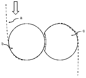
altered. This is illustrated diagrammatically in Fig. 1, a)
indicating the film to be embossed, b) the embossing roller
and c) the pressing roller. Apart from the film being
guided around the rollers, shown here, a simple manner of
guiding the film through the roller gap without passing
around the roller is possible.
By selecting the process parameters of line pressure, film
temperature and/or roller temperature, roller speed and
enveloping angle of the film web on the rollers, the
roughness depth of the film embossing can be influenced
with a given roughness depth of the embossing rollers.
The quality of the embossing process depends also on the
constancy of the temperature of the film and consequently
the chill, pressing and embossing rollers. Preferably, the
temperature difference between the embossing and/or
pressing rollers is consequently adjusted, over their width
and circumference, to less than 2 C, in particular less
than 1 C.
Fig. 2 shows diagrammatically a variation of the process
according to the invention. The direction of travel of the
film is indicated by double arrows. The film (a) which has
been provided with a low roughness is optionally
CA 02580302 2007-03-05
- 9 -
temperature-adjusted in the roller pair (d) and embossed on
one side between the embossing roller (e) and the pressing
roller (f). (e) and (f) are temperature-adjusted as
described. Subsequently, the temperature of the film thus
embossed on one side is adjusted in the roller pair (g).
The second surface of the film is embossed by means of the
again temperature-regulated embossing roller (h) and the
pressing roller (i). The rollers not provided with a
reference in Fig. 2 are used to guide the film. For a
better temperature adjustment, the roller pairs (d) and (g)
can also be surrounded by the film such that the residence
time of the film on the rollers is increased.
Fig. 3 shows a further variation of the process according
to the invention. In this case, the film is (a) embossed,
after optional temperature-adjustment, in roller pair d' on
one side between the embossing roller (e) and the pressing
roller (f) and subsequently temperature-adjusted on one or
both sides in the roller pair (g'). The second side of the
film is subsequently embossed between the embossing roller
(h') and the pressing roller (i'). The surface structure is
fixed by means of the chill rollers (j).
In this case, too, the film can be guided through the
roller gap of the temperature-adjustment rollers directly,
i.e. without passing around them.
It is possible to use in particular polyvinyl butyral
(PVB), in the crosslinked or non-crosslinked form as
partially acetalated polyvinyl alcohol, in mixture with at
least one plasticiser, dyes, pigments, metal salts for
adhesion regulation, organic additives and/or inorganic
fillers.
All plasticisers known in the art for this purpose, in
particular the esters of multivalent acids, polyhydric
alcohols or oligoether glycols, such as e.g. adipic acid
CA 02580302 2007-03-05
- 10 -
esters, sebacic acid esters or phthalic acid esters, in
particular di-n-hexyl adipate, dibutyl sebacate, dioctyl
phthalate, esters of diglycol, triglycol or tetraglycol
with linear or branched aliphatic carboxylic acids and
mixtures of these esters are suitable, on the one hand, as
plasticisers for the partially acetalated polyvinyl
alcohols. Esters of aliphatic diols with long chain
aliphatic carboxylic acids, in particular esters of
triethylene glycol with aliphatic carboxylic acids
containing 6 to 10 C atoms, such as 2-ethyl butyric acid or
n-heptanoic acid are preferably used as standard
plasticisers for partially acetalated polyvinyl alcohols,
in particular polyvinyl butyral. One or several
plasticisers from the group consisting of di-n-hexyl
adipate (DHA), dibutyl sebacate (DBS), dioctyl phthalate
(DOP), esters of diglycol, triglycol or tetraglycol with
linear or branched aliphatic carboxylic acids, in
particular triethylene glycol-bis-2-ethyl butyrate (3GH),
triethylene glycol-bis-n-heptanoate (3G7), triethylene
glycol-bis-2-ethyl hexanoate (3G8), tetraethylene glycol-
bis-n-heptanoate (4G7) are used particularly preferably.
In a particular embodiment of the present invention, the
adhesion of the film to the embossing tools can be further
reduced by adding a substance reducing adhesion to the film
material.
0.01 to 2% by weight, based on the total mixture, of
pentaerythritol with the formula I
R3
RI- C -R2
R4
in which R1, R2, R3, R4 represent identically or
differently radicals of the group of CH2OH, CH2OR5,
CH2OCOR5 or CH2OCO-R6-COOR5, and R5, R6 represent
saturated or unsaturated, branched, or unbranched
CA 02580302 2013-01-11
11
hydrocarbon radicals with 1 to 26 carbon atoms can be
added as organic additives reducing adhesion.
In the case of the use of partially acetalated polyvinyl
alcohols as polymeric materials, the pentaerythritols or
their esters used as an optional additive facilitate also
the use of special plasticisers which, for example, have an
improved sound deadening effect on the films, compare also
DE 199 38 159 Al. The special plasticisers include in particular the group of
plasticisers consisting of
= polyalkylene glycols with the general formula
HO-(R-0)-H with R = alkylene and n > 5,
= block copolymers of ethylene glycol and propylene glycol
with the general formula HO-(CH2-CH2-0)n-(CH2-CH(CH3)-0)m-
H with n > 2, in > 3 and (n+m) < 25,
= derivatives of block copolymers of ethylene glycol and
propylene glycol with the general formula R10-(CH2-CH2-
0)n-(CH2-CH(CH3)-0)m-H and/or HO-(CH2-CH2-0)n-(CH2-CH(CH3)-
0).-12.1 with n>2, m > 3 and (n+m) < 25 and R1 as organic
radical,
= derivatives of polyalkylene glycols with the general
formula R1-0-(R2-0)-H with R2 = alkylene and n > 2, in
which the hydrogen of one of the two terminal hydroxy
groups of the polyalkylene glycol is replaced by an
organic radical R1,
CA 02580302 2013-01-11
ha
= derivatives of polyalkylene glycols with the general
formula R1-0-(R2-0)n-R3 with R2 = alkylene and n > 5, in
which the hydrogen of the two terminal hydroxy groups of
the polyalkylene glycol is replaced by an organic
radical R1 or R3.
In the case of partially acetalated polyvinyl alcohols, in
particular PVB in this case, these special plasticisers are
preferably used in combination with one or several standard
CA 02580302 2007-03-05
- 12 -
plasticisers in a proportion of 0.1 to 15% by weight, based
on the plasticisers.
The plasticised partially acetalated polyvinyl alcohol
resin preferably contains 25 to 45 parts by weight and
pyrticularly preferably 30 to 40 parts by weight of
plasticiser, based on 100 parts by weight of resin.
The partially acetalated polyvinyl alcohols are produced in
the known way by acetalation of hydrolysed polyvinyl
esters. Formaldehyde, acetaldehyde, propionaldehyde,
butyraldehyde and such like, preferably butyraldehyde, for
example, are used as aldehydes.
The preferred polyvinyl butyral resin contains 10 to 25% by
weight, preferably 17 to 23% by weight and particularly
preferably 19 to 21% by weight of vinyl alcohol radicals
and/or 0 to 20% by weight, preferably 0.5 to 2.5% by weight
of acetate radicals.
In a further process variation, a PVB partially crosslinked
with a polyaldehyde (in particular glutaraldehyde) and an
oxocarboxylic acid (in particular glyoxylic acid) is used
as polymer according to NO 2004/063231 Al. Such a partially
crosslinked PVB has a viscosity which is 10 to 50% higher
than that of the analogous non-crosslinked PVB.
The water content of the films is preferably adjusted to
0.15 to 0.8% by weight, in particular to 0.3 to 0.5% by
weight.
The films produced according to the invention can be used
in particular for the manufacture of laminates from one or
several glass panes and/or one or several polymer panes and
at least one structured film.
CA 02580302 2007-03-05
- 13 -
During the manufacture of these laminates, a pre-composite
is first produced from the glass/polymer panes and the film
by pressing, vacuum bag or vacuum lip. As a rule, pre-
composite laminates are slightly turbid as a result of air
inclusions. The final manufacture of the laminate takes
place in the autoclave e.g. according to WO 03/033583.
EXAMPLE:
A plasticizer-containing PVB film of 72.5% by weight PVB,
25% by weight 3G8 with potassium salts and magnesium salts
as anti-adhesion agents with a roughness on both sides of
Rz 5 pm is embossed in a facility according to Fig.3. The
pressing and embossing rollers of the two embossing stages
had identical properties.
Facility parameters:
Embossing roller diameter: 245 mm
Hardness of the rubber roller 70 + 5 Shore A
Diameter of the rubber roller: 255 mm
Roughness of the embossing roller: approximately 80 pm
Surface coating: PTFE
Films with the following embossing properties were
obtained:
No. Line speed Line T of T
of Rz (pm) Rz (pm)
(m/min) pressur embossing rubber upper
under-
roller ( C roller side
side
(N/mm) ( C)
1 1.34 32 100 10 30
32
2 1.42 48 100 10 45
45
3 2.3 50 110 10 40
40
4 2.75 40 110 10 48
38
5 6.0 60 110 10 38
44
CA 02580302 2007-03-05
- 14 -
In order to achieve identical roughnesses on both film
sides it may be necessary to use different parameters in
the two embossing stages, as illustrated in the following
example:
No. Line Line pressure T of T of Rz
(pm) Rz ( m
speed (N/mm) embossing rubber upper
under-
(m/min up.s (und.$) roller ( C) roller side
side
up.s (und.$) ( C)
6 2.3 70 (80) 120 (125) 10 90 90
During the manufacture of the composite glass, the films
exhibited good air removal properties and could be
processed to blister-free laminates.
Comparative example:
Instead of rubber rollers with the Shore A hardness
according to the invention, steel rollers were used.
Even when using two coated embossing rollers, the film
tends to stick to one of the rollers since no defined take-
off point is present. Moreover, the film becomes smooth on
one side at speeds of approx. 3m/min and more since the
residence time in the embossing gap is too short.
No films usable for the manufacture of composite glass were
obtained and such a process is unsuitable for industrial
purposes.