Note: Descriptions are shown in the official language in which they were submitted.
CA 02580699 2007-03-16
EP 05 788 977.6
Semperit AG Holding
Hand rail and guide rail for a passenger conveying
installation
The present invention relates to a hand rail for a passenger
conveying installation such as e.g. an escalator or
passenger conveyor. The invention further relates to a
guide rail for such a hand rail and a side covering of a
passenger conveying installation with a balustrade, a guide
rail fixed thereto and a hand rail guided on the guide rail.
Installations for conveying passengers, whether escalators
or passenger conveyors, are usually provided on each side
with an endless moving hand rail, which is driven
synchronously with the conveying installation carrying the
passengers. The hand rail is guided in a guide rail mounted
on a balustrade. The return belt and the drive for the hand
rail can either be enclosed in the balustrade, or disposed
under or next to the same.
The hand rails used for this purpose are conventionally
composed of a flexible material in order to permit the hand
rail to revolve around corresponding guide and drive
rollers.
Conventionally, the hand rail has a C-shaped cross-section
and therefore consists of a middle part and two side lips
which engage around the guide rail. In order that the hand
CA 02580699 2007-03-16
2
rail cannot be pulled off the guide rail, it requires a
specific transverse rigidity, in particular in the region of
the lips. The hand rail must therefore be flexible in the
longitudinal direction and dimensionally stable in the
transverse direction. In known C-shaped hand rails,
therefore, usually a rubber-type material is used for the
hand rail which is reinforced by additional fabric or corded
layers disposed inside the cross-section. A hand rail of
this type is disclosed for example in US 5 255 772. The
transverse rigidity is in this case afforded by plural
intermediate layers of a relatively hard material. The
manufacture of such a hand rail with plural transverse
stiffening inserts is complex and expensive.
DE 21 00 772 discloses a hand rail composed of a flexible
base body, which has a middle part and edge parts, the edges
being pivotable via hinges about the middle part. During
mounting on the guide rail, the edges are folded under the
flanges of the guide in order to permit bending of the hand
rail in both directions around discs of a driving and
guiding installation.
In US 2 879 881, a hand rail is disclosed which is also
formed with an approximately C-shaped profile by extrusion.
However, this hand rail does not slide loosely over a guide
system, but is mounted on two flanges of the guide rail with
which it is connected by frictional engagement. The guide
rail itself is conveyed by a chain system. The flange ends
of the Care widened in cross-section, which however clearly
serves no particular purpose.
CA 02580699 2011-01-07
3
Finally, a hand rail is also known (JP-A-10316348 and JP-A-
07267562) in which the side lips are curved and thus
profiled and comprises the guide rail at both lateral ends
and which optionally engage by a projection into a groove in
the underside of the guide rail.
The object of the invention is to make available a hand
rail of this type with a simpler construction, which can
be held even more securely on a guide rail.
This is achieved by the hand rail, the guide rail, and the
side covering of a conveying installation according to the
present invention.
In the case of the hand rail according to the invention,
the profiled section is formed by a bulge, which may be
guided in the track or guide groove of the guide rail and
secures the hand rail against slipping off the guide
rail.
The hand rail with its bulge or bulges is therefore held
on the guide rail by a track or guide groove in the guide
rail. A "track" in this case refers to any device extending
in the longitudinal direction of the guide rail which holds
the profiled section on the guide rail, such as for
example moulded webs, channels or the like. Preferably,
the profiled section is held positively in the guide
groove and is prevented from slipping out. Transverse
stiffening of the flexible base body is therefore no
longer necessary in order to hold the same on the guide
rail. On the contrary, the side lips may be fully flexible
and pivotable with respect to a middle region of the base
body. Thus the hand rail can be fitted and guided easily
in the track.
CA 02580699 2011-01-07
3a
In a first preferred embodiment, the side lips have a
bulge-like thickening which can be located and guided
with positive locking in a corresponding track of the
guide rail. Alternatively, the side lips have a bent
section which forms an undercut with a corresponding flange
of the guide rail.
A third embodiment is also conceived, in which the side
lips have no thickening or the like but whose ends
have a constant thickness. When the material of the hand
rail is selected to be not too soft or compressible, such
a profile can be guided in a corresponding track of the
guide rail without slipping out.
In accordance with an aspect of the present invention,
there is provided a hand rail for a passenger conveying
installation, said hand rail comprising a flexible base
body with two side lips for engaging around a guide rail,
and in which at least one of the side lips has a profiled
section, which may be guided in a track of the guide
rail, which secures the hand rail against slipping off
the guide rail, wherein the profiled section of the side
lips has a bulge-like thickening.
In accordance with another aspect of the present
invention, there is provided a guide rail for a hand rail
for a passenger conveying installation, said hand rail
comprising a flexible base body with two side lips for
engaging around a guide rail, and in which at least one
of the side lips has a profiled section, which may be
guided in a track of the guide rail, which secures the
hand rail against slipping off the guide rail, wherein
the profiled section of the side lips has a bulge-like
thickening, said guide rail having a substantially T-
CA 02580699 2011-01-07
3b
shaped profile with an upper crossbeam, wherein the guide
rail has a track under the crossbeam on both sides in
which the profiled section of the side lips of the hand
rail may be guided.
In accordance with another aspect of the present
invention, there is provided a side covering of a
passenger conveying installation, said side covering
comprising:
a balustrade;
a guide rail fixed to the balustrade; and
a hand rail comprising a flexible base body with two side
lips for engaging around a guide rail, and in which at
least one of the side lips has a profiled section, which
may be guided in a track of the guide rail, which secures
the hand rail against slipping off the guide rail,
wherein the profiled section of the side lips has a
bulge-like thickening, said hand rail guided on the guide
rail.
In accordance with another aspect of the present
invention, there is provided a hand rail for a passenger
conveying installation, which has a flexible base body
with two side lips for engaging around a guide rail,
which may be guided in a track of the guide rail, which
secures the hand rail against slipping off the guide
rail, that the hand rail comprising: a profiled section
included with at least one of the side lips, the profiled
section having a thickening at an end thereof, wherein
the track includes a groove portion configured to hold an
inner surface of the profiled section at the thickening,
and a flange portion configured to hold an outer surface
CA 02580699 2011-01-07
4
of the profiled section at the thickening, the profiled
section being held positively in the track of the guide
rail via the groove portion and the flange portion.
During its revolving motion, the profiled section slides
in the track of the generally stationary guide rail.
Therefore, the track or guide groove and the profiled
section are preferably provided with a surface having a
low coefficient of friction. Preferably, the profiled
section of the side lips is covered with a special sliding
covering. This consists, e.g. of a woven, knitted or
braided fabric composed of textile or plastics material.
Just such a sliding covering is preferably also provided
between the guide rail and the flexible base body.
The flexible base body is preferably manufactured as a
flat, belt-like structure with a constant or continuously
changing thickness, e.g. by extrusion, but may also be C-
shaped. Preferably, it is manufactured from a cross-linked
or thermoplastic elastomer material. Preferable cross-
linked elastomer materials have a base of natural or
synthetic rubber, and suitable thermoplastic elastomer
materials are for example the elastomers cited in ISO 18064
such as TPE-U, TPE-V, TPE-0, TPE-S, TPE-A or TPE-E. In
this case, the base body may either consist uniformly of
one elastomer material over its entire cross-section, or
of a uniform core material and a softer or harder outer
layer. The outer layer may be coloured, provided with an
imprint, with a surface structure
CA 02580699 2007-03-16
middle region of the base body. Thus the hand rail can be
fitted and guided easily in the track.
CA 02580699 2007-03-16
6
The guide rail may be manufactured from metal, e.g.
aluminium, or from plastics material such as PA.
Further, the invention is aimed at a side covering of a
passenger conveying installation on whose balustrade the
guide rail is fixed.
The invention will now be described more fully with the aid
of preferred embodiments with reference to the attached
drawings.
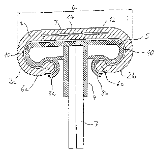
Fig. 1 shows a cross-section through the guide rail with the
hand rail mounted thereon according to a first embodiment of
the invention.
Fig. 2 shows a partial cross-section through a guide rail
with the hand rail mounted thereon according to a second
embodiment of the invention.
On Fig. 1, the upper part of a glass balustrade 7 can still
be seen. To this is fixed a guide rail 4 composed of
plastics material or metal, which has approximately a T-
shaped cross-section. For the purpose of saving material,
the lateral wings of the crossbeam 5 are hollow. On the
exterior, the guide rail has a surface or surface coating
which has as low a coefficient of friction as possible. On
the underside of the two crossbeams 5, the guide element in
each case has a moulded web 8a, 8b, which together with the
underside of the crossbeam forms a track or guide groove..
The hand rail of C-shaped cross-section consists
substantially of a flexible base body 1, which with its
CA 02580699 2007-03-16
7
flexible side lips 2a, 2b engages around the crossbeam 5 of
the guide rail. At the ends of the lips, there are
thickenings 6a, 6b which are inserted into the guide grooves
of the guide rail and are held there with positive locking
against lateral slipping out. Preferably the undercut of
the guide groove or track is so small that the bulge-like
thickenings 6a, 6b can be pressed with moderate force into
their respective track. According to the formation of the
track and of the undercut, the force which secures the lips
against slipping out may be greater than the force required
for pressing in. At the same time, the friction contact
between the thickenings 6a, 6b and the moulded webs 8a, 8b
is relatively low so that the hand rail can slide over the
guide rail.
On the side associated with the guide rail, the flexible
base body is covered with a sliding covering composed of a
textile braid or plastics coating with a low coefficient of
friction. Due to the lack of transverse stiffening, the
hand rail fits snugly on to the guide rail. Therefore, the
guide rail now serves the purpose of supporting the hand
rail against the pressure of the person being conveyed.
On the other side is a hand support face 14. This is formed
to be visually appealing with a coloured imprint and/or is
provided with a surface structure which is easy to grip.
The flexible base body can also be covered with a further
coating, which e.g. has anti-microbial properties and is
impregnated with aromatic substances.
Only in the middle region of the flexible base body is this
reinforced with a tie beam 12 of steel, cord or sheet metal.
CA 02580699 2007-03-16
8
The regions extending beyond the central region with the tie
beam are therefore flexible and abut the crossbeam of the
guide rail, whilst they are held at their ends 6a, 6b by the
longitudinal webs 8a, 8b on the underside of the guide rail.
The flexible base body may have both a C-shaped original
shape and be manufactured as a flat band-shaped formation.
Dimensional stability is not necessary.
In Fig. 2, an alternative embodiment is shown.
Corresponding parts are in this case characterised by the
same reference numbers as in Fig. 1. The side lip 2a of the
flexible base body in this case has no thickening at its end
but a region of uniform thickness with a head member 18,
which is bent however at 90 relative to the lip. This
structure can also be manufactured by extrusion. Thus at
the end of the lip a kind of projection 20 is formed. On
the guide rail 4, a correspondingly formed guide web 8a is
disposed. This is likewise bent over at its end and thus
forms an undercut 16, which cooperates with the projection
20 in order to prevent the head 18 from slipping out. Thus
a positive connection is created between the flexible base
body and the guide rail 4.
The driving of the hand rail is effected e.g. by a wide
friction wheel or by a print roller drive (not shown).