Note: Descriptions are shown in the official language in which they were submitted.
CA 02581259 2012-07-25
ESOPHAGUS IMAGING ENHANCEMENT DEVICE
FIELD OF THE INVENTION
The present invention relates generally to medical and therapeutic systems,
and
particularly to methods and devices for enhancing the imaging quality of
organs during
therapeutic procedures.
BACKGROUND OF THE INVENTION
Catheter-based cardiac procedures such as cardiac ablation may sometimes cause
damage to the esophagus, since sections of the esophagus often pass in close
proximity to
the left atrium and coronary sinus. The anatomical proximity of the left
atrium to the
esophagus is described, for example, by Lemola et al., in "Computed
Tomographic
Analysis of the Anatomy of the Left Atrium and the Esophagus: Implications for
Left
Atrial Catheter Ablation," Circulation, (110:24), December 14, 2004, pages
3655-60. The
proximity of the coronary sinus to the esophagus is described, for example, by
Tsao et al.,
in "Anatomic Proximity of the Esophagus to the Coronary Sinus: Implication for
Catheter
Ablation Within the Coronary Sinus," to be published in the Journal of
Cardiovascular
Electrophysiology, (17:4), April, 2006.
Some methods and systems are known in the art for enhancing the safety of such
procedures. For example, Pollak et al., describe imaging techniques for
imaging the
esophagus in a report entitled "Novel Imaging Techniques of the Esophagus
Enhancing
Safety of Left Atrial Ablation," Journal of Cardiovascular Electrophysiology,
(16:3),
March, 2005, pages 244-248.
The report describes imaging techniques performed during radio-frequency (RF)
catheter ablation of atrial fibrillation in the left atrium. According to the
report, a mixture
of barium cream and gadolinium diglutamate allowed esophageal imaging during
magnetic resonance angiography of the left atrium and pulmonary veins. In
another
technique, barium cream used during computer tomography angiographic imaging
of the
left atrium and pulmonary veins allowed esophageal imaging. The esophagus was
also
1
CA 02581259 2012-07-25
imaged with an electroanatomic mapping system. According to the report,
esophageal and
left atrial imaging helped to avoid catheter ablation in left atrial tissue
overlapping the
esophagus.
Wu and Wang describe a method of using left atrial esophagus imaging for a
balloon valvuloplasty application in a report entitled "Using Left Atrial
Esophagus
Impression After a Barium Swallow to Determine the Optimal Septal Puncture
Site
During Percutaneous Balloon Mitral Valvuloplasty," Canadian Journal of
Cardiology,
(19:13), December, 2003, pages 1509-1512. The study describes methods for
transseptal
catheterization for percutaneous balloon mitral valvuloplasty (PBMV)
procedures. The
left atrial (LA) impression on the esophagus after a barium swallow was used
as a
reference of LA silhouette to determine the septal puncture site.
SUMMARY OF THE INVENTION
In some medical procedures, such as cardiac ablation, it is desirable to
enhance
the imaging quality of an organ. For example, when performing ablation in the
left
atrium, it is desirable to enhance the imaging quality of the esophagus in
order to avoid
ablating regions of the endocardium adjacent to the esophagus.
The present invention provides a marker device for enhancing visualization of
an
organ of a patient when imaged by a visualization system, the device
comprising: a
structure comprising material that is visible when imaged by the visualization
system,
wherein the material is adapted to self-expand and self-conform to an inner
surface of the
organ in order to mark the surface of the organ so that the surface is visible
when imaged
by the visualization system.
Thus, embodiments of the present invention provide devices for enhancing the
visualization quality of an organ when imaged by a visualization system. The
visualization system may comprise an imaging system, a mapping system, or
both. The
disclosed devices comprise a structure comprising material that is clearly
visible when
imaged by the visualization system. The structure is inserted into the organ
and
2
CA 02581259 2007-03-06
self-conforms to an inner surface of the organ, in order to enhance the
visualization
quality of the surface when using the visualization system.
In some embodiments, position sensors are attached to the device in order to
enable position tracking and/or registration of the image of the organ with
images
from other sources.
There is therefore provided, in accordance with an embodiment of the present
invention, a device for enhancing visualization of an esophagus when imaged by
a
visualization system, the device including:
a structure including material that is clearly visible when imaged by the
visualization system, which is arranged, when inserted into the esophagus, to
expand
so as to conform with an inner surface of the esophagus in order to enhance a
visualization quality of the surface when imaged by the visualization system;
and
a cord attached to the structure, which is arranged to extend out of the
esophagus so as to assist a removal of the device from the esophagus.
In an embodiment, the structure includes a metallic wire grid. Additionally or
alternatively, the structure may include at least one of a compressible coil,
a spring
and a flexible mesh tube. In another embodiment, the device includes one or
more
position sensors, which are attached to the structure and are adapted to
provide
position coordinates to the visualization system.
There is also provided, in accordance with an embodiment of the present
invention, a device for enhancing visualization of an esophagus, the device
including:
a structure that is arranged, when inserted into the esophagus, to expand so
as
to conform with an inner surface of the esophagus; and
one or more position sensors, which are attached to the structure and are
arranged to produce respective position signals so as to enable a position
tracking
3
CA 02581259 2007-03-06
system to calculate respective positions of the one or more position sensors
within the
esophagus.
In an embodiment, the position sensors are arranged to sense magnetic fields
generated by a magnetic position tracking system and to produce the position
signals
respectively to the sensed fields. In another embodiment, the position sensors
are
arranged to sense electrical signals generated by an impedance-based position
tracking
system and to produce the position signals respectively to the sensed
electrical signals.
There is additionally provided, in accordance with an embodiment of the
present invention, a device for enhancing visualization of an organ, the
device
including:
a structure that is arranged, when inserted into the organ, to expand so as to
conform with an inner surface of the organ; and
one or more position sensors attached to the structure and are arranged to
produce respective position signals so as to enable a position tracking system
to
calculate respective positions of the one or more position sensors within the
organ.
There is further provided, in accordance with an embodiment of the present
invention, a system for treating a patient, including:
a visualization system, which is arranged to image at least part of a body of
a
patient; and
a marker device including a structure that is arranged, when inserted into an
esophagus of the patient, to expand so as to conform with an inner surface of
the
esophagus in order to enhance a visualization quality of the surface when
imaged by
the visualization system.
In an embodiment, the mapping system includes at least one of a magnetic
position tracking system and an impedance-based position tracking system.
4
CA 02581259 2007-03-06
In another embodiment, the visualization system includes an imaging system
operative to image the esophagus in addition to the mapping system, and the
visualization system is arranged to register the position coordinates of the
position
sensors with images produced by the imaging system and to jointly display the
position coordinates and the images to a physician.
In yet another embodiment, the system includes a catheter, which is adapted to
be inserted into a heart of the patient for performing a medical procedure in
the heart,
and the visualization system is arranged to determine relative positions of
the catheter
and the esophagus. In still another embodiment, the visualization system is
arranged to
detect an alert condition related to the procedure responsively to the
relative positions
and to alert a physician when the alert condition is detected.
There is additionally provided, in accordance with an embodiment of the
present invention, a system for treating a patient, including:
a visualization system, which is arranged to image at least part of a body of
a
patient; and
a marker device including a structure including material that is clearly
visible
when imaged by the visualization system, which is arranged, when inserted into
an
organ of the patient, to expand so as to conform with an inner surface of the
organ in
order to enhance a visualization quality of the surface when imaged by the
visualization system.
There is also provided, in accordance with an embodiment of the present
invention, a method for treating a patient, including:
inserting into an esophagus of the patient a marker device including a
structure
that is arranged to expand so as to conform with an inner surface of the
esophagus;
forming an image of a thorax of the patient in which the structure in the
esophagus indicates a locus of the esophagus in the image; and
performing a medical procedure in the thorax of the patient using the image.
5
CA 02581259 2007-03-06
In an embodiment, performing the medical procedure includes at least one of
preplanning the procedure and verifying a result of the procedure using the
image.
There is further provided, in accordance with an embodiment of the present
invention, a method for treating a patient, including:
inserting into an organ of the patient a marker device including a structure
that
is arranged to expand so as to conform with an inner surface of the organ;
forming an image of at least part of a body of the patient in which the
structure
in the organ indicates a locus of the organ in the image; and
performing a medical procedure in the at least part of the body of the patient
using the image.
The present invention will be more fully understood from the following
detailed description of the embodiments thereof, taken together with the
drawings in
which:
BRIEF DESCRIPTION OF THE DRAWINGS
Fig. 1 is a schematic, pictorial illustration of a system for performing
cardiac
ablation, in accordance with an embodiment of the present invention;
Figs. 2A and 2B are schematic, pictorial illustrations of a device for
visualizing an esophagus, in accordance with an embodiment of the present
invention;
and
Fig. 3 is a flow chart that schematically illustrates a method for performing
cardiac ablation while visualizing the esophagus, in accordance with an
embodiment
of the present invention.
DETAILED DESCRIPTION OF EMBODIMENTS
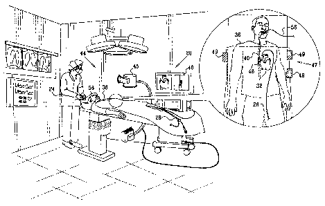
Fig. 1 is a schematic, pictorial illustration of a system 20 for performing
cardiac ablation, in accordance with an embodiment of the present invention. A
6
CA 02581259 2007-03-06
physician 24 inserts a catheter 28 into a heart 32 of a patient 36 in order to
perform a
cardiac ablation procedure. Catheter 28 typically comprises an ablation
electrode,
which applies concentrated RF energy to selected spots on the endocardium (the
inner
surface of the heart), as is known in the art.
In some cases, parts of an esophagus 40 of the patient may overlap, or be
adjacent to, parts of heart 32, and in particular the posterior part of the
left atrium and
the coronary sinus. Because of this proximity, the ablation procedure may
cause
thermal damage to the esophagus, sometimes resulting in its perforation.
In order to prevent damage from being caused to the esophagus, a visualization
system 44 provides the physician with an image of at least part of the
patient's body,
typically comprising the heart and the parts of the esophagus that are in
close
proximity to the heart. The visualization system displays images showing the
positions
of the cardiac chamber in which the ablation procedure takes place, the
catheter
performing the procedure, and the region of the esophagus adjacent to the
heart. Using
these images, the physician is able to plan and perform the ablation procedure
while
avoiding areas of the endocardium that are in close proximity to the
esophagus.
In some embodiments, system 44 comprises an imaging system 45. The
imaging system uses a certain imaging modality, in which body parts and
features are
imaged responsively to differences in their material composition and/or their
chemical
or physical properties. For example, system 45 may comprise a fluoroscopic
imaging
system in which body parts of the patient are irradiated with x-rays. The x-
ray
radiation transmitted through the body is received by detectors and used to
reconstruct
images of the irradiated body parts. Other examples of imaging modalities
comprise
ultrasonic, computerized tomography (CT) and magnetic resonance imaging (MRI)
systems. Typically, imaging modalities also enable tracking the position of
catheter
28, by virtue of its different material composition and physical properties.
7
CA 02581259 2012-07-25
Additionally or alternatively, system 44 comprises a mapping system 47,
which uses a certain mapping modality in which the system tracks the positions
of
dedicated intrabody sensors. For example, a sensor can be fitted in catheter
28.
System 47 then tracks the positions of the sensor in order to map the desired
organs
and display the current position of the catheter relative to the map. The map
may be
registered with and superimposed on images captured by imaging system 45.
For example, mapping system 47 may comprise a magnetic position tracking
system, which tracks position sensors, such as coils, fitted into catheters
and/or other
intrabody objects. Some systems and methods for magnetic position tracking are
described, for example, in PCT Patent Publication WO 96/05768, U.S. Patents
5,391,199, 5,443,489, 6,690,963, 6,239,724, 6,618,612 and 6,332,089, and U.S.
Patent Application Publications 2002/0065455 Al, 2003/0120150 Al and
2004/0068178 Al.
Referring to the exemplary configuration of Fig. 1, magnetic position tracking
system 47 comprises field-generating coils 49, which generate magnetic fields
in a
working volume that includes the relevant parts of the heart and esophagus.
System
47 tracks sensors fitted into catheter 28 and into a device inserted into the
esophagus,
as will be explained below. The sensors sense the magnetic fields generated by
coils
49 and produce respective position tracking signals, which are indicative of
the sensor
positions. By tracking the positions of the sensors, system 47 can present the
position
of the catheter with respect to the esophagus and heart to the physician.
As another example of a mapping modality, system 47 may comprise an
impedance-based position tracking system, which tracks the position of an
electrode
attached to an intrabody object. The electrode senses an electrical signal
transmitted
through the body tissue from externally attached transducers. Exemplary
impedance-
based tracking systems are described in U.S. Patents 5,983,126, 6,456,864, and
5,944,022, and in U.S. Patent Application 11/030,934 filed on January 7, 2005.
8
CA 02581259 2012-07-25
Alternatively or additionally, visualization system 44 may use any other
suitable imaging and/or mapping modality known in the art, or a combination of
such
modalities. System 44 comprises a display 46, which presents the imaged heart,
esophagus and catheter to the physician.
In order to enhance the visualization quality of the esophagus by
visualization
system 44, an esophagus marker device 48 is inserted into the region of the
esophagus
adjacent to the heart. In principle, device 48 is constructed so as to enable
it to self-
conform to the inner surface of the esophagus. Device 48 is constructed, as
described
in detail hereinbelow, so that the device is clearly visible when imaged by
the
visualization system. Thus, once inserted and self-aligned with the surface of
the
esophagus, device 48 marks the surface of the esophagus so that the surface is
displayed clearly and accurately by the visualization system.
An exemplary embodiment of device 48 is described in detail with reference
to Figs. 2A and 2B below. As will be explained, the characteristics of marker
device
48 should match the modality used, so that the marker device will be imaged
clearly
by visualization system 44.
Figs. 2A and 2B are schematic, pictorial illustrations of marker device 48, in
accordance with an embodiment of the present invention. In this embodiment,
device
48 comprises a resilient grid 52 of material that is clearly visible when
imaged by
imaging system 45. For example, when imaging system 45 comprises a
fluoroscopic
imaging system, grid 52 may comprise flexible metallic wires. As another
example,
echogenic polymer coating can be used to enhance the visualization under intra-
cardiac ultrasound guidance. In alternative embodiments, device 48 may
comprise any
suitable structure, comprising material that is clearly imaged by imaging
system 45,
9
CA 02581259 2007-03-06
which self-conforms to the inner surface of the esophagus. For example, device
48
may comprise a compressible coil or spring or a flexible mesh tube (stent).
Fig. 2A
shows device 48 with grid 52 shown fully flattened in order to demonstrate its
structure. In some embodiments, grid 52 is folded, rolled, wound, contracted
or
otherwise tightened in order to enable it to be inserted into the esophagus of
the
patient. Device 48 is inserted through the patient's mouth into the esophagus.
When
reaching the desired region of the esophagus (e.g., the region next to the
heart), the
device is allowed to self-extract and self-conform to the inner surface of the
esophagus.
In some embodiments, device 48 is initially held in its tightened form using
an
external sheath (not shown). After inserting the device, the external sheath
is gradually
pulled back and the device is allowed to self-extract and self-conform to the
inner
surface of the esophagus. In these embodiments, device 48 can be removed by
pulling
it back into the external sheath. In an alternative embodiment, device 48 can
be
expanded to fit the inner surface of the esophagus by inflating a balloon
inserted into
the tightened device, and subsequently removed by deflation. The balloon may
also be
filled with hot water, thereby causing device 48 to shrink back into its
tightened form,
enabling its safe retrieval.
In some embodiments, device 48 comprises a cord 56, which is connected at
one end to grid 52. When device 48 is inserted into the esophagus, cord 52
extends out
of the patient's mouth so as to allow device 48 to be pulled out after the
procedure is
completed. In some cases, cord 56 can also be used to provide an estimate of
the depth
of device 48 in the esophagus.
Fig. 2B shows device 48 after it was inserted and has self-aligned with the
inner surface of esophagus 40. It can be seen that device 48 follows the
contours of
the esophagus closely, thereby effectively marking the exact shape and
location of the
esophagus in a manner that is clearly imaged by imaging system 45.
CA 02581259 2007-03-06
In some embodiments, when visualization system 44 comprises a mapping
system 47, one or more sensors 60 may be attached to grid 52 of device 48. For
example, when system 44 comprises a magnetic position tracking system, sensors
60
comprise position sensors, such as field sensing coils, that sense the
magnetic fields
generated by mapping system 47. The position sensors translate the sensed
fields to
respective position signals that are transmitted back to system 47. Mapping
system 47
uses the position signals to calculate the positions of the position sensors.
As another
example, when mapping system 47 comprises an impedance-based tracking system,
3.0 sensors 60 comprise suitable potential-sensing electrodes.
Sensors 60 may be connected to mapping system 47 using wires (not shown)
traveling along cord 56. A similar sensor 60 is fitted in the distal end of
catheter 28.
Fig. 2B shows catheter 28 inserted into the heart and located next to the
endocardium,
in close proximity to esophagus 40. By tracking the positions of the sensors,
mapping
system 47 is able to calculate and display the coordinates of catheter 28 with
respect to
several points of reference in device 48. The physician can use this relative
display to
avoid ablating spots on the endocardium that are too close to the esophagus.
Although
Figs. 2A and 2B show two sensors 60 attached to device 48, any number of
sensors
can be attached to grid 52.
When mapping system 47 comprises a magnetic position tracking system,
sensors 60 may also be used to register the image of the grid with a three-
dimensional
map of the heart generated by imaging system 45. In some embodiments, the
sensor
measurements can be used to register the image of device 48 with another 3-D
image
(either a real-time image or a pre-acquired image) of the heart.
Fig. 3 is a flow chart that schematically illustrates a method for performing
cardiac ablation while visualizing the esophagus, in accordance with an
embodiment
of the present invention. The method begins with the physician inserting
esophagus
11
CA 02581259 2012-07-25
marker device 48 into esophagus 40 of patient 36, at an insertion step 80.
After
inserting the device to the desired region of the esophagus, the device is
allowed to
self-extract and self-conform to the inner surface of the esophagus.
The physician uses visualization system 44 to image at least part of the
patient's body, at an imaging step 82. Typically, the imaged volume comprises
the
heart and the parts of the esophagus adjacent to the heart. The visualization
system
displays esophagus 40, whose visualization quality has been enhanced by device
48.
System 44 also displays heart 24 and catheter 28 inserted into it.
In some embodiments, the physician may preplan the ablation procedure using
the visualized organs, at a preplanning step 83. Aspects of ablation
preplanning are
described, for example, in U.S. Patent Application 11/195,050, filed August 2,
2005,
now U.S. Patent No. 7,877,128.
Assisted by the display of visualization system 44, the physician performs the
cardiac ablation procedure, at an ablation step 86. The images of the heart,
esophagus
and catheter enables the physician to avoid spots on the endocardium that are
dangerously close to the esophagus, thus increasing the safety of the
procedure.
Aspects of online guidance of ablation procedures are described, for example,
in U.S.
Patent Application Publication 2004/0078036 Al, and in U.S. Patent Application
11/195,123, filed August 2, 2005, now U.S. Patent No. 7,681,579.
In some embodiments, the visualization system may automatically alert the
physician in real-time when the catheter location is considered dangerous,
i.e., too
close to the esophagus. When system 44 comprises a position tracking system,
for
example, an alert condition can be detected responsively to position-tracking
measurements of the sensor 60 in catheter 28 relative to the sensors 60
attached to
device 48. The alert may comprise any suitable means to attract the
physician's
attention, such as an audible alarm, a change of color or other visual
indication on
display 46.
12
CA 02581259 2012-07-25
, .
After the ablation procedure is completed, the physician removes device 48
from the esophagus, through the patient's mouth, at a removal step 88. In some
embodiments, the physician may assess and/or validate the results of the
ablation
procedure, at a validation step 90. Exemplary assessment and validation
methods are
described in U.S. Patent Application Publication 2004/0147920 Al.
It will be appreciated that the embodiments described above are cited by way
of example, and that the present invention is not limited to what has been
particularly
shown and described hereinabove. Rather, the present invention includes both
combinations and sub-combinations of the various features described
hereinabove, as
well as variations and modifications thereof which would occur to persons
skilled in
the art upon reading the foregoing description and which are not disclosed in
the prior
art.
13