Note: Descriptions are shown in the official language in which they were submitted.
. . .... .. . . ...... . . ~ . .
CA 02581650 2007-03-13
1
METHOD FOR THE DEI'ERMINATION OF A PROGRESSIVE
OPI~THALMIC LENS
The present invention relates jto a method for the determination of a
progressive
ophthalniic lens; in particular a progressive lens personalized for the
specific needs
of a given wearer_
Any ophthalmic lens intendO to be held in a frame involves a prescription.
The ophthalmic prescription can iixclude a positive or negative power
prescription as
well as an astigmatism prescription. These prescriptions correspond to
corrections
enabling the wearer of the lenses to correct defects of his vision. A lens is
fitted in
the frame in accordance with the prescription and the position of the wearer's
eyes
relative to the frame.
For presbyopic wearers, the: value of the power correction is different for
far
vision and near vision, due to the; difficulties of accommodation in near
vision. The
prescription thus comprises a fair-vision power value and an addition (or
power
progression) representing the power increment between far vision and near
vision;
this comes down to a far-vision power prescription and a near-vision power
prescription. Lenses suitable for presbyopic wearers are progressive
multifocal
lenses; these lenses are describedl for example in FR-A-2 699 294, US-A-5 270
745
or US-A-5 272 495, FR-A-2 683 ~42, FR-A-2 699 294 or also FR-A-2 704 327.
Progressive multifocal ophthalmic lenses include a far-vision zone, a near-
vision zone, an intermediate-visifan zone, a principal progression meridian
crossing
these three zones. They are gene~ally determined by optimization, based on a
certain
number of constraints imposed on the different characteristics of the lens.
Most
marketed lenses are all-purpose ljenses, in that they are adapted to the
different needs
of the wearers at the time.
A progressive multifocal lons can be defined by geometric characteristics on
at
least one of its aspherical surfac~s. In order to characterize an aspherical
surface, the
parameters constituted by the 0inimum and maximum curvatures at each point are
conventionally used, or more qommonly their half-sum and their difference.
This
half-sum and this difference murltiplied by a factor n-l, n being the
refractive index
of the lens material, are called mjean sphere and cylinder.
Moreover, a progressive, multifocal lens can also be defined by optical
characteristics taking into accoont the situation of the wearer of the lenses.
In fact,
the laws of the optics of ray tracings provide that optical defects appear
when the
rays deviate from the central axi,s of any lens. Conventionally, the
aberrations known
R:\Brevets124800\24857-070219-hadfXl'GB-doc-22 (evtier 4007. 1114
CA 02581650 2007-03-13
2
as power defects and astigmatism defects are considered. These optical
aberrations
can be generically called obliquity ~efects of rays.
Obliquity defects of rays have already been clearly identified in the prior
art
and improvements have been proposed. For example, the document WO-A-98 12590
describes a method for determin4tion by optimization of a set of progressive
multifocal ophthalmic lenses. This 'idocument proposes defining the set of
lenses by
considering the optical characteri$tics of the lenses and in particular the
wearer
power and oblique astigmatism, un4er wearing conditions. The lens is optimized
by
ray tracing, using an ergorama assojciating a target object point with each
direction of
viewing under wearing conditions.
EP-A-0 990 939 also proposos to determine a lens by optimization taking into
account the optical characteristics 'instead of the surface characteristics of
the lens.
For this purpose the characteristicsiof an average wearer are considered, in
particular
as regards the position of the lens: in front of the wearer's eye in terms of
curving
contour, pantoscopic angle and lens-eye distance.
It has been found that each wearer has different lens-eye behaviour. Recently
therefore it has been sought to per$onalize progressive ophthalmic lenses in
order to
best satisfy the needs of each wearer.
For example, it is proposed, Mn particular by ZEISS and RODENSTOCK under
the references Zeiss IndividualO ahd Impression ILT respectively, to take
account,
for the definition of progressive leplses, of the real position of the lens in
front of the
wearer's eye. For this purpose, me#a.surements of the position of the lens in
the frame
chosen by the wearer are carried ;out. The measurement of the position of the
lens
relative to the wearer's eye is initially difficult to carry out with
precision. Then, the
optimization is carried out for a measured position of the lens in front of
the wearer's
eye; it turns out that the positiqn of the frame varies over time and cannot
be
considered to be constant for a igiven wearer- Because of these two factors,
the
consideration of the position of ihe lens does not seem to provide the wearer
an
additional comfort compared to sblutions which consider only the mean position
of
the lens.
The applicant markets, undjer the trade mark VARILUX IPSEO a range of
progressive lenses, which are 4iefined as a function of the wearer's head-eye
behaviour. This definition is baso on the fact that any wearer, in order to
look at
different points at a given height in the object space, can move either his
head, or his
eyes and that the viewing strategy of a wearer is based on a combination of
head and
eye movements. The wearer's viekwing strategy influences the perceived width
of the
fields on the lens. Thus, the more the wearei-'s lateral vision strategy
involves a
movement of the head, the nano1wer is the zone of the lens scanned by the
wearer's
R1Btevets\24800\2485 7-0702 19-tradTXTGB.doc - 22 Cdvrier 200'J - 2114
CA 02581650 2007-03-13
3
vision. If the wearer moved only his head in order to look at different points
at a
given height of the object space, his vision would still pass through the same
point of
the lens. The product VARILUX IPSEO therefore proposes different lenses, for
the
same ametropia-addition pair, as a f6nction of the wearer's lateral vision
strategy.
Moreover, the documents UIS-A-6 637 880 and US-A-6 871 955 describe
ophthalmic lenses optimized by tak ing into account the real position of the
centre of
rotation of the wearer's eye, referenced CRE. The lens-CRE distance is defined
as
the sum of the distance lens-cornoa. (referenced VC) and cornea-CRE
(referenced
CR). The value VC is a function of'the wearing conditions and the value CR is
linked
to the measurement of the axial leogth of the eye. The axial length can be
measured
by the optician or by the optometri5t for each individual and the position of
the CRE
is deduced from this by a rule of three. The axial length of the eye can be
measured
for example with the device marketjed under the trade mark IOLMaster by
ZEISS.
For the optimization of progriessive ophthalmic lenses, documents US-A-6 637
880 and US-A-6 871 955 propose taking into account the fact that the CRE is
situated at different distances when the wearer is looking in far vision, in
near vision
or in any other point of the lens aW to integrate it in the optimization. For
example, it
is indicated that a change of the leos-CRE distance has an impact on the
lateral shift
in near vision; the optical design i$ therefore calculated as a function of
this value. It
is also indicated that the lens-CRE distance has an impact on the power
required in
far vision; the asphericity of the leos is therefore modified as a function of
this value.
The applicant has also deveqoped a device for measuring the position of the
centre of rotation of the eye of a given individual, which is the subject of
the French
Patent Application filed by the applicant under the title Method and device
for the
determination of the centre of rotation of an eye on 08 April 2005 under
number FR
05 50902 (now published under number FR-A-2 884 130).
The measurements of the axial length of the eye or of the centre of rotation
of
the eye are carried out by the optician or the optometrist; they are difficult
to carry
out and the apparatus is relatively expensive. In addition, these measurements
are not
used to determine the distributions of power and resulting astigmatism defects
on the
optimized lens.
Tests carried out in the applicant's laboratories have shown that the axial
length of the eye influences the wearer's perception of the fields and
gradients. A
need still exists therefore for a lebs which better satisfies the specific
needs of each
individual wearer.
The invention consequent y proposes taking into account the wearer's
ametropia in order to determine t e axial length of the eye and its centre of
rotation
in order to avoid complex measurements on the wearer. The invention then
proposes
R1Brevetst24800t74837-070ZI9-tradTXTGB.doc - ZZ fCVfier 2007- YI4
i
CA 02581650 2007-03-13
4
taking account of this axial length in order to determine the power and
resulting
astigmatism defect fields and gradients on the optimized lens. The wearer's
visual
comfort can thus be improved.
The invention more particula>Cly proposes a method for the determination of a
progressive ophthalmic lens personolized for a given wearer who has been
prescribed
a far-vision power (AFv) and who ihas been prescribed a power addition (Add)
for
near vision, the method comprising the stages of
- determining the axial length i(LA) of the wearer's eye;
- determining an ergorama ajssociating a sight point with each direction of
viewing under wearing conditions;
- determining power and resulting astigmatism defect targets for each
direction
of viewing under wearing conditions, the targets being a function of the axial
length
of the wearer's eye;
- calculating the power required on the lens for each direction of viewing by
successive iterations in order to obtain the target power defect and the
target resulting
astigmatism.
According to one embodimeot, the stage of determining the axial length (LA)
of the eye is carried out using the fajr vision prescription (AFV) given to
the wearer.
According to one embodimeot, the stage of determining the axial length of the
eye (LA) is carried out using the fat vision prescription (AFv) given to the
wearer and
the measurement of the radius of the wearer's cornea (kerato).
According to an embodiment, a position of the centre of rotation of the eye
(CRE) is calculated using the determined axial length of the eye.
According to an embodimenit, the stage of determining the targets comprises
determining the power and resulting astigmatism defect gradients and
determining
the power and resulting astigmatism defect field widths.
The invention also relates to a personalized progressive ophthalmic lens
obtained by the method of deterinining the invention, as well as a visual
device
comprising at least one lens ac,~,ording to the invention and a method for the
correction of the vision of a prejsbyopic subject, which comprises providing
the
subject with, or the wearing by the~ subject of, such a device.
Other advantages and featqres of the invention will become apparent on
reading the following description of the embodiments of the invention, given
by way
of example and with reference to the drawings which show:
- Figure 1, a diagram of an eye-lens optical system, as a top view;
- Figures 2 and 3, perspectivo diagrams of an eye-lens system;
- Figure 4, a diagram illustitating the transfer function between a
progressive
ophthalmic lens and the retina;
R:\BreveLs\24800\24857-070219-trsdTYTGB.doc - 22 fevrier 2007 . 4'14
CA 02581650 2007-03-13
- Figures 5a and 5b, diagrams illustrating respectively the gradients
projected
on the retina and the field widths p'erceived by the wearer as a function of
the axial
length of the eye;
- Figure 6, a graph of the relajtive variation of gradient and field with the
axial
5 length of the eye;
- Figure 7, a graph showing axial length measurements correlated to the
ametropia of the wearers;
- Figure 8, a graph showing measurements of the ratio of the axial length of
the
eye over the keratometry correlatedi to the ametropia of the wearers.
- Figure 9, a cylinder map of a lens according to the invention intended for a
hypermetropic wearer;
- Figure 10, a cylinder map of a lens according to the invention intended for
a
myopic wearer.
The invention proposes asnethod for the determination of a progressive
ophthalmic lens for a presbyopic wearer, i.e. for whom a power addition Add
has
been prescribed for near vision.
In a manner known per se, a progressive lens has a far-vision zone with a
control point FV, a near-vision zoine with a control point NV and an
intermediate-
vision zone. A principal progre$sion meridian crosses these three zones. The
meridian therefore has a power pn,ogression between the control point in far
vision
FV and the control point in near vision NV; this progression corresponds
approximately to the value of the prescribed addition Add. A fitting cross CM
is
marked by a reference point on tho complex surface and constitutes an aid for
fitting
the cut-out lens into the frame; thls fitting cross CM makes it possible to
locate on
the lens the primary direction of viewing under wearing conditions. In this
context,
progression length PL refers to the:vertical distance between the fitting
cross CM and
the point of the meridian in near titision NV at which the power progression
reaches
the power Add. The progression length PL defines the accessibility to the
powers
necessary in near vision.
In a conventional manner, for a given lens, characteristic optical variables
are
defined, namely a power and a resulting astigmatism, under wearing conditions.
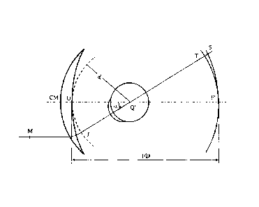
Figure I shows a diagram of an eyo and lens optical system as a side view, and
shows
the definitions used in the rest of the description. The centre of rotation of
the eye is
called Q'; the axis Q'F' represented in the figure by a chain-dotted line is
the
horizontal axis passing through the centre of rotation of the eye and
continuing in
front of the wearer - in other words the axis Q'F corresponds to the primary
viewing
direction. This axis cuts, on the front face, a poiiit on the lens called the
fitting cross
CM, which is marked on the lenses in order to allow their positioning by an
optician.
R\sreve7S\24800\2as37-a702t9-t1ad77fTCiB.doc- 22 [Cvrier 2007-Y14
CA 02581650 2007-03-13
6
Let point 0 be the point of intersection of the rear face and this axis Q'F'.
A sphere of
the vertices is defined, with a cen0e Q', and a radius q', which cuts the rear
face of
the lens at the point O. By way of example, a radius q' value of 27 mm
corresponds
to a current value and produces satisfactory results when the lenses are worn.
The
section of the lens can be drawn in #he plane (0, x, y) which is defined with
reference
to Figure 2. The tangent to this curve at the point 0 is inclined relative to
the axis
(0, y) at an angle called the pantospopic angle. The value of the pantoscopic
angle is
currently 8 . The section of the leps can also be drawn in the plane (0, x,
z). The
tangent to this curve at the point 0 is inclined relative to the axis (0, z)
at an angle
called the curving contour. The valpe of the curving contour is currently 0 .
A given direction of viewithg - represented by a solid line in Figure 1-
corresponds to a position of the eye in rotation about Q' and to a point J on
the sphere
of the vertices; a direction of viewling can also be marked, in spherical
coordinates,
by two angles a and 0. The angle a ' is the angle formed between the axis Q'F'
and the
projection of the straight line Q'J 4ver the horizontal plane containing the
axis Q'F';
this angle appears in the diagrain of Figure 1. The angle 0 is the angle
formed
between the axis Q'F' and the prpjection of the straight line Q'J over the
vertical
plane containing the axis Q'F'. A gNven direction of viewing therefore
corresponds to
a point J of the sphere of the vertic*s or to a pair (a, (3)-
In a given direction of vieWing, the image of a point M in the object space
situated at a given object distance,forms between two points S and T
corresponding
to minimum and maximum distar#ces JS and JT (which are sagittal and tangential
focal distances in the case of revopution surfaces, and of a point M at
infinity). The
angle y marked as the axis ofastigmatism is the angle formed by the image
corresponding to the smallest di$tance with the axis (z.), in the plane (zm,
ym)
defined with reference to Fipres 2 and 3. The angle y is measured in
counterclockwise direction when I ooking at the wearer. In the example of
Figure 1,
on the axis Q'F', the image of a po#nt of the object space at infinity forms
at the point
F'; the points S and T coincide, whiich is another way of saying that the lens
is locally
spherical in the primary direction of viewing_ The distance D is the rear
front end of
the lens.
Figures 2 and 3 show perspective diagrams of an eye-lens system. Figure 2
shows the position of the eye and of the reference point linked to the eye, in
the
principal viewing direction, a - 0 = 0, called the primary viewing direction.
The
points J and 0 thus coincide. Fipre 3 shows the position of the eye and of the
reference point which is linked to it in one direction (a, {i)_ In Figures 2
and 3 a fixed
reference {x, y, z) and a reference (xm,ym,zm) linked to the eye are
represented, in
order to show the rotation of the cye clearly. The origin of the reference {x,
y, z) is
R'\Brevets\24800\24857-070219-trndTXTG$.doc - 22 fevrner 2007. 6114
i : .
CA 02581650 2007-03-13
7
the point Q'; the axis x is the axis IQ'F'- the point F' is not represented in
Figures 2
and 3 and passes through the point 0; this axis is orientated from the lens
towards the
eye, in agreement with the directioii of measurement of the axis of
astigmatism. The
plane {y, z} is the vertical plane; the y axis is vertical and orientated
upwards; the z
axis is horizontal, the reference being directly orthonormalized. The
reference {xm
ym, zm} linked to the eye has the point Q' as its centre; the axis xm is given
by the
direction JQ' of viewing, and coinoides with the reference {x, y, z) for the
primary
direction of viewing. Listing's law $ives the relationships between the
references {x,
y, z} and {x,,,, ym, zm}, for eadh direction of viewing, see Legrand, Optique
Physiologique, Volume 1, Edition de la Revue d'Optique, Paris 1965.
Using these data, optical power and astigmatism of the wearer can be defined
in each direction of viewing. For ai direction of viewing (a, 0), an object
point M at
an object distance given by the ergprama is considered. The points S and T
between
which the image of the object formis are determined. The image proximity PI is
then
given by
Pt= 1 1 + 1
2 JT JS
while the object proximity PO is given by
I
PO= -
MJ
The power is defined as the sum of the object and image proximities, i.e_
2o P=PO+PI= I+ I 1+ I
MJ 2 JT JS
The amplitude of the astigmatism is given by
A= 1
---
JT JS
The angle of the astigmatis#n is the angle y defined above: it is the angle
measured in a reference linked to the eye, relative to the direction zn,, with
which the
image T forms, in the plane (zm, ym). These definitions of power and of
astigmatism
are optical definitions, under wearing conditions and in a reference linked to
the eye.
Qualitatively, the thus-defined power and astigmatism correspond to the
characteristics of a thin lens, which, fitted instead of the lens in the
direction of
viewing, provides the same images locally. It is noted that, in the primary
direction
of viewing, the definition provides the standard value of the astigmatism
prescription. Such a prescription is produced by the ophthalmologist, in far
vision, in
the form of a pair formed by an a.xis value (in degrees) and an amplitude
value (in
diopters).
R\BreNets\24800124857-0', 0219-tradThTGB doc - 22 fevrier 2007 - ~'14
CA 02581650 2007-03-13
8
The thus-defined power and astigmatism can be experimentally measured on
the lens using a frontofocometer; they can also be calculated by ray tracing
under
wearing conditions.
The present invention proposes to take into account the geometry of the
wearer's eye in order to optimize a. progressive ophthalmic lens specifically
suited to
the wearer's needs. The taking into account of such individual parameters is
now
possible on an industrial scale thanks to the methods for direct machining of
the
complex surfaces constituting the ptogressive lenses.
Figure 4 illustrates the relatiolnship which exists between the design of the
lens
and its projection on the retina in the lens - eye system. Numerous eye models
have
been developed in order to defipe lens-eye systems and to allow the optical
optimization of progressive ophthalmic lenses. Reference can be made for
example
to the model defined in the publi"tion Accommodation dependent model of the
human eye with aspherics by R. Navarro, J. Santamaria and J. Bescos, Optical
Society of America., Vol. 2, No 8b August 1985. In the context of the
invention,
attention will be paid more particularly to the position and the shape of the
retina as
well as the position of the centre of rotation of the eye, referenced CRE.
Figure 4 shows an eye 10 h*ving an axial length LA. The eye is represented
with a cornea, a pupil and a retina; A lens 100 is placed in front of the eye
10. The
axial length of the eye LA is the eqrnea - retina distance. This axial length
is specific
to each individual and it has beenfound that it is closely correlated to the
wearer's
ametropia, as explained below. At the bottom of Figure 4 there is a
diagrammatic
representation of the resulting a~tigmatism defect of the lens and at the top
a
representation of the perception olf this resulting astigmatism on the retina
for the
different directions of viewing bebind the lens. Thus, using desirable optico-
retinal
quantities in terms of field widths and gradients, power and resulting
astigmatism
defect targets can be defined in order to optimize the progressive lens under
wearing
conditions.
The transfer function between the optimized lens under wearing conditions and
the retina depends on the biometriic parameters of the eye and in particular
the axial
length of the eye_ In fact, as illustroted in Figures 5a and 5b, the length of
the eye has
an impact on the gradients projected on the retina and on the width of the
fields
perceived. As illustrated in Figu1re 5a, when the eye is longer than an
average
emmetrope eye, i.e. has an axial 16 ngth equal to L + AL (AL>0), the retina is
situated
further away and has a more elong'ated shape than for an eye having an average
axial
length: in other words, the projection of a set of object points perceived
through the
lens is more spread out on the reti~a that for an eye having an average axial
length L_
The average axial length L of an cimmetrope eye is generally 24 mm. For a long
eye,
R:\Brevets\24800\24857-070219-ttadTXTGB.doc - 22 CEvrier 2007 - 8114
CA 02581650 2007-03-13
9
the sensation of gradient on the retina is therefore gentler. The power and
resulting
astigmatism defect gradients on the lens can therefore be stronger without
disturbing
a wearer having a long eye. Simit4rly, as illustrated in Figure 5b, when the
eye is
long, the position of the centre of riotation CRE is distanced proportionally
from the
pupil relative to an average emm$trope eye. The angle of rotation of the eye
for
perceiving an object through the same point of the lens is therefore reduced.
Thus,
the longer the eye the greater the seknsation of reduced field. The power and
resulting
astigmatism fields on the lens musttherefore be enlarged in order to provide a
wearer
having a long eye with good visual comfort. Inversely, in the case of a short
eye, the
sensation of gradients on the retina is less gentle and the sensation of field
on the
retina is stronger than in the case of an eye having an average axial length
L. In fact,
the retina is situated in front and has a flatter shape than in the case of an
average
eye. The gentler gradients will thus be preferred in order to provide a wearer
having
a short eye with good visual comfort.
Figure 6 is a graph showingthe relative gradient and field variation with the
axial length of the eye. The dottod-line curve represents the relative
variation of
perceived gradient, i_e. the ratio G'VG with G' the gradient perceived on the
wearer's
retina and G the gradient for an avo'rage eye length L. The thick-line curve
represents
the relative variation of perceived fiield, i_e. the ratio C'/C with C' the
field perceived
on then wearer's retina and C the field for the average eye length L. This
graph
clearly shows that the length of tho eye has an impact in terms of field and
gradients
projected on the retina. The lon8er the eye (positive variation), the weaker
the
gradients perceived and the more reduced the fields perceived, and the shorter
the
eye (negative variation), the stronger the gradients perceived and the broader
the
fields perceived.
In order to compensate for these morphologic effects, the method for the
determination of a progressive ophthalmic lens according to the invention
proposes
to take into account the biometric parameters of the eye and in particular the
axial
length of the eye in order to define a field/gradient compromise when
determining
the optical optimization targets of the lens in order to provide the wearer
with
optimal visual comfort.
As explained previously, the axial length of the eye can be measured by the
optician or the optometrist, but this measurement is complex and is not always
carried out. It has in fact been established that a significant correlation
exists between
the wearer's ametropia AFV, i.e. the far vision prescription given to the
wearer, and
the length of the eye. The article ~y David A_ Atchison Optical Models for
human
myopic eyes >>, Vision Research 4 (2006) 2236-2250 discussed this correlation
and
showed that the more myopic the wearer, the longer the eye. The graph of
Figure 7
R\BrevecsX298M2a85"/-070219-trad7XTGB.doc - 72 Clvrier 2007 - 9/14
CA 02581650 2007-03-13
illustrates this correlation between the length of the eye expressed in mm and
the
refraction expressed in diopters or power prescribed for the wearer in far
vision AFv.
A linear function was able to be cqnstructed from measurements carried out on
121
wearers; this fiinction can be expressed as follows:
5 LA =-0.299 AFv+ 23.58 (I)
It is therefore possible to manage the field/gradient compromise in order to
take account of the biometric paraneters of the eye directly through the
wearer's
ametropia AFv.
It has also been established that an even greater correlation exists between
the
10 wearer's ametropia AFv and the ratio of the eye length over the keratometry
- or the
radius of the cornea of the eye. The article by T. Grosvenor & R. Scott, Role
of the
Axial Length/Corneal Radius Ratio in Determining the Refractive State of the
Eye ,
Optometry and Vision Science Vol. 71, No. 9, pp. 573-579 discussed this
correlation
and showed that the ratio of the eye length over keratometry (LA/kerato) does
indeed
depend on the wearer's ametropia AFv_ The graph of Figure 8 illustrates this
correlation LA/kerato with the power prescribed for the wearer in far vision
AFv and
a linear function was able to be constructed from measurements carried out on
194
wearers_ This function can be expressed as follows:
LA / kerato = -0.05446 AFv + 2.9988 (2)
It should be noted that the dispersion of the measurements around function (2)
is less than that of the measurements around function (1). Knowledge of the
wearer's ametropia and cornea rAdius makes it possible, using the function of
the
graph of Figure 8, to deduce the axial length of the eye in a relatively
reliable
manner. The cornea radius can be measured using a standard device such as a
manual
keratometer or an autorefractor. This device is less expensive and easier to
use than
that used to measure the centre qf rotation of the eye or the axial length of
the eye.
Measurement of the cornea radiujs can therefore be carried out by the optician
or the
optometrist, at less cost and io a reliable manner. These measurements of the
keratometry and of the wearer's ametropia value are then used in order to
determine
the axial length of the wearer's eye with function (2) above.
The method of the invejntion then proposes to set power and resulting
astigmatism targets which depend on the axial length of the eye in order to
determine
the lens by optical optimization; In particular, the power and resulting
astigmatism
target values determine gradients and field widths which take account of the
axial
length of the eye. Moreover, using one of the functions (1) and (2) defined
previously, the power and as igmatism targets could be determined using the
prescription given in far vision Fv, and the addition Add prescribed for the
wearer_
The determination of the axi length of the wearer's eye makes it possible to
R:\Brevets\24500\24537-0702t9-tradTXTGB.doc - 22 ftvrier 7007 = 10114
CA 02581650 2007-03-13
l1
calculate the position of the centre of rotation of the eye (CRE) without
requiring the
use of complex measurements. U$ing the targets set taking account of the axial
length of the eye, the lens can be optimized under wearing conditions with a
modelling of the gradients projected on the retina and the fields perceived
taking
account of the real position of the contre of rotation of the wearer's eye.
Figures 9 and 10 show cylinoer maps for lenses determined using the method
according to the invention respectiyely for a hypermetropic wearer and for a
myopic
wearer.
The lens of Figure 9 has beon optimized for a hypermetropic wearer having a
power prescription AFõ equal to ~ diopters and a near vision power addition
Add
equal to 2.0 diopters; and the lens of Figure 10 has been optimized for a
myopic
wearer having a power prescriptiOn AFv equal to -5.75 diopters and a near
vision
power addition Add equal to 2.0 diopters. By applying formula (1) there is
deduced
therefrom an axial length of the hoermetropic wearer's eye equal to 23 mm and
an
axial length of the myopic wearer's eye equal to 25.3 mm.
The axial length of the myppic wearer's eye is therefore approximately 10%
greater that the axial length of the hypermetropic wearer's eye. If we look at
the
graph of Figure 6, for an elongation of the axial length of the eye of 10%,
the field
width must be increased by 5% aW the gradient by 10% for the lens intended for
the
myopic wearer compared to the leFns intended for the hypermetropic wearer.
On the cylinder maps of Figures 9 and 10 this proportional increase of the
field
width is obtained by measuring the width between the 0.5 diopter isocylinder
lines
on a horizontal line passing throogh the far vision control point. A field
width of 36
mm is thus measured for the hypermetropic lens (Figure 9) and a field width of
38
mm for the myopic lens (Figure 10).
Similarly, on the cylinder #naps of Figures 9 and 10 this proportional
increase
in the gradient is found by measuring the maximal cylinder gradient level on a
horizontal line passing through the far vision control point. A maximal
gradient of
0.09 D/mm is thus measured far the hypermetropic lens (Figure 9) and a maximal
gradient of 0-10 D/mm for the myopic lens (Figure 10).
Thus, each wearer, as a filnction of his ametropia, can wear a lens which best
corresponds to his perception pf the image points on his retina for the
different
directions of viewing behind the' lens.
R:\Brevets\24800\24857-070219-tradTXTGB.doc - 22 fevrier 2007 - I 1/t 4