Note: Descriptions are shown in the official language in which they were submitted.
CA 02581850 2007-03-26
WO 2006/041372 PCT/SE2005/001338
1
System
The present invention relates in general to a method for measuring a plurality
of
parameters in chemical processes where tempered measurements on liquid media
is a
requirement and a system therefore. The system is particularly suitable for
use in resin
manufacturing.
Background of the invention
Monitoring of process parameters of chemical production processes by means of
automated operating systems is well-known in the art.
Some monitoring systems require human intervention, including manual
sampling of the liquid medium for further processing in separate measurements
or
analysis equipment, possibly in a laboratory remote from the sampling site.
These
systems are labour-intensive, and the results from them are often not swiftly
obtained.
Others involve automatic, non-tempered in-line systems including pumping the
medium to be analysed in a loop, in which relevant field equipment has been
mounted.
The measurements are carried out at about the same temperature that prevails
inside the
reactor. The temperature of the medium in these systems is not adjusted. The
measurement temperature may play a considerable role to obtain accurate
results. This
is the case when measuring e.g. the viscosity, pH and many other process
parameters.
The viscosity of the reaction medium of a solution of two reactants in a
reaction vessel
may be very similar at an elevated reaction temperature but fairly different
at a lower
temperature. The measurement at a lower temperature may then provide more
accurate
results. One example of non-tempered technology is disclosed in US 6,635,224
illustrating an on-line polymer monitoring apparatus for rapid determination
of various
polymer properties.
Thus, there is a need for more flexible systems enabling accurate measurements
at temperatures different from the reactor temperature. It would also be
desirable to
provide a system enabling rapid switching between measurements in-line and on-
line. It
would also be desirable to provide a system enabling smooth and continuous
monitoring.
It would also be desirable to provide a system preventing clogging of the
equipment
making up the system as well as loss of reaction material. It would also be
desirable to
provide a system enabling a plurality of measurement of various process
parameters. It
would also be desirable to provide a simplified and rapid monitoring system
enabling
simultaneous in-line and on-line measurements of process parameters. The
present
invention intends to provide such a system.
CA 02581850 2007-03-26
WO 2006/041372 PCT/SE2005/001338
2
The invention
The term "in-line system", as used herein, refers to a system where a sample
flow of a process medium, the parameters of which is to be determined, is
passed
through a side-loop in which measurement equipment is arranged. Thus, the
temperature
of the sample flow will be essehtially the same as in the reactor, and is thus
not adjusted.
The term "on-line system", as used herein, refers to a system in which a
sample
flow of a process medium is withdrawri from the reactor and passed into a
closed loop,
separated from the reactor, wherein means for tempering the medium is
provided, thus
enabling measurements to be made at an adjusted and controlled temperature,
that
differs from the reactor temperature. It has been found that this type of
closed loop
provides for much more accurate measurements compared to open continuous loops
which continuously circulates flow back to the reactor.
By the term "process medium", as referred to herein, is meant to encompass all
reactants taking part or other components or substances present in the reactor
where the
chemical process is performed such as solvents, solutions etc.
By the term "sample, as used herein, is meant a part or fraction of the
process
medium withdrawn from the reactor used for measurements of process parameters.
The method of determination of process parameters is further defined in claim
1,
and a system for carrying out such determination is defined in claim 6.
Preferred
embodiments of the method and the system are further defined in the remaining
appended claims.
The invention will now be described in more detail with referehce to the
attached
drawings.
Brief Description of the Drawings
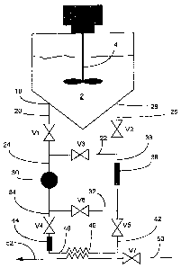
Fig. I is a schematic illustration of an automated, tempered combined in-
line/on-
line system according to one embodiment of the present invention;
Fig. 2 shows viscosity vs. temperature curves for two resins;
Fig. 3a is a side view of a sieve for use in the system according to the
invention;
Fig. 3b is a view from the outlet end of the sieve.
CA 02581850 2007-03-26
WO 2006/041372 PCT/SE2005/001338
3
Detailed Description of Preferred Embodiments
Fig. 1 shows a system comprising a batch reactor (reactor vessel) 2 in which a
manufacturing process of resin is carried out. Agitating means 4 driven by a
suitable
motor is provided in the reactor vessel.
At the bottom of reactor vessel 2, an outlet 18 is located to which a pipe
segment
20 is connected. A valve VI is mounted in pipe segment 20. Pipe segment 20 is
diverted
in two pathways by pipe segments 22 and 24 respectively. In pipe segment 22, a
valve
V3 is mounted, and a first loop formed by pipe segments 20 and 22 is completed
by a
further pipe segment 26, connected to inlet 28 at the bottom of reactor vessel
2, which
inlet is preferably not too close to outlet 18. In pipe segment 26, a valve V2
is mounted.
A means for circulating the sample, preferably a pump 30, for passing sample
medium through the system is provided in pipe segment 24. Segment 24 is
diverted in
two pathways by pipe segments 32 and 34. In segment 32 a valve V6 is provided.
Segment 32, 22, 24, and 36 complete a second loop. In segment 36, a
measurement box
38 is provided further described below. The side-loop formed by pipe segments
20, 24,
32, 36 and 26 forms an "in-line measurement loop".
A third loop is formed by pipe segments 20, 24, 34, 40, 42, 36, and 26. In
segment 34, a valve V4 and a sieve 44 are provided, the function and design of
which will
be further illustrated below. In segment 40, there is provided a heat
exchanger 46 for
tempering a passing sample to a desired temperature. Finally, a valve V5 is
provided in
the segment 42. The isolated or separated side-loop formed by pipe segments
22, 24, 34,
40, 42 and 36 will be referred to as an "on-line measurement loop".
Cooling medium may be passed through heat exchanger 46 via a suitable valve
V7 from inlet pipe 50 to outlet pipe 52.
Thus, there are two side-loops provided in the system illustrated in Fig. 1,
both
encompassing a common pump 30, and measurement box 38, namely the in-line loop
and the on-line loop. The first loop made up of pipe segments 20, 22, and 26
has no
function per se.
In an illustrated example below, the entire loop system has a capacity of
about
40 litres of sample, and is contemplated to be used with a reactor having a
volume of 50
m3. Thus, the sample constitutes about 0.08 % of the total reactor volume.
Examples of
suitable sensors for pH and viscosity measurements respectively are TBI-Bailey
(pH) and
BTG-Kalle (viscosity). Other suitable sensors may include e.g. a commercial
turbidity
sensor such as a Dual Beam Scattered-Light Sensor from Optek-Danulat, GmbH -
Essen, Germany as well as NIR spectroscopy equipment for collecting
spectrometrical
CA 02581850 2007-03-26
WO 2006/041372 PCT/SE2005/001338
4
.data from process media, e.g. an Interactance Immersion System 6500 from
FOSS. A
plate heat exchanger is suitably used to temper the process media. Measurement
box 38
suitably comprises an elongated tube, in which the sensor/sensors preferably
are
mounted to measure the temperature of the sample and preferably also to
monitor the
cooling capacity of the heat exchanger regulating the temperature of the
sample.
Variation in cooling capacity can thus be monitored and cleaning of the cooler
may be
made accordingly. Preferably, two sensors are mounted in either end of the
box. During
tempering, a volume change will occur, leading to pressure changes. Such
pressure/volume changes are preferably adjusted by keeping valve V1 open
during the
tempering phase. The compensators are essentially comprised of rubber elements
having the necessary flexibility. These compensators act to reduce vibrations
in the
measurement box, which is beneficial for the viscosity measurement in
particular. The
means for circulating the sample, preferably a pump, may be shut off when the
tempering
phase has been completed and the measurement of the process parameters is to
begin.
This is advantageous in the sense that the process parameters, e.g. the
viscosity, the pH,
conductivity, turbidity or spectrometrical data can be measured while the
sample is
standing still in the pipe segments. The sample flow may otherwise, if flowing
through the
measuring equipment, disturb the measurements and render them less accurate.
This
may be due to particles dissolved in the sample flow. The flow also may cause
turbulance, physical forces on the sensor. Further contaminants besides
particles, e.g.
bubbles, wood chips in certain production lines, can be wholly or partially
eliminated.
Particles and the like can also be eliminated by means of filter means as
further disclosed
herein.
The invention will be now be illustrated by an example. Let us assume an
application such as the manufacture of a urea formaldehyde resin. The process
could be
according to the following scheme:
1. loading of formaldehyde solution (50% w/w) and adjustment of the pH to 8.0-
8.6 using
sodium hydroxide in a suitable reactor.
2. loading of urea to a formaldehyde/urea (F/U) molar ratio of 2.0-2.2 and
control/adjustment of the pH to 8.0-8.6. Raising the temperature to 80 C and
allowing the
reaction to proceed for 10 minutes.
3. Adjusting the pH to 5.2-5.5 with formic acid and raising the temperature to
95 C
(exothermic reaction) and letting the condensation reaction proceed to a
viscosity of 400-
500 mPas.
4. Terminating the condensation reaction by increasing the pH to 8.0-8.6 and
adding urea
to a final molar ratio F/U of 1.0-1.2. Evaporation to a dry content of 65-70
wt%.
CA 02581850 2007-03-26
WO 2006/041372 PCT/SE2005/001338
5. Control of pH (8.0-8.6) and emptying the reactor.
As can be seen from this scheme above, a pH adjustment is carried out in the
beginning of the process (step 1). A pH determination is made again during
step 2 and
5 initially in step 3 after which the viscosity is measured. In order to get
high accuracy for
the viscosity, measurements should be made at 25 C, the process temperature in
the
reactor vessel during the condensation reaction being 90 C. In step 4, again
pH is
determined. Thus, this application requires measurements at two separate
temperatures,
and the switching between high and low temperature measurements should
preferably be
very rapid.
For the pH measurements (steps 1, 2 and 4), "in-line mode" is used. Thereby,
the in-line measurement loop defined by pipe segments 20, 24, 32, 36 and 26 is
established by opening valves V1, V2, V6, and closing valves V4, V5, and V3.
Pump 30
pumps process medium from reactor 2 through the in-line loop and the medium
will thus
pass through measurement box 38 where a pH meter is located. The medium is
pumped
through box 38 for a time sufficient for allowing the pH reading to stabilise.
Then the
reading is taken as an indication of the pH prevailing in the reactor.
The pH meter (not shown as such) is thus located inside measurement box 38.
Sometimes, glass material comprised in the measurement head of the pH meter is
affected by the process conditions, especially the composition of the process
medium,
and compensations for variations may be made by means of controlling software.
For the viscosity measurement (step 3), the "on-line mode" is used. Thereby
the on-line
measurement loop defined by pipe segments 22, 24, 34, 40, 42, and 36 is
established by
closing valves V1, V2 and V6, and opening valves V3, V4 and V5. In this mode,
the
process medium sample is pumped from the reactor into the above defined loop
to fill it
with the medium to be considered, and when the "on-line loop" defined above is
filled,
valves V1 and V2 are closed. Then the medium is circulated through the heat
exchanger
46. The heat exchanger is fed with a suitable cooling medium through inlet 50,
until the
temperature has reached a desired level. The flow of cooling medium may be
switched
off with valve V7. A temperature sensor (not shown) is also located inside
measurement
box 38. Of course, the pH may be continuously monitored during tempering if
desired.
As mentioned above, tempering is especially important for viscosity
measurements but also when measuring other temperature sensitive parameters.
At high
temperatures, the viscosity differs very little between different substances,
which fact is
evident from Fig. 2 showing viscosity vs. temperature for two different
resins. Clearly, the
difference is almost negligible at 100 C, whereas at room temperature
(approximately
CA 02581850 2007-03-26
WO 2006/041372 PCT/SE2005/001338
6
20 C), the difference is substantial. Thus, measurements at higher
temperatures require
extreme accuracy in the equipment to be used. Even if the equipment is
accurate, the
measurement is affected by various phenomena, e.g. vibrations, small solid
particles
present in the flow etc. These relatively small disturbances may still have a
very large
influence on the measurements. It has been found that only 1-5 minutes may be
required
before a reliable mesurement can be performed on a tempered sample which
enables
accurate monitoring. In the process example above, only in-line measurement
and on-line
tempering/measurement modes were discussed.
However, a number of other modes are operable for various purposes. Namely,
when a
viscosity measurement has been performed, a certain time has inevitably
lapsed, and the
process medium will have changed, In order to obtain a current value of the
viscosity, the
material locked inside the closed on-line loop must be replaced by a fresh
sample of
process medium. This will be referred to as the exchange phase of the on-line
function.
For this purpose, valve V3 is closed and valves V1 and V2 are opened, thereby
emptying
the loop through reactor vessel inlet 28 and pumping fresh sample into the
loop through
reactor vessel outlet 18. This exchange phase is terminated when the
temperature at the
inlet 28 equals the temperature at the outlet 18. During this exchange phase,
the heat
exchanger is preferably inoperative, i.e. valve V7 is switched off to prevent
cooling
medium to pass through the heat exchanger. At this time, i.e. when the inlet
and outlet
temperatures equal each other, the system is ready for another on-line mode
operation
(tempering/measuring).
In certain embodiments, such as when using a sensor with a relatively slow
equilibrating time (e.g. pH meter), it may be desirable to isolate a sample
flow without
tempering it in the heat exchanger. This may be done by closing valves VI, V2,
V4 and
V5, and opening valves V3 and V6. Thus, the sample is circulated through the
measurement box 38 for a time sufficient for the sensor in question to reach
an
equilibrium state. This function will be referred to as a"non-tempering
function".
It is possible to let the sample circulate without tempering for a period of
time
sufficient for a pH meter to equilibrate, while the remaining sample in the
now closed off
loop is stagnant, but will nevertheless continue to cool down to some extent.
Thus, when
the equilibrium pH measurement has successfully been made, the circulation in
the
tempering loop is restarted, and now the time to reach the desired temperature
will be
rather short, and a time saving has been achieved. It has been found that
switching from
the tempering function to the non-tempering function can be performed in only
about 15-
60 seconds which provides for very quick and efficient monitoring by measuring
parameters at both reactor temperature as well as tempered reactor samples.
CA 02581850 2007-03-26
WO 2006/041372 PCT/SE2005/001338
7
Also, it is of course necessary to clean the system at times between running
batches. For cleaning purposes there are a number of possible modes of
operation. Such
cleaning does not form part of the invention per se, and should in fact be
tailored for each
individual process set up, like an ordinary washing machine setting.
Since the varibus loops for the different measurement modes form sub-loops of
the entire side-loop system, and since they are inter-connected by means of a
number of
valves, it is possible to perform practically instantaneous switching between
the various
modes, simply by opening and closing appropriate valves. As a consequence, the
control
of a chemical process where a number of different parameters need to be
monitored
within short time frames is greatly simplified and made much more efficient.
Frequently, the process medium is contaminated by small particles, fibres and
other debris that has managed to pass the pump without having been comminuted
to a
sufficiently small size. The distance between the plates in the heat exchanger
is critical
(in the case of a plate heat exchanger). Preferably, the distance is commonly
about 4
mm, but may of course vary among different mariufacturers.
In order to prevent such debris from obstructing the.space between the plates,
a sieve
may be provided upstream the heat exchanger. This sieve is not necessary for
the
function of the system according to the invention, but is primarily provided
as a security
precaution. However, measurements of e.g. viscosity could be adversely
affected by the
presence of the mentioned objects in the flow, and thus the sieve may
nevertheless be
beneficial for the successful operation of the invention.
The sieve, shown in Figs. 3a and 3b, and generally designated 44 comprises an
elongated box 54 made of acid proof steel, and has a generally rectangular
cross section.
It is provided with an inlet 56 and an outlet 58, and is mounted in the pipe
segment 34
leading up to the heat exchanger 46 (see Fig. 1). A further inlet 60 for
rinsing purposes is
provided at an inclination, entering the box 54 from above. Inside sieve box
54 a mesh
structui-e 62 is provided. The mesh is arranged at an angle inside the box,
such that the
incoming liquid will pass mesh structure 62 from beneath. In this way, any
particles etc.
that will be caught by mesh structure 62, will settle onto the bottom surface
64 of box 54,
thus lowering the risk of clogging the mesh. The mesh structure 62 comprises a
mesh 66,
mounted in a thin acid proof frame structure (not shown in the figure). Inside
box 54,
there are provided two ridges 70 and 72 on each vertical wall 74 and 76 in box
54. The
ridges extend from the bottom of the box at the outlet end diagonally upwards
to the
upper part at the inlet end of the box, and thus, these pairs of ridges form a
respective
guide means in which the assembly of mesh and frame is inserted through an
opening 78
(indicated with dashed lines) at the outlet end of box 54.
CA 02581850 2007-03-26
WO 2006/041372 PCT/SE2005/001338
8
The opening is covered by a hood 79 that may be secured in a leak tight
fashion by
suitable fastening means and suitable gasket means. Thus, replacement of the
sieve
structure as a whole is not necessary, but it will suffice to replace mesh
structure 62,
which is an easy operation.
In the foregoing description, the invention has been described by example
where, inter
alia pH and viscosity have been the parameters of interest. The skilled man
will realise
that the principle underlying the invention may be used also for other
parameters in any
process wherein control of parameters is required in a tempered state, and
where rapid
switching between measurements made is required, without departing from the
inventive
concept as brought out in the appended claims.