Language selection

Search

Patent 2582146 Summary

Third-party information liability

Some of the information on this Web page has been provided by external sources. The Government of Canada is not responsible for the accuracy, reliability or currency of the information supplied by external sources. Users wishing to rely upon this information should consult directly with the source of the information. Content provided by external sources is not subject to official languages, privacy and accessibility requirements.

Claims and Abstract availability

Any discrepancies in the text and image of the Claims and Abstract are due to differing posting times. Text of the Claims and Abstract are posted:

  • At the time the application is open to public inspection;
  • At the time of issue of the patent (grant).
(12) Patent: (11) CA 2582146
(54) English Title: DEVICE FOR FASTENING A COVERING ON A CYLINDER OF A ROTARY PRESS
(54) French Title: DISPOSITIF DE FIXATION DE CAPOT D'UN CYLINDRE DE PRESSE ROTATIVE
Status: Expired and beyond the Period of Reversal
Bibliographic Data
(51) International Patent Classification (IPC):
  • B41F 27/06 (2006.01)
  • B41F 13/004 (2006.01)
(72) Inventors :
  • NAUMANN, REINHARD (Germany)
  • OERTEL, FRANK (Germany)
(73) Owners :
  • MANROLAND AG
(71) Applicants :
  • MANROLAND AG (Germany)
(74) Agent: NORTON ROSE FULBRIGHT CANADA LLP/S.E.N.C.R.L., S.R.L.
(74) Associate agent:
(45) Issued: 2010-02-16
(22) Filed Date: 2007-03-19
(41) Open to Public Inspection: 2007-09-17
Examination requested: 2007-03-19
Availability of licence: N/A
Dedicated to the Public: N/A
(25) Language of filing: English

Patent Cooperation Treaty (PCT): No

(30) Application Priority Data:
Application No. Country/Territory Date
10 2006 012 760.9 (Germany) 2006-03-17

Abstracts

English Abstract

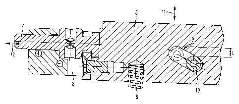
A printing cylinder having an axis-parallel channel in the cylinder, the channel narrowing toward the surface to form a slot for receiving the ends of a covering; a clamping member arranged in the channel and urged toward the slot by springs, the clamping member having at least one recess facing a respective at least one wall of the channel; and at least one supporting element arranged inside the channel and engaging a respective recess of the clamping member. A pair of adjusting elements arranged at the ends of the cylinder support the clamping member so that the clamping member can be radially displaced, the adjusting elements being arranged so that movement of the adjusting elements causes relative movement between the supporting element and the clamping member, whereby the clamping member is caused to move radially for clamping and unclamping the ends of the covering in the slot.


French Abstract

L'invention concerne un cylindre de presse qui comporte un canal intérieur parallèle à l'axe, lequel se rétrécit vers la surface pour former une fente destinée à recevoir les extrémités d'un capot; une bride de serrage disposée dans le canal et poussée vers la fente par des ressorts, la bride de serrage ayant au moins une échancrure faisant face à au moins une paroie respective du canal; et au moins un élément support disposé à l'intérieur du canal et en prise avec une échancrure respective de la bride de serrage. Une paire de pièces de réglage disposées aux extrémités du cylindre appuient la bride de serrage, de sorte que celle-ci puisse être déplacée radialement, les pièces de réglage étant disposées de sorte que leur mouvement entraîne un mouvement relatif entre l'élément support et la bride de serrage. Ainsi, la bride de serrage est forcée à se déplacer radialement pour serrer et déserrer les extrémités du capot dans la fente.

Claims

Note: Claims are shown in the official language in which they were submitted.


CLAIMS
1. Device for fastening a covering (1) on a cylinder (2) of a rotary printing
press with
at least one axially parallel channel (3) in the cylinder (2), which forms a
slot (4) for inserting
and removing the ends of a covering (1), and with a clamping member (5), which
is arranged
in the channel (3) and is pressed radially in the direction of the slot (4) by
means of several
compression springs (6) for fastening the covering (1), wherein adjusting
elements (7), by
which the clamping member (5) is supported in a way that allows it to be
radially displaced,
are arranged at the ends of the cylinder (2) to allow the ends of the covering
(1) to be inserted
or removed, characterized by the fact that at least one supporting element (8)
is arranged
inside the channel (3) along with the clamping member (5) and engages at least
one recess (9)
in the clamping member (5), such that movement of the adjusting elements (7)
causes relative
movement between the supporting element (8) and the clamping member (5).
2. Device in accordance with Claim 1, characterized by the fact that at least
one
positioning element (13) is present, which prevents axial movement of the
clamping member
(5) but allows radial movement of the clamping member (5).
3. Device in accordance with Claim 2, characterized by the fact that the one
or more
positioning elements (13) are displaceably mounted in a slot (14).
4. Device in accordance with Claim 1, characterized by the fact that, in
addition to
the clamping member (5), at least one supporting element (8) is present, such
that the
supporting elements (8) are joined with one another through the recess (9) in
the clamping
member (5) by means of a pin (10).
5. Device in accordance with Claim 4, characterized by the fact that several
recesses
(9) and several supporting elements (8) are located along the longitudinal
axis of the
7

clamping member (5).
6. Device in accordance with Claim 4, characterized by the fact that the
recess is
formed as a slot (9), which is inclined relative to the axis of rotation of
the cylinder.
7. Device in accordance with Claim 1, characterized by the fact that the
adjusting
elements (7) are designed to be adjusted in the radial and/or axial direction
(12) of the
cylinder (2).
8. Device in accordance with Claim 7, characterized by the fact that a power
transmission system is arranged between the adjusting element (7) and clamping
member (5)
and/or between the adjusting element (7) and supporting element (8).
9. Device in accordance with Claim 7, characterized by the fact that at least
one drive
is installed for moving the adjusting elements (7).
10. Device in accordance with Claim 8, characterized by the fact that the
drive is a
pneumatic and/or hydraulic and/or electric drive.
11. Device in accordance with Claim 8, wherein the power transmission system
is one
of a guide block and a lever.
8

Description

Note: Descriptions are shown in the official language in which they were submitted.


CA 02582146 2007-03-19
DEVICE FOR FASTENING A COVERING ON A CYLINDER OF A ROTARY PRESS
BACKGROUND OF THE INVENTION
1. Field of the Invention
[0001] The invention concerns a device for fastening a covering on a cylinder
of a
rotary printing press including at least one axially parallel channel in the
cylinder, the channel
forming a slot into which the ends of a covering can be inserted and removed,
and a clamping
member, which is arranged in the channel and is pressed radially toward the
slot by means of
several compression springs for fastening the covering, wherein adjusting
elements, by
which the clamping member is supported in a way that allows it to be radially
displaced, are
arranged at the ends of the cylinder.
2. Description of the Related Art
[0002] DE 197 03 290 Al discloses a device for fastening a covering on an
impression cylinder of a rotary press. In this known device, a clamping member
within an
axially parallel channel of the cylinder body is pressed by compression
springs radially
outward against the walls of the channel to fix a covering between the channel
walls and the
clamping member. To clamp and unclamp the covering, the clamping member is
adjusted
radially towards the inside of the cylinder by setscrews located at its outer
ends. In this
clamped and unclamped position, the compression springs cause a deflection of
the clamping
rail towards the outside of the cylinder between the setscrews located at the
ends.
[0003] Precisely in the case of narrow cylinders, such as one plate-around,
double-
width impression cylinders, the size or the diameter of the channel bore is
limited. Due to the
limited channel diameter, the size of the clamping rail and thus its stiffness
are limited
1

CA 02582146 2007-03-19
accordingly. If the clamping member is adjusted radially towards the inside of
the cylinder
by setscrews located at its outer ends for the purpose of clamping or bracing
the covering, the
convexity of the deflected clamping rail in the center region of the cylinder
can project so
close to the channel wall that the covering cannot be released or inserted.
SUMMARY OF THE INVENTION
[0004] Therefore, an object of the invention is to provide a device for
fastening a
covering on a cylinder of a rotary press in such a way that deflection of the
clamping rail
during release of the clamping is avoided.
[0005] The inventors realized that it is possible to prevent the deflection of
the
clamping rail during the clamping or the unclamping of a covering if, in
addition to the
clamping rail, supporting elements are arranged in the lockup channel in such
a way that the
supporting elements act as a mechanical barrier to the deflection of the
clamping rail, and at
the same time the force resulting from the deflection is diverted towards the
inside wall of the
channel by the supporting elements.
[0006] According to the invention, at least one supporting element is arranged
inside
the channel along with the clamping member. This supporting element engages in
at least one
recess in the clamping member, so that the movement of the adjusting elements
causes
relative movement between the supporting element and the clamping member.
[0007] In this design of the device for fastening a covering on a cylinder, if
the
supporting element is displaced by the adjusting element in the direction of
the channel bore,
then this displacement movement leads to relative movement between the
clamping member
and the supporting element in the radial direction of the channel bore when
the recess is
suitably designed, e.g., an oblong hole. The supporting element is pressed
against the wall of
2

CA 02582146 2009-07-08
the channel bore and causes the clamping member to be lowered from the fixed
position of
the covering. Deflection of the clamping member is prevented by the support of
the
supporting element in the channel bore.
In accordance with a broad aspect, there is provided a Device for fastening a
covering
on a cylinder of a rotary printing press with at least one axially parallel
channel in the
cylinder, which forms a slot for inserting and removing the ends of a
covering, and with a
clamping member, which is arranged in the channel and is pressed radially in
the direction of
the slot by means of several compression springs for fastening the covering,
wherein
adjusting elements, by which the clamping member is supported in a way that
allows it to be
radially displaced, are arranged at the ends of the cylinder to allow the ends
of the covering to
be inserted or removed, characterized by the fact that at least one supporting
element is
arranged inside the channel along with the clamping member and engages at
least one recess
in the clamping member, such that movement of the adjusting elements causes
relative
movement between the supporting element and the clamping member.
Other objects and features of the present invention will become apparent from
the
following detailed description considered in conjunction with the accompanying
drawings. It
is to be understood, however, that the drawings are designed solely for
purposes of
illustration and not as a definition of the limits of the invention, for which
reference should be
made to the appended claims. It should be further understood that the drawings
are not
necessarily drawn to scale and that, unless otherwise indicated, they are
merely intended to
conceptually illustrate the structures and procedures described herein.
BRIEF DESCRIPTION OF THE DRAWINGS
[0008] Figure 1 shows a cross-sectional view of a segment of a cylinder with
the new
clamping device;
3

CA 02582146 2009-07-08
[0008] Figure la shows a cross section through a positioning pin and clamping
member;
[0008] Figure 2 shows a cross-sectional view of another design of the new
clamping
device;
[0008] Figure 3 shows a detail top view of a clamping member with slot and
adjusting
element; and
[0008] Figure 4 shows a cross-sectional view through a clamping member with
supporting element and pin through the plane of the slot.
3a

CA 02582146 2007-03-19
DETAILED DESCRIPTION OF THE PRESENTLY PREFERRED EMBODIMENTS
[0013] The present invention is described below with reference to Figures 1 to
4.
[0014] Figure 1 shows a segment of a cylinder 2 with a new clamping device of
the
invention in a vertical cross-sectional view through the axis of rotation of
the cylinder. The
cylinder 2 can be either a plate cylinder, which carries one or more printing
plates, or a
transfer cylinder, which carries one or more rubber blankets on the surface of
the cylinder as
a packing or as a covering 1. So that the ends of the covering 1 can be
fastened to the
cylinder 2, a lockup channel 3 extending in the axial direction is formed in
the cylinder 2
between support plates 15, 16 which form part of the cylinder. The lockup
channel 3 forms a
slot 4 in the surface of the cylinder, and the covering I is inserted in or
removed from this slot
4. The ends of the covering I can be clamped between the inside wall of the
channel and the
clamping member 5 by means of spring elements (not shown). The clamping member
5 is
movably supported in the radial direction I 1 for clamping or unclamping the
covering 1. The
clamping member 5 can be displaced in the direction of the channel by an
adjusting element
7, here a pin or a setscrew, which can be moved parallel to the axis of
rotation of the cylinder.
This results in movement of the clamping member 5 relative to the supporting
elements (not
shown). In this connection, a positioning pin 13, which is movably supported
in an oblong
hole 14, can make it possible for the clamping member 5 to move only in the
radial direction
11 of the cylinder.
[0015] Figure 1 a shows a cross section through the positioning pin 13 and the
clamping member 5. The positioning pin 13 is supported in oblong 14, so that
only radial
movement i 1 of the clamping member 5 is permitted, and axial movement in the
direction of
the channel is prevented.
4

CA 02582146 2007-03-19
[0016] Figure 2 shows a cross-sectional view through the lockup channel 3,
which is
formed as a bore, and another design of the new clamping device. The covering
1 is a
blanket positioned on a carrier plate. The two ends of the carrier plate are
pressed against the
inside wall of the channel by the clamping member 5, so that the blanket is
clamped to the
circumference of the cylinder 2. In this connection, the clamping member 5 is
pressed from
the base of the lockup channel 3 in the direction of the slot 4 by means of
compression
springs 6. The clamping member 5 has two sidepieces that run conically in the
direction of
the slot 4, and the two ends of the carrier plate in Figure 2 are clamped on
the upper side.
Supporting elements 8, which are joined with one another by joining elements
and recesses
(not shown) in the clamping member 5, are mounted in the lockup channel 3
above and
below the clamping member 5. If the clamping member 5 is moved in the
direction of the
channel bore by an adjusting element (not shown), then this adjusting movement
results in
relative movement between the clamping member 5 and the supporting element 8
in the
radial direction 11 of the channel bore, if the recess is suitably designed,
e.g., as an oblong
hole. The supporting element is pressed against the wall of the channel bore
and causes the
clamping member to be lowered from the fixed position of the covering 1.
Deflection of the
clamping member 5 is prevented by the support of the supporting element 8 in
the channel
bore.
[0017] Figure 3 shows a top view of a segment of a clamping member 5 in the
longitudinal direction of the lockup channel. A pin-like adjusting element 7
is threaded and
can be moved in direction 12, in this case, parallel to the axis of the
cylinder. In this
embodiment, the clamping member 5 has an oblong hole 9 with an oblique
inclination. The
supporting elements 8 (shown only partially) are joined with one another
through the oblong
hole 9 by means of a pin 10. When the adjusting element 7 is then moved to the
right, the
5

CA 02582146 2007-03-19
supporting elements 8 are pressed against the wall of the channel bore, and
the clamping
member 5 is lowered by the vertical distance h, so that the slot on the
cylinder is released for
clamping or unciamping. In the lowered state, the pin would be in the upper
position of the
oblong hole 9 (indicated by broken lines). The positioning pin described in
connection with
Figure 1 a allows only radial movement 11 of the clamping member 5, whereas
the supporting
elements 8 can be displaced axially within the channel bore 3.
[0018] Figure 4 shows a cross-sectional view through a clamping member 5 with
supporting elements 8 and pin 10 through the plane of the hole 9.
[0019] It is understood that the aforementioned features and the features
specified in
the claims can be used not only in the particular combinations that have been
specified but
also in other combinations or by themselves without exceeding the scope of the
invention.
[0020] Thus, while there have shown and described and pointed out fundamental
novel features of the invention as applied to a preferred embodiment thereof,
it will be
understood that various omissions and substitutions and changes in the form
and details of the
devices illustrated, and in their operation, may be made by those skilled in
the art without
departing from the spirit of the invention. For example, it is expressly
intended that all
combinations of those elements and/or method steps which perform substantially
the same
function in substantially the same way to achieve the same results are within
the scope of the
invention. Moreover, it should be recognized that structures and/or elements
and/or method
steps shown and/or described in connection with any disclosed form or
embodiment of the
invention may be incorporated in any other disclosed or described or suggested
form or
embodiment as a general matter of design choice. It is the intention,
therefore, to be limited
only as indicated by the scope of the claims appended hereto.
6

Representative Drawing
A single figure which represents the drawing illustrating the invention.
Administrative Status

2024-08-01:As part of the Next Generation Patents (NGP) transition, the Canadian Patents Database (CPD) now contains a more detailed Event History, which replicates the Event Log of our new back-office solution.

Please note that "Inactive:" events refers to events no longer in use in our new back-office solution.

For a clearer understanding of the status of the application/patent presented on this page, the site Disclaimer , as well as the definitions for Patent , Event History , Maintenance Fee  and Payment History  should be consulted.

Event History

Description Date
Time Limit for Reversal Expired 2013-03-19
Letter Sent 2012-03-19
Grant by Issuance 2010-02-16
Inactive: Cover page published 2010-02-15
Inactive: Final fee received 2009-12-04
Pre-grant 2009-12-04
Notice of Allowance is Issued 2009-10-22
Letter Sent 2009-10-22
Notice of Allowance is Issued 2009-10-22
Inactive: Approved for allowance (AFA) 2009-10-20
Amendment Received - Voluntary Amendment 2009-07-08
Inactive: S.30(2) Rules - Examiner requisition 2009-03-03
Letter Sent 2008-10-28
Application Published (Open to Public Inspection) 2007-09-17
Inactive: Cover page published 2007-09-16
Inactive: First IPC assigned 2007-08-17
Inactive: IPC assigned 2007-08-17
Letter Sent 2007-07-05
Inactive: Single transfer 2007-05-15
Inactive: Courtesy letter - Evidence 2007-04-24
Inactive: Filing certificate - RFE (English) 2007-04-20
Letter Sent 2007-04-20
Application Received - Regular National 2007-04-20
All Requirements for Examination Determined Compliant 2007-03-19
Request for Examination Requirements Determined Compliant 2007-03-19

Abandonment History

There is no abandonment history.

Maintenance Fee

The last payment was received on 2009-02-19

Note : If the full payment has not been received on or before the date indicated, a further fee may be required which may be one of the following

  • the reinstatement fee;
  • the late payment fee; or
  • additional fee to reverse deemed expiry.

Patent fees are adjusted on the 1st of January every year. The amounts above are the current amounts if received by December 31 of the current year.
Please refer to the CIPO Patent Fees web page to see all current fee amounts.

Fee History

Fee Type Anniversary Year Due Date Paid Date
Application fee - standard 2007-03-19
Request for examination - standard 2007-03-19
Registration of a document 2007-05-15
Registration of a document 2008-07-11
MF (application, 2nd anniv.) - standard 02 2009-03-19 2009-02-19
Final fee - standard 2009-12-04
MF (patent, 3rd anniv.) - standard 2010-03-19 2010-02-23
MF (patent, 4th anniv.) - standard 2011-03-21 2011-03-03
Owners on Record

Note: Records showing the ownership history in alphabetical order.

Current Owners on Record
MANROLAND AG
Past Owners on Record
FRANK OERTEL
REINHARD NAUMANN
Past Owners that do not appear in the "Owners on Record" listing will appear in other documentation within the application.
Documents

To view selected files, please enter reCAPTCHA code :


To view images, click a link in the Document Description column. To download the documents, select one or more checkboxes in the first column and then click the "Download Selected in PDF format (Zip Archive)" or the "Download Selected as Single PDF" button.

List of published and non-published patent-specific documents on the CPD .

If you have any difficulty accessing content, you can call the Client Service Centre at 1-866-997-1936 or send them an e-mail at CIPO Client Service Centre.


Document
Description 
Date
(yyyy-mm-dd) 
Number of pages   Size of Image (KB) 
Abstract 2007-03-18 1 23
Drawings 2007-03-18 5 91
Description 2007-03-18 6 265
Claims 2007-03-18 2 70
Representative drawing 2007-08-22 1 18
Description 2009-07-07 7 286
Claims 2009-07-07 2 65
Drawings 2009-07-07 5 74
Representative drawing 2010-01-25 1 16
Acknowledgement of Request for Examination 2007-04-19 1 176
Filing Certificate (English) 2007-04-19 1 158
Courtesy - Certificate of registration (related document(s)) 2007-07-04 1 107
Reminder of maintenance fee due 2008-11-19 1 112
Commissioner's Notice - Application Found Allowable 2009-10-21 1 162
Maintenance Fee Notice 2012-04-29 1 171
Correspondence 2007-04-19 1 27
Correspondence 2009-12-03 2 69