Language selection

Search

Patent 2582251 Summary

Third-party information liability

Some of the information on this Web page has been provided by external sources. The Government of Canada is not responsible for the accuracy, reliability or currency of the information supplied by external sources. Users wishing to rely upon this information should consult directly with the source of the information. Content provided by external sources is not subject to official languages, privacy and accessibility requirements.

Claims and Abstract availability

Any discrepancies in the text and image of the Claims and Abstract are due to differing posting times. Text of the Claims and Abstract are posted:

  • At the time the application is open to public inspection;
  • At the time of issue of the patent (grant).
(12) Patent Application: (11) CA 2582251
(54) English Title: THERMAL RELEASE
(54) French Title: DECLENCHEUR THERMIQUE
Status: Deemed Abandoned and Beyond the Period of Reinstatement - Pending Response to Notice of Disregarded Communication
Bibliographic Data
(51) International Patent Classification (IPC):
  • H01H 71/16 (2006.01)
(72) Inventors :
  • NEUBAUER, THOMAS (Austria)
(73) Owners :
  • ABB PATENT GMBH
(71) Applicants :
  • ABB PATENT GMBH (Germany)
(74) Agent: MARKS & CLERK
(74) Associate agent:
(45) Issued:
(86) PCT Filing Date: 2005-10-06
(87) Open to Public Inspection: 2006-05-18
Examination requested: 2010-06-16
Availability of licence: N/A
Dedicated to the Public: N/A
(25) Language of filing: English

Patent Cooperation Treaty (PCT): Yes
(86) PCT Filing Number: PCT/EP2005/010748
(87) International Publication Number: WO 2006050775
(85) National Entry: 2007-03-29

(30) Application Priority Data:
Application No. Country/Territory Date
10 2004 054 176.0 (Germany) 2004-11-10

Abstracts

English Abstract


The invention relates to a thermal tripping device which is heated indirectly
by means of a heating winding (10) and which comprises a release strip made of
thermostatic bimetal (30), a form memory alloy or similar. An insulating
intermediate layer (31) is arranged between the heating winding and the
release strip and one of the ends of the heating winding is connected to a
supply conductor. The heating winding is embodied in an identically meandering
manner for all current intensities and is folded about the insulating
intermediate layer. In order to modify the resistance of the heating winding
for other current intensities, the discharge (34) is connected to a wiring
point between the ends of the heating windings.


French Abstract

L'invention concerne un déclencheur thermique de surintensité chauffé indirectement au moyen d'un enroulement chauffant (10), ce déclencheur comprenant une lame de déclenchement réalisée dans un matériau thermique bimétallique (30), un alliage à mémoire de forme ou similaire. Une couche intermédiaire isolante (31) est placée entre l'enroulement chauffant et la lame de déclenchement et une des extrémités de l'enroulement chauffant est reliée à un conducteur d'alimentation. L'enroulement chauffant se présente en forme de méandre de façon identique pour toutes les intensités de courant et il est plié autour de la couche intermédiaire isolante. Pour modifier la résistance de l'enroulement chauffant pour d'autres intensités de courant, la dérivation (34) est raccordée à un point de prise entre les extrémités de l'enroulement chauffant.

Claims

Note: Claims are shown in the official language in which they were submitted.

-7-
claims
1. A thermal overcurrent release, which is heated
indirectly by means of a heating winding, having a
tripping strip consisting of a bimetallic strip, a
shape memory alloy or the like, an intermediate
insulating layer being inserted between the heating
winding and the tripping strip, and one of the ends of
the heating winding being connected to a feed
conductor, characterized in that the heating winding
has an identical, meandering design for all current
levels and is folded around the intermediate insulating
layer, and in that, in order to change the resistance
of the heating winding for other current levels, the
outgoing line is connected to a tapping point between
the ends of the heating winding.
2. A thermal overcurrent release, which is heated
indirectly by means of a heating winding, having a
tripping strip consisting of a bimetallic strip, a
shape memory alloy or the like, an intermediate
insulating layer being inserted between the heating
winding and the tripping strip, and one of the ends of
the heating winding being connected to a feed
conductor, characterized in that the heating winding
has an identical, meandering design for all current
levels and is folded around the intermediate insulating
layer, and in that, in order to carry out the change,
the outgoing line is connected to the other end of the
heating winding, and at least two adjacent turns are
short-circuited.
3. The release as claimed in claim 2, characterized
in that the adjacent turns are short-circuited by a
welded joint and/or by means of a conductor section.

Description

Note: Descriptions are shown in the official language in which they were submitted.


CA 02582251 2007-03-29
-1-
Thermal release
Description
The invention relates to a tripping strip, which is
heated indirectly by means of a heating winding, in
accordance with the precharacterizing clause of
claim 1.
Tripping strips which are either heated directly or
heated indirectly and are produced from a bimetallic
strip or from a shape alloy are used as thermal
releases for an electrical service switching device,
for example a line circuit breaker, motor circuit
breaker, etc. In the case of direct tripping, the
tripping strip has the current flowing through it,
while, in the case of indirect heating, a heating
winding is arranged around the tripping strip, which
heating winding has current flowing.through it and has
a specific nonreactive resistance, which is sufficient
for heating the tripping strip such that it bends out
and permanently opens a latching point in the service
switching device. The tripping strip generally does not
have current flowing through it.
These releases are generally used for so-called
overcurrents, i.e. for currents which are not
short-circuit currents and which can flow through the
service switching device for a certain amount of time
before they need to be switched off.
The invention is concerned with an indirectly heated
tripping strip.
Such indirectly heated tripping strips are known in
large numbers. Insulation which is in the form of, for
example, a glass-fiber bush is wound around the
tripping strip itself, i.e. around the bimetallic strip
(in this case strips of shape alloy are naturally

CA 02582251 2007-03-29
- 2 -
included) . A resistance wire in the form of a round
wire or a flat wire is wound around this insulating
body or around this insulation, it being possible for
one of the ends of the winding to be fixed to the
bimetallic strip, while the other end of the winding is
connected to an incoming line by means of a braided
wire. In this case, the bimetallic strip would be fixed
at the end at which the winding is fixed to a fixing
point in the switching device.
In another refinement, the incoming power line can be
connected at one end of the winding and the outgoing
power line can be connected at the other end.
These windings are produced manually, in which case it
would also be necessary for different winding shapes to
be provided owing to different current levels and
different tripping times. Owing to this high degree of
variance, there is a great deal of outlay on
positioning and mounting and, furthermore, the
manufacturing quality fluctuates owing to the high
proportion of manual working steps.
The object of the invention is to provide a thermal
release which provides a uniform geometry of the
heating winding for all tripping requirements.
This object is achieved according to the invention by
the features of claim 1.
Accordingly, the heating winding has an identical,
meandering design for all current levels and is folded
around the intermediate insulating layer and, in order
to change the resistance of the heating winding for
other current levels, i.e. in order to match the
tripping strip to different tripping tasks, the
outgoing line is connected to a tapping point between
the ends of the heating winding.

CA 02582251 2007-03-29
- 3 -
Depending on the distance between the tapping point and
the connection of the incoming line, different
resistances of the winding and therefore different
response values for the release can be set, in which
case the winding as such is the same for all of these
requirements.
This meandering heating winding is produced in a simple
manner owing to the fact that a high-resistivity
sheet-metal material is stamped; the meandering shape
is then folded around the intermediate insulating
layer.
In accordance with one further embodiment of the
invention, in order to change the heating winding for
other current levels, the outgoing line can be
connected to the other end of the heating winding, in
which case at least two adjacent turns are
short-circuited.
These short circuits can either be performed by means
of a conductor section or by means of a welded joint.
Further advantageous refinements of the invention are
described in the further dependent claims.
The invention and further advantageous refinements and
improvements of the invention will be explained and
described in more detail with reference to the drawing,
in which a few exemplary embodiments of the invention
are illustrated and in which:
figure 1 shows a plan view of a heating winding
having a meandering shape after the
stamping process,

CA 02582251 2007-03-29
- 4 -
figure 2 shows a sectional view along the section
line II-II in figizre 3, and
figures 3 to 6 show different refinements of the
invention.
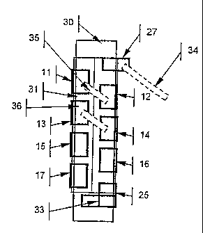
A heating winding 10 is stamped, with a meandering
shape, from a high-resistivity material in the form of
a metal sheet, the heating winding 10 having a
plurality of first longitudinal webs 11, 13, 15, 17 and
second longitudinal webs 12, 14, 16, which are each
positioned in a line, which two lines, denoted by L1
and L2, run parallel to one another. A transverse web
18, which runs at right angles to the lines Ll, L2,
adjoins one end of the longitudinal web 11, and one end
of the longitudinal web 13, which is adjacent to the
longitudinal web 11, adjoins the other end of the
longitudinal web 12 via a transverse web 19. In this
manner, the longitudinal webs 13 and 14, 14 and 15, 15
and 16, 16 and 17 are alternately connected to one
another by transverse webs 20, 21, 22, 23; a further
transverse web 24 adjoins the free end of the
longitudinal web 17 and bears a lug 25, which runs in
the longitudinal direction of the line L2 and to which
a conductor can be connected. In a corresponding
manner, a lug 27 is arranged on a third transverse web
26, to which lug a further conductor can be connected;
the incoming conductor could be connected to the lug
25, for example, and the outgoing conductor of the
heating winding could be connected to the lug 27.
This heating winding is folded around a bimetallic
strip 30, as illustrated in figure 2. An intermediate
insulating layer 31 in the form of an insulating bush
is laid around the bimetallic strip 30 and is produced,
for example, from a glass-fiber material. The
longitudinal webs 11, 13, 15 and 17 and 12, 14, 16 are
folded around this intermediate insulating layer 31

CA 02582251 2007-03-29
- 5 -
such that the outer (in figure 1) edges of the
longitudinal webs now rest on the flat side 32 of the
intermediate insulating layer 31.
Figure 4 shows a plan view in accordance with the arrow
direction A. The intermediate insulating layer 31 is
wound around the bimetallic strip 30, and the
longitudinal webs 11, 13, 15, 17 and the longitudinal
webs 12, 14, 16, together with the tab, are located on
the flat side 32 of the insulating layer.
This arrangement of the heating winding is identical
for all tripping tasks in question. The incoming line
33 is illustrated by an arrow P and is terminated at
the lug 25, whereas the outgoing line 34 is connected
to the lug 27 and is in this case in the form of a
braided wire.
In order to match this thermal release to the
corresponding tripping tasks, the longitudinal webs 11
and 12 are connected to a connecting conductor section
35, and the longitudinal webs 13 and 14 are connected
to a further conductor section 36. In addition, the
sections 15 and 16 could also be connected to a
conductor section. The transverse webs 18 and 20 are
short-circuited by the conductor sections 35 and 36,
with the result that the current no longer flows via
the transverse webs 18 and 20, as a result of which the
total resistance of the heating wire is altered.
Figure 5 shows a further refinement of the invention;
therein, the two longitudinal webs 11 and 12 are
connected to one another by means a welded joint 40;
also illustrated is a welded joint 41 between the
longitudinal webs 12 and 14, as a result of which the
two transverse webs 19 and 20 and the longitudinal web
13 are disconnected from the heating winding. It is
naturally also possible for three longitudinal webs to

CA 02582251 2007-03-29
- 6 -
be connected to one another, namely the longitudinal
webs 15, 16 and 14, as illustrated, by means of the
welded joint 41a, as a result of which a corresponding
change to the resistance of the heating winding is
likewise brought about.
Figure 3 shows a further embodiment of the invention.
In this case, connection tabs or projections 45 and 46
are integrally formed on the longitudinal webs 12 and
14, with the result that the incoming line is
connected, for example, to the longitudinal web 14, as
a result of which only the longitudinal webs 11, 12 and
13 are connected into the current flow.
Instead of providing protrusions 45 and 46, the
individual feed conductors 33 can either be connected
to the longitudinal web 11 or to the longitudinal web
15 or to the longitudinal web 16.

Representative Drawing
A single figure which represents the drawing illustrating the invention.
Administrative Status

2024-08-01:As part of the Next Generation Patents (NGP) transition, the Canadian Patents Database (CPD) now contains a more detailed Event History, which replicates the Event Log of our new back-office solution.

Please note that "Inactive:" events refers to events no longer in use in our new back-office solution.

For a clearer understanding of the status of the application/patent presented on this page, the site Disclaimer , as well as the definitions for Patent , Event History , Maintenance Fee  and Payment History  should be consulted.

Event History

Description Date
Time Limit for Reversal Expired 2012-10-09
Application Not Reinstated by Deadline 2012-10-09
Deemed Abandoned - Failure to Respond to Maintenance Fee Notice 2011-10-06
Inactive: Abandoned - No reply to s.30(2) Rules requisition 2011-09-19
Inactive: S.30(2) Rules - Examiner requisition 2011-03-18
Amendment Received - Voluntary Amendment 2011-01-17
Letter Sent 2010-06-23
Request for Examination Received 2010-06-16
All Requirements for Examination Determined Compliant 2010-06-16
Request for Examination Requirements Determined Compliant 2010-06-16
Letter Sent 2007-09-06
Inactive: Single transfer 2007-07-04
Inactive: Cover page published 2007-06-01
Inactive: Courtesy letter - Evidence 2007-05-29
Inactive: Notice - National entry - No RFE 2007-05-25
Inactive: First IPC assigned 2007-04-24
Application Received - PCT 2007-04-23
National Entry Requirements Determined Compliant 2007-03-29
Application Published (Open to Public Inspection) 2006-05-18

Abandonment History

Abandonment Date Reason Reinstatement Date
2011-10-06

Maintenance Fee

The last payment was received on 2010-09-24

Note : If the full payment has not been received on or before the date indicated, a further fee may be required which may be one of the following

  • the reinstatement fee;
  • the late payment fee; or
  • additional fee to reverse deemed expiry.

Please refer to the CIPO Patent Fees web page to see all current fee amounts.

Fee History

Fee Type Anniversary Year Due Date Paid Date
Basic national fee - standard 2007-03-29
MF (application, 2nd anniv.) - standard 02 2007-10-09 2007-03-29
Registration of a document 2007-07-04
MF (application, 3rd anniv.) - standard 03 2008-10-06 2008-09-25
MF (application, 4th anniv.) - standard 04 2009-10-06 2009-09-25
Request for examination - standard 2010-06-16
MF (application, 5th anniv.) - standard 05 2010-10-06 2010-09-24
Owners on Record

Note: Records showing the ownership history in alphabetical order.

Current Owners on Record
ABB PATENT GMBH
Past Owners on Record
THOMAS NEUBAUER
Past Owners that do not appear in the "Owners on Record" listing will appear in other documentation within the application.
Documents

To view selected files, please enter reCAPTCHA code :


To view images, click a link in the Document Description column. To download the documents, select one or more checkboxes in the first column and then click the "Download Selected in PDF format (Zip Archive)" or the "Download Selected as Single PDF" button.

List of published and non-published patent-specific documents on the CPD .

If you have any difficulty accessing content, you can call the Client Service Centre at 1-866-997-1936 or send them an e-mail at CIPO Client Service Centre.


Document
Description 
Date
(yyyy-mm-dd) 
Number of pages   Size of Image (KB) 
Description 2007-03-29 6 225
Claims 2007-03-29 1 43
Abstract 2007-03-29 1 77
Drawings 2007-03-29 1 27
Representative drawing 2007-06-01 1 7
Cover Page 2007-06-01 1 37
Notice of National Entry 2007-05-25 1 195
Courtesy - Certificate of registration (related document(s)) 2007-09-06 1 129
Reminder - Request for Examination 2010-06-08 1 129
Acknowledgement of Request for Examination 2010-06-23 1 177
Courtesy - Abandonment Letter (Maintenance Fee) 2011-12-01 1 173
Courtesy - Abandonment Letter (R30(2)) 2011-12-12 1 166
PCT 2007-03-29 3 166
Correspondence 2007-05-25 1 25