Language selection

Search

Patent 2582259 Summary

Third-party information liability

Some of the information on this Web page has been provided by external sources. The Government of Canada is not responsible for the accuracy, reliability or currency of the information supplied by external sources. Users wishing to rely upon this information should consult directly with the source of the information. Content provided by external sources is not subject to official languages, privacy and accessibility requirements.

Claims and Abstract availability

Any discrepancies in the text and image of the Claims and Abstract are due to differing posting times. Text of the Claims and Abstract are posted:

  • At the time the application is open to public inspection;
  • At the time of issue of the patent (grant).
(12) Patent Application: (11) CA 2582259
(54) English Title: CHILD-RESISTANT SQUEEZE-AND-TURN CLOSURE AND CONTAINER PACKAGE
(54) French Title: FERMETURE DE PROTECTION DE TYPE PRESSER-ET-TOURNER ET EMBALLAGE RECIPIENT SECURISES VIS-A-VIS DES ENFANTS
Status: Deemed Abandoned and Beyond the Period of Reinstatement - Pending Response to Notice of Disregarded Communication
Bibliographic Data
(51) International Patent Classification (IPC):
  • B65D 50/04 (2006.01)
(72) Inventors :
  • ROBINSON, PHILIP J. (United States of America)
(73) Owners :
  • REXAM CLOSURE SYSTEMS INC.
(71) Applicants :
  • REXAM CLOSURE SYSTEMS INC. (United States of America)
(74) Agent: GOWLING WLG (CANADA) LLP
(74) Associate agent:
(45) Issued:
(86) PCT Filing Date: 2005-07-14
(87) Open to Public Inspection: 2006-04-27
Examination requested: 2010-05-13
Availability of licence: N/A
Dedicated to the Public: N/A
(25) Language of filing: English

Patent Cooperation Treaty (PCT): Yes
(86) PCT Filing Number: PCT/US2005/025057
(87) International Publication Number: US2005025057
(85) National Entry: 2007-03-28

(30) Application Priority Data:
Application No. Country/Territory Date
10/965,553 (United States of America) 2004-10-13

Abstracts

English Abstract


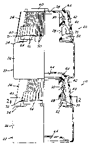
A child-resistant package includes a container (22) having a finish (28) with
at least one external thread (30), at least one axial lug (32) on a shoulder
(34) spaced from the thread and an external abutment (70) on the finish
adjacent to the lug. A closure (24) of integrally molded plastic construction
includes a base wall (38), a peripheral outer wall (40), and an inner wall
(42) spaced from the outer wall and having at least one internal thread for
securement to the container finish. The outer wall has diametrically opposed
gaps (46, 48), and the inner wall extends axially in radial alignment with the
gaps for circumferential abutment with the at least one lug on the container.
The inner wall is flexible inwardly for clearing the lug between the lug and
the external abutment, and for permitting removal of the closure from the
container finish. The external abutment (70) preferably is in the form of an
external bead that extends circumferentially around the finish in alignment
with an edge of the lug.


French Abstract

Un emballage sécurisé vis-à-vis des enfants comprend un récipient (22) ayant une terminaison (28) avec au moins un filetage extérieur (30), au moins une saillie axiale (32) sur un épaulement (34) espacé du filetage et une butée extérieure (70) sur la terminaison contiguë à la saillie. Un bouchon (24) fait d'une seule pièce en plastique moulé comprend une paroi de base (38), une paroi extérieure périphérique (40) et une paroi intérieure (42) espacée de la paroi extérieure et ayant au moins un filetage intérieur pour se fixer sur la terminaison du récipient. La paroi extérieure a des ouvertures (46, 48) diamétralement opposées et la paroi intérieure s'étend axialement dans un alignement radial avec les ouvertures pour venir en butée périphérique avec l'au moins une saillie sur le récipient. La paroi intérieure est flexible vers l'intérieur pour franchir la saillie entre la saillie et la butée extérieure et pour permettre de retirer le bouchon de la terminaison du récipient. La butée extérieure (70) a de préférence la forme d'un bord roulé extérieur qui s'étend autour de la circonférence de la terminaison en alignement avec un bord de la saillie.

Claims

Note: Claims are shown in the official language in which they were submitted.


Claims
1.
A child-resistant package that includes:
a container (22) having a finish (28) with at least one external thread (30),
at least
one axial lug (32) on a shoulder (34) spaced from said thread and an external
abutment (70) on
said finish radially adjacent to said lug, and
a closure (24) including a shell of integrally molded plastic construction and
including:
a base wall (38), a peripheral outer wall (40), and an inner wall (42) spaced
from
said outer wall and having at least one internal thread (44) from securement
to the container
finish,
said outer wall having diametrically opposed circumferential gaps (46, 48),
said inner wall extending in radial alignment with said gaps for
circumferential
abutment with said container lug and having axially extending ribs (56) on an
outer surface of
said inner wall within said gaps,
said inner wall being flexible inwardly for clearing said lug between said lug
and
said external abutment, and permitting removal of said closure from said
container finish.
2.
The package set forth in claim 1 wherein said external abutment (70) includes
an
external bead extending circumferentially around said finish between said
external thread and
said shoulder.
8

3.
The package set forth in claim 2 wherein said ribs (56) terminate short of an
edge
of said inner wall and said closure includes a shelf (72) interconnecting ends
of said ribs spaced
from said base wall.
4.
The package set forth in claim 1 wherein said lug (32) has a concave abutment
face (35) for engagement by said inner wall absent inward flexure of said
inner wall to clear said
lug.
5.
The package set forth in claim 1 wherein said external abutment (70) is
radially
inwardly aligned with said lug.
6.
The package set forth in claim 5 wherein said external abutment (70) is
radially
inwardly aligned with an upper edge of said lug (32).
7.
The package set forth in claim 6 wherein said external abutment (70) includes
an
external bead extending circumferentially around said finish.
9

8.
A child-resistant package that includes:
a container (22) having a finish (28) with at least one external thread (30)
and at
least one axial lug (32) on a shoulder (34) spaced from said thread, and
a closure (24) including a shell of integrally molded plastic construction and
including:
a base wall (38), a peripheral outer wall (40), and an inner wall (42) spaced
from
said outer wall and having at least one internal thread (44) from securement
to the container
finish,
said outer wall having diametrically opposed circumferential gaps (46, 48),
said inner wall extending in radial alignment with said gaps for
circumferential
abutment with said container lug and having axially extending ribs (56) on an
outer surface of
said inner wall within said gaps,
said ribs having ends spaced from an edge of said inner wall and connected by
an
arcuate radially outwardly extending shelf (72),
said inner wall being flexible inwardly for clearing said lug and permitting
removal of said closure from said container finish.
9.
The package set forth in claim 8 wherein said container finish has an external
abutment (70) adjacent to said lug (32), said inner wall being flexible
inwardly for clearing said
lug between said lug and said external abutment.

10.
The package set forth in claim 9 wherein said external abutment (70) includes
an
external bead extending circumferentially around said finish between said
external thread and
said shoulder.
11.
A container (22) for a child-resistant package, which includes:
a body (26) and a finish (28) with at least one external thread (30), at least
one
axial lug (32) on a shoulder (34) spaced from said thread and an external
abutment (70) on said
finish radially inwardly adjacent to but spaced from said lug.
12.
The container set forth in claim 11 wherein said external abutment (70)
includes
an external bead extending circumferentially around said finish between said
external thread and
said shoulder.
13.
The container set forth in claim 11 wherein said lug (32) has a concave
abutment
face (35) for engagement by said inner wall absent inward flexure of said
inner wall to clear said
lug.
11

14.
The container set forth in claim 11 wherein said external abutment (70) is
radially
inwardly aligned with said lug (32).
15.
The container set forth in claim 14 wherein said external abutment (70) is
radially
inwardly aligned with an upper edge of said lug (32).
16.
The container set forth in claim 14 or 15 wherein said external abutment (70)
includes an external bead extending circumferentially around said finish.
17.
A child-resistant closure (24) for a container (22) having a finish (28) with
an
external thread (30) and an axial lug (32) on a shoulder (34) spaced from the
thread, said closure
being of integrally molded plastic construction and including:
a base wall (38),
a peripheral outer wall (40), and
an inner wall (42) spaced from said outer wall and having at least one
internal
thread (44) for securement to the container finish,
said outer wall having diametrically opposed circumferential gaps (46, 48),
said inner wall extending axially in radial alignment with said gaps for
circumferential abutment with the container lug,
12

said inner wall being flexible inwardly for clearing the lug and permitting
removal
of the closure from the container finish,
said inner wall having axially extending ribs (56) on an outer surface of said
inner
wall within said gaps, said ribs terminating short of an edge of said wall to
permit passage of the
container lugs beneath said ribs, ends of said ribs being interconnected by an
arcuate radially
outwardly extending shelf (72).
13

Description

Note: Descriptions are shown in the official language in which they were submitted.


CA 02582259 2007-03-28
WO 2006/044003 PCT/US2005/025057
CHILD-RESISTANT SQUEEZE-AND-TURN CLOSURE AND CONTAINER
PACKAGE
The present invention relates to child-resistant closures, containers and
packages
of the type in which a user must squeeze opposite sides of the closure to be
able to turn the
closure and remove the closure from the container. Such closures and packages
are commonly
referred to as squeeze-and-turn closures and packages.
Background and Sununary of the Invention
U.S. Patent 6,112,921 discloses a child-resistant closure, container and
package
in which the closure is a dual-wall closure having an inner wall with internal
threads for receipt
on a container finish and an outer wall for enclosing the child-resistance
structure. The outer
wall has diametrically opposed gaps, and finger pads extend from the inner
wall in alignment
with the gaps. When the closure is threaded clockwise onto the finish of the
container, the finger
pads cam inside of lugs on the shoulder of the container. Stop faces on the
lugs prevent
counterclockwise removal of the closure unless the finger pads are squeezed
radially inwardly
so that the pads clear the insides of the lugs. It is a general object of the
present invention to
provide a child-resistant closure, container and package that embody one or
more improvements
on the closure, container and package disclosed in the noted patent.
A child-resistant package in accordance with one aspect of the present
includes
a container having a finish with at least one external thread (or thread
segment), at least one axial
lug on a shoulder spaced from the thread and an external abutment on the
finish adjacent to the
lug. A closure of integrally molded plastic construction includes a base wall,
a peripheral outer
wall, and an inner wall spaced from the outer wall and having at least
internal thread (or thread
segment) for securement to the container finish. The outer wall has
diametrically opposed gaps,
1

CA 02582259 2007-03-28
WO 2006/044003 PCT/US2005/025057
and the inner wall extends axially in radial alignment with the gaps for
circumferential abutment
with the at least one lug on the container. The inner wall is flexible
inwardly for clearing the lug
between the lug and the external abutment, and for permitting removal of the
closure from the
container finish. The external abutment preferably is in the form of an
external bead that extends
circumferentially around the finish in alignment with an edge of the lug.
In accordance with another aspect of the present invention, the child-
resistant
closure has external ribs on the finger pads that extend from the inner wall
of the closure. The
ribs do not extend entirely to the bottom of the finger pads, so that the
bottoms of the pads can
clear the lugs on the container shoulder beneath the ribs, while the ribs
prevent the fingers of a
user from stubbing on the container lugs. The ribs also increase the
mechanical advantage on
pressing the pads radially inwardly to clear the lugs, which can assist
elderly users in removing
the closure. The ribs have an additional advantage in that, by extending the
ribs upwardly along
the outer surface of the pads and the inner wall, the finger pads can be made
stiffer for different
sizes or different materials of the closure. The ends of the ribs are
interconnected by an arcuate
radially outwardly extending shelf to prevent the user's fingers from engaging
the ends of the
ribs.
A container for a child-resistant package in accordance with a third aspect of
the
invention includes a body having a finish with at least one external thread,
at least one axial lug
on a shoulder spaced from the thread and an external abutment on the finish
adjacent to the lug.
The external abutment in the preferred embodiment includes a circumferential
bead radially
inwardly aligned with the edge of the lug.
2

CA 02582259 2007-03-28
WO 2006/044003 PCT/US2005/025057
Brief Description of the Drawings
The invention, together with additional objects, features, advantages and
aspects thereof, will be best understood from the following description, the
appended claims
and the accompanying drawings, in which:
FIG. 1 is a partially sectioned elevational view of two child-resistant
packages
in accordance with an exemplary presently preferred embodiment of the
invention stacked
one upon the other;
FIG. 2 is a sectional view taken substantially along the line 2-2 in FIG. 1;
FIG. 3 is a fragmentary view on an enlarged scale of the portion of FIG. 2
within the area 3;
FIG. 4 is a fragmentary sectional view taken substantially along the line 4-4
in
FIG. 2;
FIG. 5 is a partially sectioned elevational view of the container in the
package
of FIG. 1;
FIG. 6 is a top plan view of the container in FIG. 5;
FIG. 7 is a top plan view of the closure in the package of FIG. 1;
FIGS. 8 and 9 are sectional views taken substantially along the respective
lines
8-8 and 9-9 in FIG. 7;
FIG. 10 is a fragmentary elevational view taken from the direction 10 in FIG.
9; and
FIG. 11 is a partially sectioned elevational view taken substantially along
the
line 11-11 in FIG. 7.
3

CA 02582259 2007-03-28
WO 2006/044003 PCT/US2005/025057
Detailed Description of Preferred Embodiments
FIG. 1 illustrates a pair of closure and container packages 20, in accordance
with one exemplary but presently preferred embodiment of the invention,
stacked one upon
another. Each package 20 includes a container 22 and a closure 24. Container
22 (FIGS. 1
and 5-6) includes a body 26 from which a finish 28 extends. Finish 28 is
generally of
cylindrical construction, and has one or more external threads (or thread
segments) 30 for
securement of closure 24. A pair of diametrically opposed lugs 32 extend
axially from a
shoulder 34 of container 22. Each lug 32 has an abutment face 35 facing in a
clockwise
direction (FIG. 6), and a cam edge 36 facing in a counterclockwise direction.
Lugs 32 are
spaced radially outwardly from finish 28 for reasons to be described. An
external abutment
70 is disposed on finish 28 adjacent to each lug 32. External abutment 70
preferably is in the
form of a circumferential bead that extends around finish 28. Bead 70
preferably is
circumferentially continuous, and preferably is radially inwardly aligned with
the upper edges
of lugs 32 as best seen in FIG. 5. Bead 70 preferably lies in a plane
perpendicular to the axis
of finish 28.
Closure 24 (FIGS. 1 and 7-11) includes a base wall 38 from which an outer
peripheral wall or skirt 40 axially extends. Base wa1138 has a circular
periphery in the
embodiment illustrated in the drawings, and wa1140 is of frustoconical
construction in the
illustrated embodiment. Wall 40 could be of non-circular cross section in
other
embodiments of the invention to blend with the geometry of the container body.
An inner
wall or skirt 42 extends axially from the underside of base wa1138 within
outer skirt 40.
Inner wall 42 has one or more internal threads (or thread segments) 44 for
securing closure 24
to external threads 38 of container finish 28. Outer wall 40 is not
circumferentially
continuous, but has opposed edges that form a pair of diametrically spaced
gaps 46, 48 (FIGS.
4

CA 02582259 2007-03-28
WO 2006/044003 PCT/US2005/025057
2 and 7). Decoration in the form of ribs may extend axially along the outer
surface of outer
wa1140.
As best seen in FIGS. 2 and 9, a pair of diametrically opposed finger tabs or
pads 52, 54 extend from inner wa1142 in an axial direction parallel to but
spaced radially
inwardly from outer wa1140. As best seen in FIGS. 7, 8 and 11, these finger
pads 52, 54 are
in radial alignment with gaps 46, 48 in outer wall 40. A plurality of
circumferentially spaced
external ribs 56 extend axially along each finger tab 52, 54. In the preferred
embodiment,
ribs 56 extend from a position adjacent to closure base wa1138 to a position
adjacent to but
spaced from the lower edges of the finger pads, being thickest in the radial
direction (FIG. 9)
in the portions of pads 52, 54 that extend from inner wa1142. A flat arcuate
radially
outwardly extending shelf 72 interconnects the lower ends of ribs 56. Shelves
721ie in a
common plane perpendicular to the axis of inner wa1142.
To apply closure 24 to container finish 28, inner wall 42 is positioned over
the
container finish and the closure is rotated cloclcwise with respect to the
container finish (or
the container is rotated counterclockwise with respect to the closure). The
lower ends of
finger pads 56 are positioned radially of the axis of rotation (the axes of
finish 28 and wall
42) to engage the cam edges 36 of lugs 32. The inner face 58 of each lug 38 is
rounded so as
to cam finger pads 52, 54 radially inwardly during clockwise rotation of the
closure onto the
container finish, so that the finger pads clear the lugs. When it is attempted
to remove the
closure by rotating the closure counterclockwise with respect to the container
finish (or
rotating the container clockwise with respect to the closure), finger pads 52,
54 are brought
into engagement with abutment faces 35 of stop lugs 32, as best seen in FIGS.
2-4. Finger
pads 52, 54 must be manually pressed radially inwardly to clear lugs 32 in the
spaces between
lugs 32 and the outside surface of container finish 28. Provision of a pocket
or concavity on
5

CA 02582259 2007-03-28
WO 2006/044003 PCT/US2005/025057
the abutment face 35 of each lug 32 helps make the pads self-centering on the
lugs in child-
resistant operation, which helps prevent inadvertent movement of the finger
pad in the event
of brute-force turning of the closure with respect to the container finish.
Provision of ribs 56, coupled with the fact that the ribs stop short of the
lower
edge of the finger pads 52, 54, helps prevent the fingers of a user from
stubbing against lugs
36 when the closure is removed from the container. Ribs 56 also increase the
mechanical
advantage on pressing the finger pads radially inwardly to clear the lugs,
which can assist
elderly users in removing the closure. It will be noted in the drawings that
ribs 56 are thickest
outside of the flexible portions of finger pads 52, 54, and are relatively
thin along the outside
surface of inner wall 42. The radial thicker portions of ribs 56 may be
extended upwardly
along wa1142 to make the finger pads stiffer for different sizes or different
materials of the
closure. Abutment bead 70 limits radial inward movement of pads 52, 54, which
cooperation
with shelves 72 further to prevent the user's fingers from stubbing on lugs
32.
A pair of arcuate ribs 60, 62 extend axially upwardly from the upper surface
of
closure base wall 38. These ribs 60, 62 extend angularly around the base wall
substantially in
alignment with the segmented portions of outer wall 40, as best seen in FIG.
7. These ribs 60,
62, which are concentric with the central axis of the closure, form a
projection or protrusion
that is adapted to be received within a depression or pocket 64 on the bottom
of container
body 26 for stacking the packages one upon another, as shown in FIG. 1.
There have thus been disclosed a child-resistant squeeze-and-turn closure,
container and package that fully satisfy all of the objects and aims
previously set forth. The
invention has been disclosed in conjunction with an exemplary presently
preferred
embodiment thereof, and a number of modifications and variations have been
discussed.
Other modifications and variations will readily suggest themselves to persons
of ordinary

CA 02582259 2007-03-28
WO 2006/044003 PCT/US2005/025057
25 skill in the art. The invention is intended to embrace all such
modifications and variations as
fall within the spirit and broad scope of the appended claims.

Representative Drawing
A single figure which represents the drawing illustrating the invention.
Administrative Status

2024-08-01:As part of the Next Generation Patents (NGP) transition, the Canadian Patents Database (CPD) now contains a more detailed Event History, which replicates the Event Log of our new back-office solution.

Please note that "Inactive:" events refers to events no longer in use in our new back-office solution.

For a clearer understanding of the status of the application/patent presented on this page, the site Disclaimer , as well as the definitions for Patent , Event History , Maintenance Fee  and Payment History  should be consulted.

Event History

Description Date
Application Not Reinstated by Deadline 2012-07-16
Time Limit for Reversal Expired 2012-07-16
Deemed Abandoned - Failure to Respond to Maintenance Fee Notice 2011-07-14
Amendment Received - Voluntary Amendment 2010-06-25
Letter Sent 2010-05-28
All Requirements for Examination Determined Compliant 2010-05-13
Request for Examination Requirements Determined Compliant 2010-05-13
Request for Examination Received 2010-05-13
Letter Sent 2008-09-12
Inactive: Cover page published 2007-06-01
Letter Sent 2007-05-24
Inactive: Notice - National entry - No RFE 2007-05-24
Inactive: First IPC assigned 2007-04-24
Application Received - PCT 2007-04-23
Inactive: IPRP received 2007-03-29
National Entry Requirements Determined Compliant 2007-03-28
Application Published (Open to Public Inspection) 2006-04-27

Abandonment History

Abandonment Date Reason Reinstatement Date
2011-07-14

Maintenance Fee

The last payment was received on 2010-06-11

Note : If the full payment has not been received on or before the date indicated, a further fee may be required which may be one of the following

  • the reinstatement fee;
  • the late payment fee; or
  • additional fee to reverse deemed expiry.

Patent fees are adjusted on the 1st of January every year. The amounts above are the current amounts if received by December 31 of the current year.
Please refer to the CIPO Patent Fees web page to see all current fee amounts.

Fee History

Fee Type Anniversary Year Due Date Paid Date
Registration of a document 2007-03-28
Basic national fee - standard 2007-03-28
MF (application, 2nd anniv.) - standard 02 2007-07-16 2007-03-28
Registration of a document 2008-06-10
MF (application, 3rd anniv.) - standard 03 2008-07-14 2008-06-18
MF (application, 4th anniv.) - standard 04 2009-07-14 2009-06-17
Request for examination - standard 2010-05-13
MF (application, 5th anniv.) - standard 05 2010-07-14 2010-06-11
Owners on Record

Note: Records showing the ownership history in alphabetical order.

Current Owners on Record
REXAM CLOSURE SYSTEMS INC.
Past Owners on Record
PHILIP J. ROBINSON
Past Owners that do not appear in the "Owners on Record" listing will appear in other documentation within the application.
Documents

To view selected files, please enter reCAPTCHA code :


To view images, click a link in the Document Description column. To download the documents, select one or more checkboxes in the first column and then click the "Download Selected in PDF format (Zip Archive)" or the "Download Selected as Single PDF" button.

List of published and non-published patent-specific documents on the CPD .

If you have any difficulty accessing content, you can call the Client Service Centre at 1-866-997-1936 or send them an e-mail at CIPO Client Service Centre.


Document
Description 
Date
(yyyy-mm-dd) 
Number of pages   Size of Image (KB) 
Drawings 2007-03-27 5 129
Description 2007-03-27 7 283
Claims 2007-03-27 6 149
Abstract 2007-03-27 2 78
Representative drawing 2007-05-24 1 10
Notice of National Entry 2007-05-23 1 195
Courtesy - Certificate of registration (related document(s)) 2007-05-23 1 107
Reminder - Request for Examination 2010-03-15 1 119
Acknowledgement of Request for Examination 2010-05-27 1 192
Courtesy - Abandonment Letter (Maintenance Fee) 2011-09-07 1 172
PCT 2007-03-27 5 145
PCT 2007-03-28 10 351