Language selection

Search

Patent 2582343 Summary

Third-party information liability

Some of the information on this Web page has been provided by external sources. The Government of Canada is not responsible for the accuracy, reliability or currency of the information supplied by external sources. Users wishing to rely upon this information should consult directly with the source of the information. Content provided by external sources is not subject to official languages, privacy and accessibility requirements.

Claims and Abstract availability

Any discrepancies in the text and image of the Claims and Abstract are due to differing posting times. Text of the Claims and Abstract are posted:

  • At the time the application is open to public inspection;
  • At the time of issue of the patent (grant).
(12) Patent Application: (11) CA 2582343
(54) English Title: WEARABLE IMAGING DEVICE
(54) French Title: DISPOSITIF D'IMAGERIE PORTATIF
Status: Deemed Abandoned and Beyond the Period of Reinstatement - Pending Response to Notice of Disregarded Communication
Bibliographic Data
(51) International Patent Classification (IPC):
  • G09G 5/00 (2006.01)
(72) Inventors :
  • NEWMAN, YONA (Israel)
  • BARMAN, SHMUEL (Israel)
  • GABAY, JACOB (Israel)
  • ZELIG, AVI (Israel)
(73) Owners :
  • MOTOROLA, INC.
(71) Applicants :
  • MOTOROLA, INC. (United States of America)
(74) Agent: GOWLING WLG (CANADA) LLP
(74) Associate agent:
(45) Issued:
(86) PCT Filing Date: 2005-09-26
(87) Open to Public Inspection: 2006-04-13
Examination requested: 2007-03-29
Availability of licence: N/A
Dedicated to the Public: N/A
(25) Language of filing: English

Patent Cooperation Treaty (PCT): Yes
(86) PCT Filing Number: PCT/US2005/034710
(87) International Publication Number: WO 2006039305
(85) National Entry: 2007-03-29

(30) Application Priority Data:
Application No. Country/Territory Date
0421652.9 (United Kingdom) 2004-09-30

Abstracts

English Abstract


A wearable imager device comprises an imager body, a strap attached to the
imager body and adapted to be fitted to and worn by a hand or finger of a user
and an indicator light to indicate an operation function of the device,
wherein the indicator light is incorporated in the strap. The strap is
conveniently made of a flexible material. The indicator light may comprise a
flexible light emitting band formed in the strap in part or substantially all
of the length of the strap.


French Abstract

L'invention concerne un dispositif d'imagerie portatif, comprenant un corps d'imagerie, une sangle fixée au corps d'imagerie, conçue pour être placée et portée sur la main ou sur un doigt d'un utilisateur, ainsi qu'un témoin lumineux permettant d'indiquer une fonction d'exploitation du dispositif, intégré dans ladite sangle. La sangle est fabriquée à partir d'une matière flexible. Le témoin lumineux peut comprendre une bande flexible à émission de lumière, formée sur une partie de la longueur de la sangle ou sur toute la longueur de la sangle.

Claims

Note: Claims are shown in the official language in which they were submitted.

7
Claims
1. A wearable imager device comprising an imager
body, a strap attached to the imager body and adapted to
be fitted to and worn by a hand or finger of a user and
an indicator light to indicate an operation function of
the device, wherein the indicator light is incorporated
in the strap.
2. A device according to claim 1 wherein the strap
is made of a flexible material.
3. A device according to claim 1 or claim 2 wherein
the indicator light comprises a flexible light emitting
band formed in the strap in part or substantially all of
the length of the strap.
4. A device according to any one preceding claim
wherein the indicator light is formed of one or more of
one or more light emitting diodes (LED); one or more
electroluminescent devices; one or more organic light
emitting diodes (LED); and one or more lasing fibres or
filaments.
5. A device according to any one preceding claims
wherein the indicator light emits light in different
colours.
6. A device according to any one of the preceding
claims wherein the indicator light comprises flexible
material which is incorporated in a woven structure.
7. A device according to claim 6 wherein the woven
structure includes strap material.

Description

Note: Descriptions are shown in the official language in which they were submitted.


CA 02582343 2007-03-29
WO 2006/039305 PCT/US2005/034710
WEARABLE IMAGING DEVICE
Field of the Invention
This invention relates to a wearable imaging device,
particularly a data collection and communication device.
Background of the Invention
Wearable devices are increasingly being used for a range
of functions involving data collection and communication.
Such devices are being used for example in bar code or
image capture, identification and verification, and in
services such as parcel location and tracking which
include transmission of data relating to the captured
information. Such devices can be worn by a user on one or
more fingers of the hand, on the front or back of the
palm, on the wrist or on the forearm.
These devices normally are made as small and light as
possible and communicate by short range wireless links
such as Bluetooth, for example to a receiver carried by
the user, e.g. on a larger belt, or for example to a
nearby terminal such as a desk mounted computing unit
which may have a keyboard and display for user entry and
display of information.
A simple known wearable device, for example for capturing
and communicating data relating to bar codes or still
images, consists of a housing or body containing: a lens,

CA 02582343 2007-03-29
WO 2006/039305 PCT/US2005/034710
2
an optical imager such as an imager chip, a
microprocessor, a short range radio transmitter an
antenna and a battery. Also usually incorporated in the
body is an indicator light such as a LED (Light Emitting
Diode) which is used to indicate successful bar code or
image capture and/or data transmission. The housing or
body may include a user wearable strap, e.g. designed to
go around and be carried by two fingers of the user.
For ergonomic reasons it is desirable to reduce, as far
as possible, the weight of the housing or body and its
components in a device of the kind described. This is
because for a such a device the weight of the housing and
components acts through the device centre of gravity and
the distance to the centre of the finger straps, forms a
leverage force. Over a typical operator working shift of
say 8 to 10 hours, such forces can cause operator
fatigue, and in the long term, RSI (Repetitive Strain
Injury).
Also the position of the indicator light must be
carefully chosen to ensure that in all modes of use, it
is still readily viewable, and this requirement may
necessitate the use of multiple lights, such as LEDs,
with greater energy consumption, thus further adding to
the weight.
The purpose of the present invention is to provide a user
wearable imaging device such as a data collection and

CA 02582343 2007-03-29
WO 2006/039305 PCT/US2005/034710
3
communication device in which the above disadvantages are
reduced.
Summary of Invention
In accordance with the present invention there is
provided a wearable imager device according to claim 1.
The device may for example be a data collection and
communication device.
Embodiments of the present invention will now be
described by way of example with reference to the
accompanying drawings, in which:
Brief Description of the Drawings
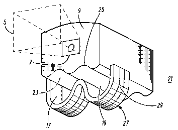
FIG. 1 is a perspective view of a known wearable imager
device.
FIG. 2 is a perspective view of a wearable imager device
embodying the invention.
Description of specific embodiments of the invention

CA 02582343 2007-03-29
WO 2006/039305 PCT/US2005/034710
4
FIG. 1 is a perspective view of a known wearable imager
device 1 for capturing an optical (visible or infra-red)
image of an object of interest, e.g. a package or product
bearing a bar code to be read). The device has a body 3
incorporating (not shown) an optical scanner and reader
device, electronic processing circuitry and a RF
transmitter for sending information relating to the
captured image to a another terminal (e.g. in a unit
carried by the user or held elsewhere). Radiation emitted
by the optical scanner is indicated as a beam 5 which is
issued through a window/lens unit 7 in a front face 9 of
the body 3. A top face 11 incorporates a LED indicator 13
to light to indicate correct operation of the scanning
and reading of an image. The body 3 and its contents are
carried by a user by support on a strap 15. The strap 15
is bent to form two slots 17 and 19 through which two
fingers (not shown) of a user are passed and so that the
body is held supported on the user's fingers.
FIG. 2 is a perspective view of a wearable imager device
21 embodying the invention. Parts of the device 21 shown
with the same reference numerals as those in FIG. 1 have
the same function. In FIG. 2, two curved recesses 23, 25
formed in the underside of the body 3 to facilitate
accommodation of the user's fingers between the body 3
and the strap 15 are shown more clearly (they are also
present in the device of FIG. 1). In the device 21 there
is no LED indicator in the body 3 of the device. Instead
the strap 15 is replaced by a similarly shaped strap 27.
The strap 27 incorporates a flexible band 29 which serves
as a light indicator. The band 29 may be a flexible strip

CA 02582343 2007-03-29
WO 2006/039305 PCT/US2005/034710
formed of.LEDs. The band 29 has connections (not shown)
to a battery (not shown) inside the body 3.
Other light sources incorporated in a flexible
material can be used instead of LEDs, e.g. based on known
5 light emitting technologies such as EL (Electro-
Luminescent, OLED (Organic LED), and lasing fibres.
Further, several different colour sources can be
used, either alongside each other, or twisted together,
to give a number of different colour indications, e,g to
indicate different operational indications relating to
the device 21.
Further, the above light sources can be fabricated
together in one piece in the strap material or woven
together with the strap material, e.g. where of a fibrous
material, such that they form both the strap and the
light indicator in an integral, flexible structure.
The embodiment shown in FIG. 2 is for a finger
mounted device, but the same principle can equally be
applied to wrist, palm and forearm straps by which an
imager device is to be carried.
The device shown in FIG. 2 and the alternative
embodiments of the invention can show one or more of the
following benefits:
(i) There are reduced leverage forces on the finger
or hand of the user, so there is a reduced risk of RSI
and a more comfortable working shift.
(ii) Since the whole length of the strap (or a major
portion of its length) can be used to provide the light
indicator, there is little chance of the user missing the
indication.

CA 02582343 2007-03-29
WO 2006/039305 PCT/US2005/034710
6
(iii) Better sealing of the device body 3 can be
provided as no hole or window is required for the LED
indicator as in FIG. 1. This also provides a more robust
housing.
(iv) A strip of light may be considered to be more
user friendly and easier on the eyes of the user compared
to a spot light source.
(v) A lower level of illumination energy can be
used because it is over a large area, so saving energy
and potential allowing battery weight and size to be
reduced.

Representative Drawing
A single figure which represents the drawing illustrating the invention.
Administrative Status

2024-08-01:As part of the Next Generation Patents (NGP) transition, the Canadian Patents Database (CPD) now contains a more detailed Event History, which replicates the Event Log of our new back-office solution.

Please note that "Inactive:" events refers to events no longer in use in our new back-office solution.

For a clearer understanding of the status of the application/patent presented on this page, the site Disclaimer , as well as the definitions for Patent , Event History , Maintenance Fee  and Payment History  should be consulted.

Event History

Description Date
Application Not Reinstated by Deadline 2010-09-27
Time Limit for Reversal Expired 2010-09-27
Deemed Abandoned - Failure to Respond to Maintenance Fee Notice 2009-09-28
Inactive: Cover page published 2007-06-01
Inactive: Acknowledgment of national entry - RFE 2007-05-28
Letter Sent 2007-05-28
Inactive: First IPC assigned 2007-04-24
Application Received - PCT 2007-04-23
All Requirements for Examination Determined Compliant 2007-03-29
National Entry Requirements Determined Compliant 2007-03-29
Request for Examination Requirements Determined Compliant 2007-03-29
Application Published (Open to Public Inspection) 2006-04-13

Abandonment History

Abandonment Date Reason Reinstatement Date
2009-09-28

Maintenance Fee

The last payment was received on 2008-06-27

Note : If the full payment has not been received on or before the date indicated, a further fee may be required which may be one of the following

  • the reinstatement fee;
  • the late payment fee; or
  • additional fee to reverse deemed expiry.

Please refer to the CIPO Patent Fees web page to see all current fee amounts.

Fee History

Fee Type Anniversary Year Due Date Paid Date
Basic national fee - standard 2007-03-29
Registration of a document 2007-03-29
Request for examination - standard 2007-03-29
MF (application, 2nd anniv.) - standard 02 2007-09-26 2007-07-10
MF (application, 3rd anniv.) - standard 03 2008-09-26 2008-06-27
Owners on Record

Note: Records showing the ownership history in alphabetical order.

Current Owners on Record
MOTOROLA, INC.
Past Owners on Record
AVI ZELIG
JACOB GABAY
SHMUEL BARMAN
YONA NEWMAN
Past Owners that do not appear in the "Owners on Record" listing will appear in other documentation within the application.
Documents

To view selected files, please enter reCAPTCHA code :


To view images, click a link in the Document Description column. To download the documents, select one or more checkboxes in the first column and then click the "Download Selected in PDF format (Zip Archive)" or the "Download Selected as Single PDF" button.

List of published and non-published patent-specific documents on the CPD .

If you have any difficulty accessing content, you can call the Client Service Centre at 1-866-997-1936 or send them an e-mail at CIPO Client Service Centre.


Document
Description 
Date
(yyyy-mm-dd) 
Number of pages   Size of Image (KB) 
Representative drawing 2007-03-29 1 9
Claims 2007-03-29 1 30
Drawings 2007-03-29 1 19
Description 2007-03-29 6 174
Abstract 2007-03-29 2 72
Cover Page 2007-06-01 1 40
Acknowledgement of Request for Examination 2007-05-28 1 177
Reminder of maintenance fee due 2007-05-29 1 112
Notice of National Entry 2007-05-28 1 203
Courtesy - Certificate of registration (related document(s)) 2007-05-28 1 107
Courtesy - Abandonment Letter (Maintenance Fee) 2009-11-23 1 171
PCT 2007-03-29 1 54