Note: Descriptions are shown in the official language in which they were submitted.
CA 02582355 2013-10-01
REINFORCING MATRIX FOR SPOOLABLE PIPE
TECHNICAL FIELD OF INVENTION
[0001] The present invention relates to pipes, and more specifically to a
spoolable
pipe.
BACKGROUND
[0002] Steel pipe is commonly used in the oil and gas industry. This type
of pipe may
be used in the transport of fluids to or from the well such as oil and gas
gathering lines,
flow lines, and fluid and gas injection lines which may be installed on the
surface or
buried. Steel pipe may also be used for downhole applications such as
drilling,
intervention, or production including drill strings, coiled tubing, production
tubing, casing,
and velocity and heater strings, and the like. Carbon steels, however, may be
susceptible
to corrosion by oilfield fluids, such as produced or injected water, brine,
and dissolved
acids from CO2 or H2S, as well as well work-over fluids such as HC1 and HF.
Furthermore, steel pipelines, gathering lines or injection lines are usually
installed using
short (30-40 foot) sections. This requires additional labor and provides the
possibility for
fluid leakage at each fitting. Such labor intensive installation may also lead
to lost
revenues if production or transport of the fluids is suspended during the
installation.
[0003] To resist internal corrosion, steel alloys, non-metallic internal
coatings, or
fiberglass-reinforced epoxy pipe may be used, but all may still have the
disadvantage of
being sectional products. In addition, the wall of a fiberglass-reinforced
epoxy pipe may
be fairly damage intolerant and may require careful handling, installation,
and/or use of
specific back-fill materials. Damage or cracks in the fiberglass-reinforced
epoxy layer can,
in some cases, lead to small leaks or "weeping" of the pipe under pressure. In
some
applications, thermoplastic liners may be used as corrosion protection inside
steel pipe, but
these liners are susceptible to collapse by permeating gases trapped in the
annulus between
the liner and the steel pipe if the pressure of the bore is rapidly decreased.
Unreinforced
thermoplastic pipe, on the other hand, can usually only tolerate relatively
low pressures
especially at elevated temperatures and in the presence of oilfield fluids.
- 1 -
CA 02582355 2007-03-21
[0004] Thermoplastic lined fiberglass pipe designed for relatively moderate
pressure, for
example, 0 to about 500 PSI service may have thin walls that may be damage
intolerant or
may kink or collapse when spooled at moderate spooling strains of about 1-10%.
High
modulus materials such as epoxies may increase the tendency for the thin-
walled pipe to
kink or collapse. Materials such as Kevlar may used for reinforcement but may
be
prohibitively expensive for many applications. Bare fiberglass reinforcement
of, for
example, a thermoplastic liner may be susceptible to corrosion by water,
especially in the
presence of dilute acids, bases, or stress. Abrasion of bare fibers against
each other during
manufacturing, spooling, installation, or operation may cause breakage of
glass fibers and
reduction of hydrostatic strength. Uneven surfaces of the fibers against a
tube liner may
cause point loading; gouging of the fibers into the liner may increase the
tendency to stress
cracking of the liners; individual fibers that can move independently may
spread so as to
allow the liner to extrude past the fiber reinforcement and rupture.
Therefore, there is a need
for a low-cost, corrosion resistant, spoolable, reinforced inner-lined pipe
for such relatively
low pressure applications that is damage tolerant and will not kink when
spooled.
SUMMARY
[0005] Disclosed is a spoolable pipe comprising a matrix that includes
solid matrix with
a tensile modulus of less than about 100,000 psi.
[0006] For example, a spoolable pipe is disclosed that includes an internal
pressure
barrier formed about a longitudinal axis; at least one reinforcing layer
enclosing the internal
pressure barrier and comprising fibers and a solid hydrocarbon matrix, where
the solid
hydrocarbon matrix is solid at about 25 'V, and may also include an external
layer enclosing
the least one reinforcing layer. The hydrocarbon matrix may comprise
hydrocarbons having
a molecular weight of less than about 10,000 grams/mole.
[0007] In some embodiments, the reinforcing layer includes fibers that
comprise glass,
an aramid, a carbon, a ceramic, a metal, a mineral, or a polymer, or
combinations thereof. A
reinforcing layer may comprise at least two plies of fibers, and in some
embodiments, at
least two plies of fibers may have at least a partial helical orientation
relative to the
longitudinal axis. Such fibers may be embedded in matrix.
-2-
CA 02582355 2007-03-21
[0008] The solid hydrocarbon matrix of a disclosed spoolable tube may
comprise up to
about 30%, up to about 50%, or even up to about 70% by volume of a reinforcing
layer
and/or may comprise up to about 15% by weight of a reinforcing layer. For
example, the
matrix may comprise between about 10% and about 70% by volume. In some
embodiments,
the solid hydrocarbon matrix may have a tensile strength of less than about
1000 psi. In
other embodiments, the permeability of a disclosed hydrocarbon matrix
increases with
temperature faster than the permeability of an internal pressure barrier or
liner increases with
temperature.
[0009] In some embodiments, the solid hydrocarbon matrix included in the
spoolable
tube may have a content of at least 10% by weight of hydrocarbons with a
molecular weight
of less than about 4,000 grams/mole and/or may have a solid hydrocarbon matrix
with a
molecular weight of about 200 to about 8,000 grams/mole. Contemplated
hydrocarbons may
include straight-chain alkanes, cycloalkanes, branched alkanes, and/or
aliphatic compounds.
Hydrocarbons contemplated herein may also include alkenes, alkynes, and
aromatic
functionalities.
[0010] Also disclosed herein is a spoolable pipe that includes an internal
pressure barrier
formed about a longitudinal axis, at least one reinforcing layer enclosing the
internal
pressure barrier and comprising fibers and a solid matrix with a tensile
modulus between
about 10 and 90,000 psi, or about 10 to about 10,000 psi, wherein said
reinforcing layer is
formed at least by applying to said fibers a substantially liquid matrix
composition having a
viscosity between about 10 and about 5,000 cPs at 25 C, or between about 10
and about
10,000 cPs at 25 C. In some embodiments, the substantially liquid matrix
composition is
capable of flowing between the fibers of the reinforcing layer.
[0011] The substantially liquid matrix composition may have a viscosity
between about
100 and about 1000 cPs. In some embodiments, the substantially liquid matrix
composition
is an emulsion, a suspension, a colloid, a immiscible fluid blend, or two-
phase system, and
may further include an emulsifier, tackifier, binder, and/or surfactant. In
one embodiment,
the substantially liquid matrix is an emulsion. In another embodiment, the
substantially
liquid matrix comprises a water-based dispersion, e.g. that includes polymer
particles. The
-3-
CA 02582355 2007-03-21
substantially liquid matrix composition may include at least one of:
polyethylene,
polyethylene oligomers, polypropylene, polypropylene oligomers, polyolefins,
polyolefin
oligomers, paraffin waxes, or a grease.
[0012] In some embodiments, the substantially liquid matrix composition
comprises
polymer particles. Such polymer particles may have an average diameter between
about 10
nm and about 10 vim.
[0013] The internal pressure barrier or liner of a disclosed spoolable tube
may comprise
at least one of: a metal, and/or a polymer such as a polyolefin, a
polyethylene, cross-linked
polyethylene, polyvinylidene fluoride, polyamide, polypropylene, polybutylene,
polybutadiene, polyvinylchloride, polyethylene terphthalate, or polyphenylene
sulfide or
combinations thereof The barrier may have distinct separate layers or may
include
combinations of materials such as an alloy, blend, copolymer or block polymer.
The internal
pressure barrier may also include organic or inorganic solids.
[0014] In some embodiments, the permeability of a reinforcing layer or
hydrocarbon
matrix of a disclosed spoolable tube may be higher than the permeability of an
internal
pressure barrier and/or the permeability of an external layer may be higher
than the
permeability of the hydrocarbon matrix or a reinforcing layer. In some
embodiments, the
permeability of an external layer may be less than the permeability of the
reinforcing layer or
hydrocarbon matrix.
[0015] A disclosed spoolable pipe may include an external layer that
comprises, for
example, at least one of: polyethylene, cross-linked polyethylene,
polyvinylidene fluoride,
polyamide, polybutylene, polypropylene, polyethylene terphthalate, or
polyphenylene
sulfide, or a combination thereof, either as distinctly separate layers or as
alloys, blends,
copolymers, or block copolymers. An exemplary external layer includes a foam
that
comprises for example, at least one of: a thermoset polymer, a thermoplastic
polymer,
elastomer, rubber, a closed cell foam, and an open cell foam. The external
layer may include
organic or inorganic solids. In some embodiments, such an external layer is
perforated.
Disclosed spoolable pipes may further comprise an energy conductor. In other
-4-
CA 02582355 2007-03-21
embodiments, a spoolable pipe disclosed herein may include a fire retardant UV
stabilizer,
oxidative stabilizer, thermal stabilizer, and/or a pigment.
[0016] The disclosed reinforcing material may include fibers which are at
least partially
coated by said solid hydrocarbon matrix and/or fibers that may be embedded in
said solid
hydrocarbon matrix.
[0017] Also provided herein is a method for producing a spoolable tube
comprising:
providing an inner layer of said spoolable tube; applying a substantially
liquid matrix
composition comprising at least one of: polyethylene, polyethylene oligomers,
polypropylene, polypropylene oligomers, polyolefins, polyolefin oligomers, a
wax, and/or a
grease to fibers at a temperature between about 20 C and about 40 C; drying
or curing said
fibers so that a solid matrix composition between the fibers is formed; and
winding said tow
around said inner layer. The substantially liquid matrix composition may be
applied at about
25 C. The applying step may occur substantially during the winding step. In
some
embodiments, the drying step may occur after, during, or before the winding
step.
[0018] In another embodiment, a method for producing a spoolable tube is
provided that
comprises: providing an inner layer of the spoolable tube; applying a
hydrocarbon matrix
comprising hydrocarbons having an average molecular weight of less than about
20,000
grams/mole to fibers by dissolving the hydrocarbons in a solvent; cooling or
evaporating the
solvent from said fibers so that a solid hydrocarbon matrix is formed on or
around the fibers;
and winding said fibers around said inner layer. The hydrocarbon matrix may be
applied at
about 25 C.
[0019] Alternatively, a method for producing a spoolable tube is provide
that comprises:
providing an inner layer of the spoolable tube; melting a hydrocarbon matrix
comprising
hydrocarbons having an average molecular weight of less than about 20,000
grams/mole;
applying the melted hydrocarbon matrix to fibers; cooling the hydrocarbon
matrix so that a
solid hydrocarbon matrix is formed on or around the fibers; and winding said
fibers around
said inner layer. In some embodiments, a substantially solid hydrocarbon
matrix
composition is a wax. The methods may further comprise forming a tow
comprising said
-5-
CA 02582355 2013-10-01
fibers. The hydrocarbon matrix composition may be applied at a temperature
above its
melting point, for example at about 40 to about 150 C.
[0020] In some embodiments, the solid hydrocarbon matrix is formed by cross-
linking
or gelling the hydrocarbons. Such gelling or cross-linking of the hydrocarbon
matrix may
improve the thermal resistance, chemical resistance, or mechanical properties
of the
matrix.
[0021] The methods include those wherein an applying step occurs
substantially in-
line with the production of the fibers. The applying step of the disclosed
methods may
occur, e.g. substantially during the winding step. The cooling or solvent
evaporation step
may occur after said winding step. In some embodiments, disclosed methods may
also
include forming a tow comprising said fibers.
[0021a] The present invention also provides a spoolable pipe, comprising:
an internal
pressure barrier formed about a longitudinal axis; at least one reinforcing
layer enclosing
the internal pressure barrier and comprising fibers and a solid hydrocarbon
matrix, wherein
said solid hydrocarbon matrix has a tensile modulus of about 100 to about
10,000 psi,
wherein said solid hydrocarbon matrix is solid at about 25 C and said matrix
comprises
hydrocarbons having an average molecular weight of less than about 20,000
grams/mole;
and an external layer enclosing the at least one reinforcing layer.
BRIEF DESCRIPTION OF THE DRAWINGS
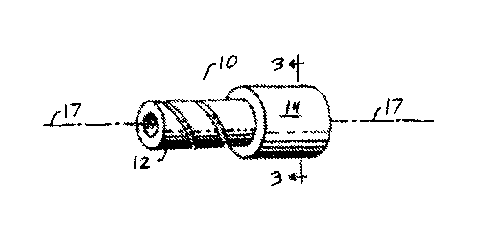
[0022] FIGURE 1 is a side view, partially broken away, of a spoolable tube
that
includes an inner pressure barrier and a reinforcing layer.
[0023] FIGURE 2 is a cross-sectional view of a spoolable tube having an
inner
pressure barrier surrounded by multiple reinforcing layers.
[0024] FIGURE 3 is cross-sectional view of a spoolable tube having an inner
pressure
barrier surrounded by a reinforcing layer that includes two plies of fibers
with an abrasion
layer between the two plies.
[0025] FIGURE 4 is a side view, partially broken away, of a spoolable tube
having an
inner pressure barrier, a reinforcing layer, and an external layer.
[0026] FIGURE 5 is a side view, partially broken away, of a spoolable tube
that
includes an energy conductor.
- 6 -
CA 02582355 2013-10-01
[0027] FIGURE 6 indicates various properties of tows that include various
low
molecular weight hydrocarbons with glass fibers.
[0028] FIGURE 7 shows the distribution of hydrocarbons in an exemplary
solid
hydrocarbon matrix.
DETAILED DESCRIPTION
- 6a -
CA 02582355 2007-03-21
[0029] To provide an overall understanding, certain illustrative
embodiments will now
be described; however, it will be understood by one of ordinary skill in the
art that the
systems and methods described herein can be adapted and modified to provide
systems and
methods for other suitable applications and that other additions and
modifications can be
made without departing from the scope of the systems and methods described
herein.
[0030] Unless otherwise specified, the illustrated embodiments can be
understood as
providing exemplary features of varying detail of certain embodiments, and
therefore, unless
otherwise specified, features, components, modules, and/or aspects of the
illustrations can be
otherwise combined, separated, interchanged, and/or rearranged without
departing from the
disclosed systems or methods. Additionally, the shapes and sizes of components
are also
exemplary and unless otherwise specified, can be altered without affecting the
scope of the
disclosed and exemplary systems or methods of the present disclosure.
[0031] Disclosed herein is a spoolable tube and methods for making the
same, that
provides a path for conducting fluids (i.e., liquids and gases) along the
length of the
spoolable tube. For example, the spoolable tube can transmit fluids down a
well hole for
operations upon the interior surfaces of the well hole, the spoolable tube can
transmit fluids
or gases to hydraulic or pneumatic machines operably coupled to the spoolable
tube, and/or
the spoolable tube can be used to transmit fluids, underwater, underground, or
on surface
systems from well holes or other equipment to transmission, distribution
pipelines or other
equipment. Accordingly, the spoolable tube disclosed herein can provide a
conduit for
powering and controlling hydraulic and/or pneumatic machines, and/or act as a
conduit for
fluids, for example gases or liquids. In some embodiments, the spoolable tubes
disclosed
herein are used for relatively low pressure applications, where the pressure
of a fluid being
transported by a disclosed tube is about 1 to about 1000 psi, or about 10 to
about 500 psi.
Such spoolable tubes comprise a reinforcing layer that includes a matrix with
a tensile
modulus of less than 100,000 psi, e.g. a tensile modulus between about 1 and
about 90,000
psi, between about 10 and 90,000 psi, between about 100 and about 10,000 psi.
[0032] For convenience, before further description, certain terms employed
in the
specification, examples, and appended claims are collected here. These
definitions should
-7-
CA 02582355 2007-03-21
be read in light of the reminder of the disclosure and understood as by a
person of skill in the
art.
[0033] The articles "a" and "an" are used herein to refer to one or to more
than one (i.e.
to at least one) of the grammatical object of the article. By way of example,
"an element"
means one element or more than one element.
[0034] The term "aliphatic" is an art-recognized term and includes linear,
branched, and
cyclic alkanes, alkenes, or alkynes. In certain embodiments, aliphatic groups
in the present
disclosure are linear or branched and have from 10 to about 100 carbon atoms,
12 to about
50 carbons, or even 12 to about 35 carbons.
[0035] The term "alkyl" is art-recognized, and includes saturated aliphatic
groups,
including straight-chain alkyl groups, branched-chain alkyl groups, cycloalkyl
(alicyclic)
groups, alkyl substituted cycloalkyl groups, and cycloalkyl substituted alkyl
groups. In
certain embodiments, a straight chain or branched chain alkyl has about 30 or
fewer carbon
atoms in its backbone (e.g., C1-C30 for straight chain, C3-C30 for branched
chain), and
alternatively, about 20 or fewer. Likewise, cycloalkyls have from about 3 to
about 10 carbon
atoms in their ring structure, and alternatively about 5, 6 or 8 carbons in
the ring structure.
[0036] Moreover, the term "alkyl" (or "lower alkyl") includes both
"unsubstituted
alkyls" and "substituted alkyls", the latter of which refers to alkyl moieties
having
substituents replacing a hydrogen on one or more carbons of the hydrocarbon
backbone.
Such substituents may include, for example, a halogen, a hydroxyl, a carbonyl
(such as a
carboxyl, an alkoxycarbonyl, a formyl, or an acyl), a thiocarbonyl (such as a
thioester, a
thioacetate, or a thioformate), an alkoxyl, a phosphoryl, a phosphonate, a
phosphinate, an
amino, an amido, an amidine, an imine, a silyl, a cyano, a nitro, an azido, a
sulfhydryl, an
alkylthio, a sulfate, a sulfonate, a sulfamoyl, a sulfonamido, a sulfonyl, a
heterocyclyl, an
aralkyl, metals, metal ions, or an aromatic or heteroaromatic moiety. It will
be understood by
those skilled in the art that the moieties substituted on the hydrocarbon
chain may
themselves be substituted, if appropriate. For instance, the substituents of a
substituted alkyl
may include substituted and unsubstituted forms of amino, azido, imino, amido,
phosphoryl
(including phosphonate and phosphinate), sulfonyl (including sulfate,
sulfonamido,
-8-
CA 02582355 2007-03-21
sulfamoyl and sulfonate), and silyl groups, as well as ethers, alkylthios,
carbonyls (including
ketones, aldehydes, carboxylates, and esters), -CF3, -CN and the like.
Exemplary substituted
alkyls are described below. Cycloalkyls may be further substituted with
alkyls, alkenyls,
alkoxys, alkylthios, aminoalkyls, carbonyl-substituted alkyls, -CF3, -CN, and
the like.
[0037] The term "aralkyl" is art-recognized, and includes alkyl groups
substituted with
an aryl group (e.g., an aromatic or heteroaromatic group).
[0038] The terms "alkenyl" and "alkynyl" are art-recognized, and include
unsaturated
aliphatic groups analogous in length and possible substitution to the alkyls
described above,
but that contain at least one double or triple bond respectively.
[0039] Unless the number of carbons is otherwise specified, "lower alkyl"
refers to an
alkyl group, as defined above, but having from one to ten carbons,
alternatively from one to
about six carbon atoms in its backbone structure. Likewise, "lower alkenyl"
and "lower
alkynyl" have similar chain lengths.
[0040] The term "hydrocarbon" is art-recognized and refers to all
permissible
compounds having at least one hydrogen and one carbon atom. For example,
permissible
hydrocarbons include acyclic and cyclic, branched and unbranched, carbocyclic
and
heterocyclic, aromatic and nonaromatic organic compounds that may be
substituted or
unsubstituted, for example, alkyl moieties. In some embodiments, hydrocarbons
disclosed
herein have a molecular weight less than about 50,000, less than about 30,000,
less than
about 10,000, less than about 5,000, less than about 3,000, or even less than
about 2,000
g/mol.
[0041] The term 'olefin' refers to unsaturated, aliphatic hydrocarbons. The
unsaturated,
aliphatic hydrocarbons may be substituted or unsubstituted.
[0042] The term "solid" refers to a substance that is resistant to flow,
e.g. substantially
solid at room temperature (25 C.).
[0043] The term "grease" refers to a composition that is organic or
inorganic,
substantially water-insoluble, and semi-solid at room temperature.
[0044] The term "wax" will be understood to encompass any composition that
is
substantially solid at room temperature, and can be used at a low viscosity or
high
-9-
CA 02582355 2007-03-21
temperature, and then cooled to room temperature during the formation of a
product
disclosed herein. A wax melts without significant decomposition at a
temperature above
about 40 C, for example, with a melting point of about 40 C to about 120 C
or about 40
C to about 90 C. Wax may include an organic compound that is substantially
carbon and
hydrogen based, but may include elements such as oxygen, nitrogen silicon
and/or cationic
and anionic moieties. Exemplary waxes include fossil waxes such as petroleum
waxes, e.g.
ozokerite, macrocristalline paraffin waxes, microcrystalline paraffin waxes,
montan waxes,
plant waxes such as carnauba wax, candelilla wax and the like, waxes that
include silicon or
silicone, waxes of animal origin such as beeswax, lanolin and the like, and
also
semisynthetic waxes such as amide waxes, e.g., distearylethylenediamine, and
also fully
synthetic waxes such as polyolefin waxes, e.g., polyethylene and polypropylene
waxes,
Fischer-Tropsch waxes, fluorinated waxes such as polytetrafluoroethylene and
polyethylene-
polytetrafluoroethylene copolymers, and also polyoxidates of Fischer-Tropsch
waxes and of
polyolefin waxes. Waxes include compounds that are esters of long-chain
aliphatic alcohols
(for example C16 and above) with long-chain fatty acids. Such esters and acids
are
preferably straight-chain compounds, and may be saturated or unsaturated.
Examples of
acids which may be used include stearic acid, palmitic acid and oleic acid and
mixtures of
two or more thereof. Waxes derived from long-chain aliphatic compounds may
include
hydrocarbons. In addition to esters of the long-chain acids as described above
there may be
mentioned salts such as, for example, aluminium stearate.
[0045] The
term "substituted" is art-recognized and refers to all permissible
substituents
of organic or inorganic compounds. In a broad aspect, the permissible
substituents include
acyclic and cyclic, branched and unbranched, carbocyclic and heterocyclic,
aromatic and
nonaromatic substituents of organic or inorganic compounds. Illustrative
substituents
include, for example, those described herein above. The permissible
substituents may be one
or more and the same or different for appropriate organic compounds. For
purposes of this
disclosure, the heteroatoms such as silicon may have hydrogen substituents,
halogen
substituents, and/or any permissible substituents of organic or inorganic
compounds
described herein which satisfy the valences of the heteroatoms. This
disclosure is not
-10-
CA 02582355 2007-03-21
intended to be limited in any manner by the permissible substituents of
organic or inorganic
compounds.
[0046] It will be understood that "substitution" or "substituted with"
includes the
implicit proviso that such substitution is in accordance with permitted
valence of the
substituted atom and the substituent, and that the substitution results in a
stable compound,
e.g., which does not spontaneously undergo transformation such as by
rearrangement,
cyclization, elimination, or other reaction.
[0047] The definition of each expression, e.g. alkyl, m, n, R, X, etc.,
when it occurs
more than once in any structure, is intended to be independent of its
definition elsewhere in
the same structure unless otherwise indicated expressly or by the context.
[0048] In one aspect, this disclosure provides for a material, such as a
reinforcing layer
in a spoolable pipe, that includes fibers and a hydrocarbon matrix. The
hydrocarbon matrix
may be solid at room temperature, but have a lower viscosity at a higher
temperature so that
such matrix can be applied in liquid form to, for example, fibers.
Alternatively, the matrix
may be formed, at least in part, by applying a substantially liquid matrix
composition having
a viscosity of between about 10 and about 10,000 cPs at 25 C.
[0049] The hydrocarbon matrix may include hydrocarbons such as aliphatic
compounds,
e.g straight-chain alkanes, cycloalkanes, or branched alkanes. In other
embodiments, the
hydrocarbon matrix may include a wax, such as defined above, or a grease, for
example a
silicone grease, elastomers, rubbers such as butadiene acrylonitrile (NBR) or
hydrogenated
nitrile butadiene rubber, tars, asphalts, polymer solutions or blends,
emulsions, gels or
combinations of these or other hydrocarbons disclosed herein.
[0050[ Exemplary hydrocarbons include those compounds that comprise the
structure
[0051]
[0052] where x may independently for each occurrence be an integer from 0
to 2; R may
independently for each occurrence be hydrogen, alkyl, alkenyl, alkynyl, aryl,
alkoxy,
hydroxyl, halogen, amino, nitro, sulfhydryl, amido, phosphonate, phosphinate,
silyl,
-11-
CA 02582355 2007-03-21
carboxyl, ether, alkylthio, ester, a metal or metal ion, or the like, and n is
an integer from
about 5 to about 300, about 7 to about 100, about 12 to about 25, or about 15
to about 30.
[0053] Such hydrocarbons that may be included in a matrix may have a
molecular
weight or weight average molecular weight of less than about 50,000, less than
about
30,000, less than about 20,000, or even less than about 10,000 g/mol. For
example, a solid
hydrocarbon contemplated herein may have a molecular weight of about 200 to
about 8,000
g/mol, about 400 to about 12,000 g/mol, or about 250 to about 15,000 g/mol. In
some
embodiments, a solid hydrocarbon matrix may have between about 10 and about
2000
repeating monomeric units, e.g. about 10 to about 1500, or about 100 to about
1500
repeating units. A hydrocarbon matrix may have a content of at least about 5%,
at least
about 10%, or even at least about 20% by weight of hydrocarbons with a
molecular weight
of less than for example 20,000, less than about 10,000 or even less that
about 5,000, or less
that about 4,000 grams/mol. A solid hydrocarbon matrix or wax may have a
weight average
molecular weight falling within the ranges set forth above. For example, a
solid
hydrocarbon matrix may include such waxes as Microsere 5701.
[0054] For example, an elemental analysis of a such a substantially
hydrocarbon matrix
may include C,I-IyA,RmR'mR",,,Mr, where R, R' and R" may each independently
include a
halogen such as F, Cl or I; A is a heteroatom; M is a metal and where x is
about 1.0; y may
be about 1.0-3.0 inclusive ; z is about 0-3.0; m is about 0-3.0 and n is about
0-1Ø In some
embodiments, x is about 1.0; y is about 1.5 to 2; z is m is <1 and n is <1.
There may
also be elemental compositions that include more than one type of heteroatom,
halogen or
metal.
[0055] In an exemplary embodiment, a hydrocarbon matrix may have a melting
point
above about 40 C, for example, a hydrocarbon matrix may have a melting point
between
about 35 C and 120 C, or between about 40 C and about 100 C, or between
about 40 C
and about 80 C.
[0056] Alternatively, the matrix may include a polymer such as a
thermoplastic, e.g.
polyethylene or polyethylene oligomers, polypropylene, polypropylene
oligomers,
polyolefins, and/or polyolefin oligomers. A contemplated reinforcing layer
comprises a
-12-
CA 02582355 2007-03-21
matrix that may include a thermoplastic polymer, with a molecular weight, or
average
molecular weight, above e.g. 10,000 g/mol, or above about 20,000 g/mol. Such
solid matrix
may formed for example by providing a substantially liquid matrix composition
that includes
such a polymer, a wax, and/or a grease, wherein the liquid matrix forms a
solid after a period
of time, e.g. by drying, curing and/or crosslinking. The substantially liquid
matrix, in certain
embodiments, has a viscosity less than about 1000 cPs, e.g. a viscosity
between about 100
and about 1000, between about 150 and about 800 cPs at 25 C. A low viscosity
may allow
the substantially liquid matrix composition to flow between small diameter
fibers of the
reinforcing layer, and/or may facilitate filament winding.
[0057] Such a substantially liquid matrix may be in the form of an
emulsion, a
suspension, a colloid, an immiscible fluid blend, an ionic liquid, and/or a
two phase system.
A substantially liquid matrix can comprise a solution of hydrocarbons in an
appropriate
solvent. In some embodiments, a substantially liquid matrix may be an
emulsion, e.g. an oil-
in-water emulsion or an water-in oil emulsion. An emulsion may have both the
dispersed
and continuous phase substantially liquid. In an embodiment, the emulsion
comprises
polymer particles, e.g. particles with an average diameter of about 10 nm to
about 1001.tm,
or about 100 nm to about 1 jim. A contemplated emulsion may include an
emulsifier,
tackifier, binder, and/or a surfactant.
[0058] For example, a substantially liquid composition for use in forming a
solid matrix
may be a latex matrix or dispersion, e.g. a water-based dispersion of sub-
micron polymer
particles. When the water evaporates, the polymer particles may coalesce to
form a solid,
e.g. a solid film. Alternatively, a substantially liquid composition may
include an anionic or
cationic additive or composition which upon evaporation, drying, curing, or
gelling are
capable of form a solid matrix. For example, such composition may comprise
amine or
ammonium moieties. In some embodiments, a substantially liquid composition may
include
inorganic solids.
[0059] A reinforcing material or layer may include fibers. Such a layer may
include
fibers in one or more plies, or the fibers may be randomly oriented, or the
material may
include fibers in both configurations.
-13-
CA 02582355 2007-03-21
[0060] In one embodiment, the reinforcing layer can include two plies,
which can
optionally be counter-wound unidirectional plies. Such plies can be wound or
formed
around a inner object, for example, an inner pipe layer. The reinforcing
layer(s) can include
two plies, which can optionally be wound in about equal but opposite helical
directions. In
other embodiments, the reinforcing material can include three, four, five,
six, seven or eight,
or more plies of fibers, each ply independently wound, for example, in a
helical orientation
relative to the longitudinal axis. Plies may have a different helical
orientation with respect to
another ply, or may have the same helical orientation. The reinforcing layer
may include
plies and/or fibers that have a partially and/or a substantially axial
orientation. The
reinforcing layer may include plies of fibers with another material disposed
between each
ply, such as for example, an abrasion resistant material disposed between each
ply, or
optionally disposed between only certain plies. In some embodiments, an
abrasion resistant
layer is disposed between plies that have a different helical orientation.
[0061] When the reinforcing material or layer is part of a device or object
with a
longitudinal axis, e.g. a spoolable pipe, such reinforcing layers can include
fibers having at
least a partially helical orientation relative to this axis. The fibers may
have a helical
orientation between substantially about thirty degrees and substantially about
seventy
degrees relative to the longitudinal axis. For example, the fibers may be
counterwound with
a helical orientation of about 400, 450, +500, +55 , and/or +60 . The
reinforcing layer may
include fibers having multiple, different orientations about the longitudinal
axis.
[0062] Exemplary fibers include but are not limited to graphite, glass,
carbon, KEVLAR,
aramid, fiberglass, boron, polyester fibers, polyamide, ceramic, inorganic or
organic polymer
fibers, mineral based fibers such as basalt fibers, metal fibers, and wire.
For example, fibers
can include glass fibers that comprise e-glass, e-cr glass, Advantex , s-
glass, d-glass,
borosilicate glass, soda-lime glass or a corrosion resistant glass.
[0063] The fibers can include structural fibers and flexible yarn
components. The
structural fibers can be formed of carbon, aramid, thermoplastic, polyester,
polyamide,
carbon, KEVLAR, inorganic compounds such as basalt or boron, metal and/or
glass. The
flexible yarn components, or braiding fibers, can be formed of either
polyamide, polyester,
-14-
CA 02582355 2007-03-21
aramid, thermoplastic, carbon, KEVLAR, boron, inorganic compounds such as
basalt or
boron, glass and/or ceramic. The fibers included in a reinforcing material can
be woven,
braided, knitted, stitched, circumferentially, axially or hoop wound,
helically wound, and/or
other textile foini to provide an orientation as provided herein (e.g., in an
embodiment, with
an orientation between substantially about thirty degrees and substantially
about seventy
degrees relative to a longitudinal axis of an object). The fibers can be
biaxially or triaxially
braided.
[0064] The reinforcing layer or material contemplated herein may include
fibers that are
at least partially coated by a disclosed matrix, and may include fibers that
are embedded
within a matrix, or may include fibers with a matrix between at least some of
the fibers, or
may include a combination. The reinforcing material may comprise up to about
30% of
matrix by volume, up to about 50% of matrix by volume, up to about 70% of
matrix by
volume, or even up to about 80% or higher by volume.
[0065] The reinforcing material contemplated herein may comprise more than
about 5%,
more than about 10%, more than about 20% or even more than about 30% by weight
of solid
hydrocarbon matrix.
[0066] As contemplated herein, the disclosed reinforcing material may also
include
polymers such as thermoplastics, for example polyolefins. For example, a
reinforcing
material may also include polyethylene such as low density polyethylene,
medium density
polyethylene, linear low density polyethylene, high density polyethylene,
ultra-high
molecular weight polyethylene, polypropylene, cross-linked polyethylene,
polybutylene,
polybutadiene, or polyvinylchloride. The reinforcing material may further
include pigments,
plasticizers, flame retardants, UV stabilizers, thermal stabilizers, oxidative
stabilizers, water
resistant materials, water absorbing materials, hydrocarbon resistant
materials, hydrocarbon
absorbent materials, penneation resistant materials, permeation facilitating
materials,
lubricants, fillers, compatibilizing agents, coupling agents such as silane
coupling agents,
surface modifiers, conductive materials, thermal insulators or other
additives, or a
combination of these.
-15-
CA 02582355 2007-03-21
[0067] Also contemplated herein are one or more methods for fabricating or
making a
reinforcing material or layer. Such a reinforcing material or layer may be
fabricated by
applying a composition comprising hydrocarbon that is substantially in liquid
form, for
example, a disclosed hydrocarbon at a temperature greater than about 40 C, or
a
substantially liquid composition such as an emulsion which may be e.g. at
about room
temperature to fibers, for example, to a ribbon or bundle of fibers, to form a
material. If a
hydrocarbon is applied at a temperature greater than 40 C, the reinforcing
layer or material
can then be cooled to room temperature, forming a matrix. If a substantially
liquid
composition is applied at, e.g. room temperature, the composition can be e.g.
dried to form a
solid matrix. The hydrocarbon and/or substantially liquid composition may be
applied in
line with fiber manufacture or in a secondary process, or it may be applied
during the fiber
winding operation of the tubing manufacture. Disclosed matrix components such
as
hydrocarbons can also be applying in liquid form by for example, forming an
emulsion of
hydrocarbons in water and then applying the composition to fibers. Such
application may be
followed by evaporation, drying, gelling, curing, or polymerization of the
liquid. The matrix
may be applied in-line with fiber manufacture, e.g. as part of the fiber
sizing or as a coating,
and/or applied in a secondary fiber coating operation to form a coated tow,
strand, ribbon,
rope, yarn or the like. It may also be applied in-line with a filament winding
operation.
[0068] Figure 1 illustrates a spoolable tube 10 constructed of an internal
pressure barrier
12 and a reinforcing layer 14. The spoolable tube can be generally formed
along a
longitudinal axis 17. Although illustrated in Figure 1 as having a circular
cross-section, the
disclosed spoolable tube can have a variety of tubular cross-sectional shapes,
including but
not limited to circular, oval, rectangular, square, polygonal, and/or others.
[0069] The internal pressure barrier 12, otherwise referred to as a liner
or a fluid barrier,
can serve as a pressure containment member to resist leakage of internal
fluids from within
the spoolable tube 10. In some embodiments, the internal pressure barrier 12
can include a
polymer, a thermoset plastic, a thermoplastic, an elastomer, a rubber, a co-
polymer, and/or a
composite. The composite can include a filled polymer and a nano-composite, a
polymer/metallic composite, and/or a metal (e.g., steel, copper, and/or
stainless steel).
-16-
CA 02582355 2007-03-21
Accordingly, an internal pressure barrier 12 can include one or more of a
polyethylene, a
cross-linked polyethylene, a polybutylene, a polyvinylidene fluoride, a
polyamide,
polyethylene terphthalate, polyphenylene sulfide and/or a polypropylene, or
combinations of
these materials, either as distinct layers or as blends, alloys, copolymers,
block copolymers
or the like. The internal pressure barrier may also contain solid state
additives. In one
embodiment, the internal pressure barrier 12 includes a modulus of elasticity
greater than
about approximately 50,000 psi, and/or a strength greater than about
approximately 1,000
psi. In some embodiments, the internal pressure barrier 12 can carry at least
fifteen percent
of the axial load along the longitudinal axis, at least twenty-five percent of
the axial load
along the longitudinal axis, or at least thirty percent of the axial load
along the longitudinal
axis at a termination, while in some embodiments, the internal pressure
barrier 12 can carry
at least fifty percent of the axial load along the longitudinal axis at a
termination. Axial load
may be determined at the ends of a tube. For example, at the ends, or a
termination, of a
tube, there may be a tensile (e.g. axial) load equal to the internal pressure
multiplied by the
cross-sectional area of the inner diameter of the pipe.
[0070] Referring back to Figure 1, the spoolable tube 10 can also include
one or more
reinforcing layers 14. In one embodiment, the reinforcing layers can include
fibers having at
least a partially helical orientation relative to the longitudinal axis of the
spoolable tube. The
fibers may have a helical orientation between substantially about thirty
degrees and
substantially about seventy degrees relative to the longitudinal axis 17. For
example, the
fibers may be counterwound with a helical orientation of about 40 , 45 , +50
, +55 ,
and/or +60 . The reinforcing layer may include fibers having multiple,
different orientations
about the longitudinal axis. Accordingly, the fibers may increase the load
carrying strength
of the reinforcing layer(s) 14 and thus the overall load carrying strength of
the spoolable tube
10. In another embodiment, the reinforcing layer may carry substantially no
axial load
carrying strength along the longitudinal axis at a termination.
[0071] The reinforcing layer(s) 14 can be formed of a number of plies of
fibers, each ply
including fibers. In one embodiment, the reinforcing layer(s) 14 can include
two plies,
which can optionally be counterwound unidirectional plies. The reinforcing
layer(s) can
-17-
CA 02582355 2007-03-21
include two plies, which can optionally be wound in about equal but opposite
helical
directions. The reinforcing layer(s) 14 can include three, four, five, six,
seven, eight, or
more plies of fibers, each ply independently wound in a helical orientation
relative to the
longitudinal axis. Plies may have a different helical orientation with respect
to another ply,
or may have the same helical orientation. The reinforcing layer(s) 14 may
include plies
and/or fibers that have a partially and/or a substantially axial orientation.
The reinforcing
layer may include plies of fibers with a tape or coating, such as a tape or
coating that
includes a abrasion resistant material or polymer, disposed between each ply,
underneath the
plies, on the outside of the plies, or optionally disposed between only
certain plies. In some
embodiments, an abrasion resistant layer is disposed between plies that have a
different
helical orientation.
[0072] The fibers can include structural fibers and flexible yarn
components. The
structural fibers can be formed of graphite, glass, carbon, KEVLAR, aramid,
fiberglass,
boron, polyester fibers, polyamide, ceramic, inorganic or organic polymer
fibers, mineral
based fibers such as basalt fibers, metal fibers, and wire. The flexible yarn
components, or
braiding fibers, graphite, glass, carbon, KEVLAR, aramid, fiberglass, boron,
polyester fibers,
polyamide, ceramic, inorganic or organic polymer fibers, mineral based fibers
such as basalt
fibers, metal fibers, and wire. The fibers included in the reinforcing
layer(s) 14 can be
woven, braided, knitted, stitched, circumferentially wound, helically wound,
axially oriented,
and/or other textile form to provide an orientation as provided herein (e.g.,
in the exemplary
embodiment, with an orientation between substantially about thirty degrees and
substantially
about seventy degrees relative to the longitudinal axis 17). The fibers can be
biaxially or
triaxially braided.
[0073] In one embodiment, the reinforcing layer(s) 14 includes fibers
having a modulus
of elasticity of greater than about 5,000,000 psi, and/or a strength greater
than about 100,000
psi. In some embodiments, an adhesive can be used to bond the reinforcing
layer(s) 14 to
internal pressure barrier 12. In other embodiments, one or more reinforcing
layers are
substantially not bonded to one or more of other layers, such as the inner
liner, internal
pressure barriers, or external layer(s).
-18-
CA 02582355 2007-03-21
[0074] Figure 2 illustrates a cross-section of a circular spoolable tube 10
having an inner
pressure barrier liner 12 and a first reinforcing layer 14A, a second
reinforcing layer 14B,
and a third reinforcing layer 14C. Each of the reinforcing layers 14A-C may be
formed of
fibers, and each of the reinforcing layers 14A-C successively encompasses and
surrounds the
underlying reinforcing layer and/or pressure barrier 12.
[0075] The fibers in each of the reinforcing layers 14A-C can be selected
from the same
or different material. For example, the first reinforcing layer 14A can
comprise helically
oriented glass fibers; second reinforcing layer 14B can comprise a ply having
helically
oriented glass fiber at the same angle, but at an opposite orientation of the
first reinforcing
layer 14A; and third reinforcing layer 14C can comprise plies of fibers having
a clockwise
and counter-clockwise helically oriented glass fibers. Further, the different
reinforcing
layers 14A-C can include different angles of helical orientation. For example,
in one
embodiment, the different layers can have angles of orientation between
substantially about
thirty degrees and substantially about seventy degrees, relative to the axis
17. Alternatively,
the different layers can have angles of orientation between substantially
about forty-six
degrees and substantially about fifty-two degrees, relative to the axis 17. In
some
embodiments, the different layers 14A-C can have more than one fiber within a
layer, such
as carbon and glass, and/or carbon and aramid, and/or glass and aramid.
Further, the
different layers 14A-C may each comprise multiple plies, each independent ply
having a
different, or substantially the same, helical orientation with respect to
other plies within a
layer.
[0076] The reinforcing layer(s) 14 can include, in one or more embodiments
of this
disclosure, a hydrocarbon such as disclosed above. In some embodiments, the
reinforcing
layer(s) comprise a reinforcing material or hydrocarbon matrix as disclosed
herein. For
example, a spoolable tube, with for example, a diameter of about 1 inch to
about 6 inches, is
disclosed herein for use with pressurized or unpressurized fluids up to about
375 psi and/or
fluids with a temperature up to about 180 F. In this and other embodiments, a
matrix with a
high modulus and a thin wall may be sensitive to impact damage and/or collapse
or kinking
-19-
CA 02582355 2007-03-21
during spooling, and therefore a hydrocarbon matrix may have a low modulus for
use in such
an embodiment. In this and other embodiments, a matrix with a high modulus and
a thin
wall may have low allowable spooling or bending strain, but a hydrocarbon
matrix with a
lower modulus may allow for higher spooling or bending strains.
[0077] In some embodiments, the permeability of a solid hydrocarbon matrix
or the
reinforcing layer 14 is higher than the permeability of the internal pressure
barrier liner 12,
for example the permeability of a solid hydrocarbon matrix may be at least
twice, three times
or even at least five times higher than that of the internal pressure barrier
liner 12. As
temperature increases above, for example, room temperature, the peinteability
of a
hydrocarbon matrix may increases with temperature faster than the permeability
of a
pressure barrier increases with temperature.
[0078] Figure 3 illustrates a cross-section of a circular spoolable tube 10
having an inner
pressure barrier liner 12 and a first reinforcing layer 14. Reinforcing layer
14 comprises a
first ply of fibers 114A, an abrasion resistant layer 120, and a second ply of
fibers 114B.
Each of the plies 114A, B may be formed of fibers, and each of ply 114A,
abrasion resistant
layer 120, and ply 114B successively encompasses and surrounds any other
underlying
reinforcing layer, abrasion resistant layer, ply(s) and/or pressure barrier
12.
[0079] The fibers in each of plies 114A, B can be selected from the same or
different
material. For example, the ply 114A can comprise at least partially helically
oriented glass
fibers; second ply 114B can comprise a ply having at least partially helically
oriented glass
fiber at the same angle, but at an opposite orientation of the first ply 114A.
Further, the plies
114A, B can include different angles of helical orientation. For example, in
one
embodiment, the different plies can have angles of orientation between
substantially about
thirty degrees and substantially about seventy degrees, relative to the axis
17. Alternatively,
the different plies can have angles of orientation between substantially about
forty-six
degrees and substantially about fifty-two degrees, relative to the axis 17.
For example, one
ply 114A may comprise fibers with helical orientation of about 400, 450, 50
, 55 ,
and/or 600, and a second ply 114B may comprise fibers with about an equal but
opposite
-20-
CA 02582355 2007-03-21
orientation. One or more plies, or one or more fibers within a ply may be
substantially
axially oriented. Further, the plies 114A, B can include about the same angle
of helical
orientation. In some embodiments, the different plies 114A, B can have more
than one fiber
within a ply, such as carbon and glass, and/or carbon and aramid, and/or glass
and aramid.
[0080] Figure 4 illustrates a spoolable tube 10 elongated along an axis 17
and having an
internal pressure barrier 12, a reinforcing layer 14, and at least one
external layer 56
enclosing the reinforcing layer(s) 14. The external layer(s) 56 may otherwise
be understood
to be an outer protective layer. The external layer 56 can bond to a
reinforcing layer(s) 14,
and in some embodiments, also bond to an internal pressure barrier 12. In
other
embodiments, the external layer 56 is substantially unbonded to one or more of
the
reinforcing layer(s) 14, or substantially unbonded to one or more plies of the
reinforcing
layer(s) 14. The external layer 56 may be partially bonded to one or more
other layers of the
tube.
[0081] The external layer(s) 56 can provide wear resistance, UV, and impact
resistance
or thermal insulation, or selectively increase or decrease the permeability.
For example, the
external layer 56 can provide abrasion resistance and wear resistance by
forming an outer
surface to the spoolable tube that has a low coefficient of friction thereby
reducing the wear
on the reinforcing layers from external abrasion. Further, the external layer
56 can provide a
seamless layer, to, for example, hold the inner layers 12, 14 of the coiled
spoolable tube 10
together. The external layer 56 can be formed of a filled or unfilled
polymeric layer.
Alternatively, the external layer 56 can be formed of a fiber, such as aramid
or glass, with or
without a matrix. Accordingly, the external layer 56 can be a polymer,
thermoset, a
thermoplastic, a thermoplastic elastomer, a thelinoplastic foam, an elastomer,
a rubber, a co-
polymer, and/or a composite, where the composite includes a filled polymer and
a nano-
composite, a polymer/metallic composite, and/or a metal. In some embodiments,
the
external layer(s) 56 can include one or more of polyethylene, a cross-linked
polyethylene, a
polybutylene, a polyvinylidene fluoride, a polyamide, polyethylene
terphthalate,
polyphenylene sulfide and/or a polypropylene. The external layer 56 can
include a modulus
-21-
CA 02582355 2007-03-21
of elasticity greater than about approximately 50,000 psi, and/or a strength
greater than about
approximately 1,000 psi. In an embodiment, the external layer 56 can carry at
least ten
percent, twenty percent, twenty-five percent , thirty percent or even at least
fifty percent of
an axial load in the longitudinal direction at a termination. A seamless
external layer can
comprise, for example, a perforated thermoplastic.
[0082] In some embodiments, the external layer 56 can be folined by
extruding, while
the layer 56 can be follned using one or more materials applied at least
partially helically
and/or at least partially axially along the longitudinal axis 17. The material
can include, for
example, one or more polymeric tapes. In an example embodiment, the external
layer 56 can
include and/or otherwise have a coefficient of friction less than a
coefficient of friction of a
reinforcing layer 14.
[0083] Particles can be added to the external layer 56 to increase the wear
resistance of
the external layer 56. The particles used can include one or more of ceramics,
minerals,
metallics, polymerics, silicas, or fluorinated polymers. For example, adding
TEFLON (MP
1300) particles and an aramid powder (PD-T polymer) to the external layer 56
can reduce
friction and enhance wear resistance. Particles, for example, TiO2 or carbon
black, may be
added to increase UV resistance of the external layer.
[0084] It can be understood that pressure from fluids transported by the
spoolable tubes
disclosed herein may not be properly released from the reinforcing layer(s)
14, and/or
from the inner pressure barrier liner and/or from within the external layer,
without, for
example, an external layer having a sufficient permeability to provide such
pressure release.
Such accumulation of pressure can cause deterioration of the spoolable pipe
10, for example,
external layer rupture or inner pressure barrier collapse when bore pressure
is reduced.
Accordingly, in some embodiments, to allow for pressure release along the
length of the
spoolable pipe 10, the external layer(s) 56 can include and/or have a
peuneability at least
five, or at least ten times greater than the permeability of the internal
pressure barrier 12, the
reinforcing layer 14, or a solid hydrocarbon matrix as disclosed herein. In
some
embodiments, a solid hydrocarbon matrix is selected so that the permeability
of the matrix is
-22-
CA 02582355 2007-03-21
lower that the permeability of the external layer. For example, external
layer(s) 56 include
perforations or holes spaced along the length of tube. Such perforations can,
for example, be
spaced apart about every 10 ft, about every 20 ft, about every 30 ft, and even
about or greater
than about every 40ft. In one embodiment, the external layer 56 can be
perforated to achieve
a desired permeability, while additionally and optionally, an external layer
56 can include
one or more polymeric tapes, and/or may be discontinuous.
[0085] The disclosed spoolable tubes 10 can also include one or more
couplings or
fittings. For example, such couplings may engage with, be attached to, or in
contact with
one or more of the internal and external layers of a tube, and may act as a
mechanical load
transfer device. Couplings may engage one or both of the inner liner, the
external wear layer
or the reinforcing layer. Couplings or fittings may be comprised, for example,
of metal or a
polymer, or both with or without elastomeric seals such as 0-rings. In some
embodiments,
such couplings may allow tubes to be coupled with other metal components. In
addition, or
alternatively, such couplings or fittings may provide a pressure seal or
venting mechanism
within or external to the tube. One or more couplings may each independently
be in fluid
communication with the inner layer and/or in fluid communication with one or
more
reinforcing layers and/or plies of fibers or abrasion resistant layers, and/or
in fluid
communication with an external layer. Such couplings may provide venting, to
the
atmosphere, of any gasses or fluids that may be present in any of the layers
between the
external layer and the inner layer, inclusive.
[0086] With reference to Figure 5, the disclosed spoolable tubes 10 can
also include one
or more energy conductors 62 that can be integral with the wall of the
spoolable pipe.
Accordingly, the energy conductors 62 can be integral with the internal
pressure barrier,
reinforcing layer(s), and/or exist between such internal pressure barrier 12
and reinforcing
layer 14, and/or exist between the internal pressure barrier 12 and an
external layer. In some
embodiments, the energy conductor 62 can extend along the length of the
spoolable tube 10.
The energy conductors 62 can include an electrical guiding medium (e.g.,
electrical wiring),
an optical and/or light guiding medium (e.g., fiber optic cable), a hydraulic
power medium
-23-
CA 02582355 2007-03-21
(e.g., a high pressure tube or a hydraulic hose), a data conductor, and/or a
pneumatic medium
(e.g., high pressure tubing or hose).
[0087] The disclosed energy conductors 62 can be oriented in at least a
partially helical
direction relative to a longitudinal 17 axis of the spoolable tube 10, and/or
in an axial
direction relative to the longitudinal axis 17 of the spoolable tube 10.
[0088] Figure 5 illustrates a spoolable tube 10 elongated along an axis 17
wherein the
spoolable tube includes an internal pressure barrier 12, a reinforcing layer
14, and an energy
conductor 62. In the Figure 5 embodiment, the energy conductor 62 forms part
of the
reinforcing layer 14; however, as provided previously herein, it can be
understood that the
energy conductor(s) 62 can be integrated with and/or located between internal
pressure
barrier 12 and the reinforcing layer 14.
[0089] A hydraulic control line embodiment of the energy conductor 62 can
be either
formed of a metal, composite, and/or a polymeric material.
[0090] In one embodiment, several energy conductors 62 can power a machine
operably
coupled to the coiled spoolable tube 10. For instance, a spoolable tube 10 can
include three
electrical energy conductors that provide a primary line 62, a secondary line
62, and a
tertiary line 62 for electrically powering a machine using a three-phase power
system. As
provided previously herein, the spoolable tube 10 can also include internal
pressure barriers
12 for transmitting fluids along the length of the tube 10.
[0091] A method is also provided for fabricating or making a spoolable pipe
such as
described above. Such a spoolable pipe may be fabricated, for example, by
applying a
matrix comprising hydrocarbon that is substantially in liquid form, for
example, a disclosed
hydrocarbon at a temperature greater than about 40 C, e.g. about 40 C to
about 80 C, to
fibers, for example, to a bundle of fibers, to form a reinforcing layer, and
cooling the
reinforcing layer to room temperature.
[0092] In an alternate embodiment, a method for producing a spoolable tube
is provided
that includes providing an inner layer of said spoolable tube; applying a
substantially liquid
matrix composition comprising at least one of: polyethylene, polyethylene
oligomers,
-24-
CA 02582355 2007-03-21
polypropylene, polypropylene oligomers, polyolefins, polyolefin oligomers, a
wax, and/or a
grease to fibers at a temperature between about 20 C and about 40 C, e.g at
room
temperature, drying said fibers so that a solid matrix composition between the
fibers is
formed; and winding the fibers around said inner layer. The liquid matrix
composition may
be dried at e.g. room temperature, or higher. In some embodiments, the
substantially liquid
matrix composition is an emulsion. In some embodiments, the method includes
forming a
tow comprising said fibers. The liquid matrix composition may be applied
during, before,
and/or after the fiber or tow winding.
[0093] The liquid matrix and/or the substantially liquid matrix composition
may be
applied during or after fiber manufacturing, for example, at the same time
that a sizing may
be applied to the fibers. The fiber-matrix tow or the coated fibers may then
be applied or
wound on an inner layer of a spoolable tube. A substantially liquid matrix
composition or a
liquid matrix may be applied to the fibers by for example dipping, brushing,
soaking, or
other applications as known to those skilled in the art.
[0094] For example, a method of producing a fiber tow is provided that
includes forming
fibers such as glass fibers; applying a liquid hydrocarbon to the fibers
and/or dipping the
fibers into a liquid hydrocarbon or a substantially liquid and drying and/or
cooling the fibers.
Such a method may include pulling fibers that have been, for example, dipped
in or coated
with a liquid hydrocarbon or disclosed liquid composition into a tow before
cooling. Such a
tow can be wound onto a tube before application to an inner layer of a
spoolable tube, or can
be applied or wound directly onto such a layer. Alternatively, the hydrocarbon
and/or the
substantially liquid matrix composition may be applied before, during or after
the fibers are
wound onto a pipe layer.
[0095] Applying a liquid hydrocarbon matrix at a temperature above room
temperature,
and cooling the matrix so that it solidifies at room temperature, or applying
a liquid matrix
composition at e.g. room temperature may also provide the advantage of at
least partially
eliminating the need to cure a matrix during pipe manufacture. Such curing
step, usually at
elevated temperature, often limits production speeds.
EXEMPLIFICATION
-25-
CA 02582355 2013-10-01
[0096] Example 1
[0097] Properties of various tows, or bundles of glass fibers embedded in
various low
molecular weight hydrocarbon matrices, are indicated in FIGURE 6. LOT refers
to loss on
ignition, or the weight fraction of the low molecular weight hydrocarbon. FIVE
refers to
fiber volume fraction for each tow; MVF refers to the matrix volume fraction.
[0098] Unless otherwise stated, use of the word "substantially" can be
construed to
include a precise relationship, condition, arrangement, orientation, and/or
other
characteristic, and deviations thereof as understood by one of ordinary skill
in the art, to
the extent that such deviations do not materially affect the disclosed methods
and systems.
[0099] Elements, components, modules, and/or parts thereof that are
described and/or
otherwise portrayed through the figures to communicate with, be associated
with, and/or
be based on, something else, can be understood to so communicate, be
associated with,
and or be based on in a direct and/or indirect manner, unless otherwise
stipulated herein.
[00100] Although the methods and systems have been described relative to a
specific
embodiment thereof, they are not so limited. Obviously many modifications and
variations may become apparent in light of the above teachings. Many
additional changes
in the details, materials, and arrangement of parts, herein described and
illustrated, can be
made by those skilled in the art. Accordingly, it will be understood that the
following
claims are not to be limited to the embodiments disclosed herein, can include
practices
otherwise than specifically described, and are to be interpreted as broadly as
allowed under
the law.
[00102] The composite tubes disclosed in U.S. Patents 5,921,285; 6,016,845;
6,148,866; 6,286,558; 6,357,485; and 6,604,550.
- 26 -