Note: Descriptions are shown in the official language in which they were submitted.
CA 02582569 2007-04-02
WO 2006/041722 PCT/US2005/035178
-1-
TRAC4C ASSEMBLY FOR SUPPORTING FABRICS
BACKGROUND OF THE INVENTION
The present invention generally relates to fabric wall coverings.
More particularly, the present invention relates to a track assembly for
supporting fabrics on a surface, such as a wall, under high tension, even in
thicker assemblies which accommodate acoustical panels and the like.
It is known to provide a framework formed of plastic channeling
fastened by means of staples or other means onto the marginal areas of an
interior wall to be covered with fabric. U.S. Patent Nos. 4,403,642 and
6,164,364 disclose track assemblies having two track halves, each having
one-half of a hinge and a snapping clamp which interlocks the fabric and
clamps the two tracks onto one another. Such assemblies have performed
generally adequately for interiorwalls and the like to be covered with a
fabric.
Such wall, which may be formed of unfinished sheet rock, plaster,
cinder block, concrete or wood, requires no preparation other than the
installation of the channeling. The fabric material to be applied to the
framework is first cut to the exact dimensions required, taking into account
that the fabric sheet is to be subjected to tension on the framework. The
installation procedure is set so as to tension the fabric from top to bottom,
and side to side, thereby imparting to the fabric wall covering a naturally
smooth and tensioned finish. Preferably, the fabric is tensioned as tightly as
possible to create a smooth and tensioned finish. As the fabric sections can
be fairly large, this tensioning puts a tremendous strain on the track
framework.
However, the track assemblies disclosed by the '642 and '364
patents have various shortcomings. A primary shortcoming is that, due to the
large tension forces on the upper and lower track members from the fabric,
the closing and locking of the upper track member, to which the fabric is
attached to the base track member, is very difficult. Although the hook and
catch of the snapping clamp are only a fraction of an inch in size, moving
CA 02582569 2007-04-02
WO 2006/041722 PCT/US2005/035178
-2-
them this fraction of an inch so that they engage and lock with one another
requires pounding with mallets, etc.
The track assemblies of the '642 and '364 patents are one-half inch
systems. There are other instances, such as when insulating or acoustic
panels are used within the track perimeter, when a thicker system is required.
Rigid fiberglass panels, usually in thicknesses of one inch, have become a
standard for insulating and acoustically treating commercial structures. In
addition to conserving energy, fiberglass panels provide acoustical benefits.
Such panels are commonplace in movie theaters and other arenas in which
sound quality is a concern. Sound energy strikes the panel and is converted
to heat. Depending on the thickness and density of the fiberglass, a certain
percentage of sound is absorbed as well as reflected.
When used as an acoustical finish, fiberglass panels require that
a decorative cover, usually fabric or vinyl, be applied over the panel. The
application of covering material in the past has relied upon an adhesive to
glue and secure the material to the panel. The panel edges are wrapped and
glued again on the panel's reverse side. Due to the soft and spongy nature
of the material, edges tend to be soft and subject to irregularities due to
dents caused by handling of the panels. When wrapped and installed
adjacent to other panels, edges tend to be inconsistent with one another and
unsightly gaps often result.
To counter this problem, finished panel suppliers typically treat the
soft panel edges with a non-viscous liquid resin which wicks into the glass
matting. When cured, the resin is solid and can be tooled to achieve a
straight permanent edge in a variety of shapes. This application achieves a
quality edge.
However, these gains are not necessarily beneficial toward
achieving a desired and specified acoustical target. Manufacturers of rigid
fiberglass panels provide acoustical ratings of their products in the raw
state,
which are relied upon by consumers. Serious differences may exist,
however, between acoustical ratings as represented by manufacturers and
what actually is delivered by a contractor who has finished the panel to
FABRIC-48089
PCT APP
CA 02582569 2007-04-02
WO 2006/041722 PCT/US2005/035178
-3-
achieve a straight permanent edge. Furthermore, such acoustical ratings
may be altered by the spraying of adhesive onto the fiberglass panels to
secure the covering material. Adhesive can act as a barrier to the
transmission of sound and reduce the panel's acoustical effectiveness.
Additionally, resin is a solid substance which is highly reflective of sound.
As
stated above, the primary objective of such fiberglass panels is to absorb
sound and minimize sound reflection.
Other concerns with currently existing fiberglass panels is that they
are fixed dimension panels which do not allow for covering out of square
walls. Furthermore, should the consumer wish to change the decor, all of the
acoustical material must be replaced at a great expense.
Unfortunately, the track assemblies of the '642 and '364 patents
relate to products which are only half-inch systems. From both a geometric
as well as a material standpoint, these designs are impractical for adaption
to the dimensions of a one inch fiberglass panel system. The doubling of the
distance from the wall impacts the proposed product in that new profiles
(.e.g. a beveled, bull-nose and square profile) add different dimensional,
geometric and material deflection considerations not present in the prior art.
There is also the concern that the top bracket will actually become
disengaged with bottom bracket due to the tension forces applied to the track
assembly by the tensioned fabric. The overall track assembly geometry is
rectangular; when fabric is tensioned, forces applied to the assembly can
distort or deform the rectangle into a parallelogram shape. Due to the high
tension forces, the fabric can slip from the snapping clamp or disengage the
snapping clamp. The hinges of these devices are also prone to failure.
These problems are particularly acute in one-inch systems.
Accordingly, there is a continuing need for a fabric mounting track
assembly which is designed such that the hook and catch member more
easily engage and lock with one another. What is also needed is a design
for a track assembly which is reinforced so as to resist the tendency to
become deformed. There is also a continuing need for a fabric mounting
assembly which is particularly designed for use with such fiberglass
FABRIC-48089
PCT APP
CA 02582569 2007-04-02
WO 2006/041722 PCT/US2005/035178
-4-
acoustical panels. Such an assembly should be able to cover the fiberglass
panel with an aesthetically pleasing fabric without substantially altering the
acoustical performance of the panels. Moreover, such an assembly should
be capable of allowing the fabric to be replaced over time to accommodate
the changes in decor or to provide access to wiring, equipment or acoustical
materials behind the fabric, without replacing the insulated or acoustic
material nor the track assemblies. The present invention fulfills these needs
and provides other related advantages.
SUMMARY OF THE INVENTION
The present invention resides in a track assembly for supporting
fabric on the surface which overcomes the disadvantages and shortcomings
of the prior art. The track assembly generally comprises a base track
defining a first half of a hinge and a first half of a snapping clamp. An
upper
track defines a second half of the hinge, and second half of the snapping
clamp. Typically, the second half of the snapping clamp of the upper track
comprises a hook, and the second half of snapping clamp of the base track
comprises a catch, which are configured to releasably engage and form the
snapping clamp.
After securement of the base track to the surface, such as a wall,
the upper track can be hinged to the base track with the coupling of the first
and second halves of the hinge. The upper track is then swingable aboutthe
hinge away from the surface to facilitate placement of the fabric over the
second half of the snapping clamp. Swinging of the upper track towards the
base track causes the first and second halves of the snapping clamp to
secure the fabric therebetween.
In a particularly preferred embodiment, atab extends upwardly from
an upper plate of the upper track adjacent to the second half of the snapping
clamp. This prevents shadowing effects which might otherwise would occur
if the fabric rests on the upper track directly.
FABRIC-48089
PCT APP
CA 02582569 2007-04-02
WO 2006/041722 PCT/US2005/035178
-5-
In one embodiment, the upper track includes a strut which extends
downwardly towards the base track. When high tension forces are applied
to the upper track, typically caused by the tensioning of the fabric, these
forces are at least partially transmitted from the strut to the base track and
the surface. The strut moves into contact to the base track due to high
tension forces to transmit these forces into the surface, into the base track.
Typically, the strut moves into contact with the first half of the hinge of
the
base track.
In another embodiment, or in addition to the previously described
embodiment, the base track includes a tension force dissipater. The
dissipater typically extends from the first half of the hinge and is comprised
of elevated segments of a base plate of the base track. The elevated
segments typically form a generally inverted V-shape. The high tension
forces applied to the upper track are at least partially transmitted, such as
through the strut, to the tension force dissipater and to the surface of the
wall
or the like. The transmission and dissipation of the tension forces prevents
the snapping clamp from becoming disengaged and the fabric being
released.
Otherfeatures and advantages of the present invention will become
apparent from the following more detailed description, taken in conjunction
with the accompanying drawings, which illustrate, by way of example, the
principles of the invention.
BRIEF DESCRIPTION OF THE DRAWINGS
The accompanying drawings illustrate the invention. In such
drawings:
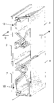
FIGURE 1 is a fragmented side perspective view of a pair of track
assemblies embodying the present invention, and supporting a fabric
therebetween;
FIGURE 2 is a cross-sectional view similarto FIG. 1, but illustrating
an insulated or acoustical panel between the track assemblies;
FABRIC-48089
PCT APP
CA 02582569 2007-04-02
WO 2006/041722 PCT/US2005/035178
-6-
FIGURE 3 is a perspective view of a base track affixed to a surface,
and an upper track positioned for attachment thereto;
FIGURE 4 is a cross-sectional view taken generally along line 4-4
of FIG. 3;
FIGURE 5 is a cross-sectional view similarto FIG. 4, but illustrating
the closing of the hinge assembly to secure fabric therein;
FIGURE 6 is a cross-sectional view taken generally along line 6-6
of FIG. 1, illustrating a track assembly in a closed state and securing
fabric;
FIGURE 7 is a cross-sectional view similarto FIG. 6, but illustrating
a beveied configuration;
FIGURE 8 is a cross-sectional view similarto FIG. 6, but illustrating
a bull-nosed configuration;
FIGURE 9 is a cross-sectional view similarto FIG. 6, but illustrating
a one-half inch system;
FIGURE 10 is a cross-sectional view similar to FIG. 9, but
illustrating a bull-nosed configuration;
FIGURE 11 is a cross-sectional view similar to FIG. 9, but
illustrating a beveled configuration;
FIGURE 12 is a cross-sectional view illustrating another track
assembly embodying the present assembly for creating a seam between two
pieces of fabric;
FIGURE 13 is a cross-sectional view of another track assembly
embodying the present invention;
FIGURE 14 is a cross-sectional view illustrating yet another
embodiment of the track assembly of the present invention;
FIGURE 15 is a cross-sectional view illustrating yet another
embodiment of the track assembly; and
FIGURE 16 is a cross-sectional view of yet another embodiment of
the present invention.
FABRIC-48089
PCT APP
CA 02582569 2007-04-02
WO 2006/041722 PCT/US2005/035178
-7-
DETAILED DESCRIPTION OF THE PREFERRED EMBODIMENTS
As shown in the accompanying drawings for purposes of illustration,
the present invention resides in a track assembly for covering walls with a
fabric or the like. As discussed above, very tight tensioning of fabric panels
can impose very high loads on the relatively light-weight hinge and track
assembly structures. The spans of fabrics to be stretched can exceed thirty
by twenty-five feet, and the fabric panels alone can weigh fifty pounds or
more. In the prior art, there was a continuing concern that the fabric could
become dislodged from the track assembly due to the tension exerted
thereon by the stretched fabrics. Certain track assemblies, particularly those
of approximately one-inch thickness, having a generally rectangular closed
configuration, could be deformed and moved into a generally parallelogram
shape due to the high tension forces of the stretched fabric. As will be more
fully described herein, the track assembly of the present invention discloses
a design incorporating a strut and a high tension dissipater which
accommodates these high tension forces, even in a one-inch thick assembly.
With reference now to FIGS. 1 and 2, there is shown a surface 2,
such as a wall, which is partly broken away, and includes a fabric covering
4 supported by a framework made up of the track assemblies 10 and 12,
respectively. In the embodiments illustrated in FIGS. 1-8, the track
assemblies are approximately one-inch in thickness so as to accommodate
insulative or acoustical panels 6, which as described above, can be
comprised of fiberglass, fiber board, or other appropriate material. As
illustrated in FIGS. 1 and 2, the track assemblies 10 and 12 serve to stretch
the fabric 4 over a portion of the wall 2 or other surface.
With reference now to FIGS. 3-6, the assembly is comprised of a
base track 100 and an upper track 102 which are pivotally connectable to
one another and selectively interlocked. The base track 100 includes a
generally flat base plate 104 which contacts the wall 2. The base track 100
is attached to the wail 2, such by nails, adhesive, or the like. Although the
assemblies are shown fragmented in FIGS. 1-3, it will be appreciated by
FABRIC-48089
PCT APP
CA 02582569 2007-04-02
WO 2006/041722 PCT/US2005/035178
-8-
those skilled in the art that the base and upper tracks 100 and 102 are
typically several feet in length necessary to support the fabric, or are sold
in
smaller segments which are abutted end to end to accommodate the width
or length of the fabric. Preferably, the base track 100 and upper track 102
are molded and comprised of an ABS plastic, such as HB-8054, which is a
non-flammable additive, so as to have a Class A rating for flame spread and
smoke production. Many prior track assemblies are comprised of PVC,
which, when exposed to flames, emits high levels of smoke as well as
chlorine gas.
With continuing reference to FIGS. 3-6, the base track 100 defines
a first half of a hinge 106 defining a channel 108. Typically, the hinge
portion
106 has a generally C-shape or e-shape, although it is not limited to such.
Typically, the hinge portion 106 is slightly off-set inwardly from the edge of
the lower base plate 104, as will be described more fully herein. The C-
shape of the hinge turns and extends inwardly such that it acts as a guide for
rotation for a mating hinge member, as will be more fully discussed herein.
The curved extension also assists in the locking of the opposite hinge
member, as compared to prior art designs.
Generally opposite the hinge portion 106, and typically defining the
opposite longitudinal edge, is the first half of a snapping clamp 110. The
snapping clamp includes a hook or catch 112 that extends upwardly from the
base plate 104 and wall 2.
The base track 100 of the present invention includes a tension force
dissipater. As illustrated, in a particularly preferred embodiment, the hinge
portion 106 is elevated or extends away from the base plate 104 of the base
track 100. Segments or legs 114 or 116 extend from the first half of the
hinge 106 to the base plate portions 104. Such an arrangement typically
forms a generally inverted V-shape. These segments 114 and 116 forming
a dissipater, will be more fully described herein.
With reference to FIGS. 3 and 4, the assembly 10 also includes the
upper track 102, which as previously described, cooperates with the base
track 100 to form the assembly 10 and lock the fabric 4 tightly into place.
FABRIC-48089
PCT APP
CA 02582569 2007-04-02
WO 2006/041722 PCT/US2005/035178
-9-
The upper track 102 includes a second hinged portion 118, which is
configured such so as to be inserted into the channel 108 of the first hinge
portion 106 of the base track 100, and thus forms a hinge and pivotal
connection between the base track 100 and the upper track 102, as
illustrated in FIG. 5. Generally opposite the second hinge half 118 is formed
the second half of the snapping clamp 120 which includes a hook or catch
122 which is intended to engage with the hook or catch 112 of the base track
100 to form a releasably snapping clamp. The upper track 102 has what is
referred to herein as an upper plate 124 which extends between the hinge
portion 118 and the clamp portion 120. In the illustrated embodiments of
FIGS. 1, and 3-6, the configuration or profile of the upper track 102 is
referred to in the industry as square, due to the approximately 90 angle
formed in the upper plate 124 to the snapping clamp portion 120. This
configuration results in a generally square edge in the final fabric panel
edges.
In a particularly preferred embodiment, as illustrated in FIGS. 4-6,
the upper plate 124 includes a tab 128 extending upwardly therefrom a
fraction of an inch. The tab 128 is designed and sized so as to enable the
fabric 4 to rise slightly above the parallel mounting surface of the upper
plate
124 so as to minimize the reflection of light from the extrusion and resultant
shadow box effect encountered with prior art assemblies. As will be
appreciated by those skilled in the art, the fabric is typically positioned
and
aligned with alignment tape, such as double-sided tape toward the snapping-
clamp portion of the track assembly. Although not required, this is preferred
as it holds the fabric 4 onto the upper plate 124 of the upper track 102,
allowing a free end of the fabric to be inserted between the tracks 100 and
102 and clamped into place tightly.
The manner in which the first and second base track 100 and upper
track 102 cooperate to facilitate the stretching and securing of the fabric 4,
will now be evidenced by referring to FIGS. 5 and 6. The base track 100 is
typically secured to the wall or other surface, such as with screws, nails,
etc.
The design of the base track 100 of the present invention provides access
FABRIC-48089
PCT APP
CA 02582569 2007-04-02
WO 2006/041722 PCT/US2005/035178
-10-
by various pneumatic and other tools for fastening purposes. Referring first
to FIG. 5, the hinge portions 106 and 118 of the tracks 100 and 102 are
operably joined together by inserting the second hinge portion of 118 into the
channel 108 of the first hinge portion 106 such that a pivotal relationship is
created between the tracks 100 and 102. The fabric 4 is then dropped over
upper track 102 and the upper track moved toward the base track 100 until
the hook and catch portions 112 and 122 or the clamping portions 110 and
120 engage with one another, securely locking the fabric 4 therebetween, as
illustrated in FIG. 6. The result is a very tensioned and tight fabric
extending
between the assembly 10 as illustrated in FIGS. 1 and 6.
As discussed above, particularly in one-inch systems, the tension
of the fabric 4 exerts a tremendous amount of force on the assembly 10, and
particularly on the upper track 102, which force can cause the hinge
assembly to flex rearward and fail, or the overall assembly 10 could be
deformed and moved into a generally parallelogram shape. The present
invention overcomes this problem with the addition of a strut 126, which
extends downwardly towards the base track 100. As illustrated in FIGS. 3-6,
the strut 126 is angled downwardly towards the hinge and dissipater of the
assembly 10. The result is that if excessive tension forces are present, and
the upper track 102 begins to be pulled rearwardly, the strut 126 will engage
the base track 100 to transmit the tension forces into the base track 100, and
thus into the surface of the wall 2. In a particularly preferred embodiment,
the strut 126 is configured such so as to be moved into contact with the hinge
portion 106 of the base track 100 such that the forces are transmitted to the
elevated segments 114 and 116 of the tension force dissipater so that they
are transmitted through the segments 114 and 116 to the base plate 104 and
wall 2. Due to the transmission of these forces and the contact between the
strut 126 and the base plate 100, the upper plate 102 remains in place and
the fabric 4 remains tight. Moreover, the assembly 10 retains its generally
square configuration and resists deforming.
With reference now to FIGS. 7 and 8, although the invention has
been described above with respect to a square configuration or profile, it
will
FABRIC-48089
PCT APP
CA 02582569 2007-04-02
WO 2006/041722 PCT/US2005/035178
-11-
be readily understood by those skilled in the art in the profile can be
readily
adapted. For example, in FIG. 7, assembly 12 is illustrated wherein the base
track 100 is of the same configuration, but the upper plate 124' of the upper
track 102' has an angled or beveled configuration and profile, which is
sometimes desirable.
FIG. 8 is yet another assembly 14, embodying the present
invention, wherein the base track 100 and its component parts are as
described above, but the upper track 102" has an upper plate 124" having a
sloping or configuration known in the art as a bull-nose profile. Otherwise,
these assemblies 12 and 14 function in the same manner as described
above.
With reference nowto FIGS. 9-11, although a one-inch thick system
has been illustrated and described above, the present invention can be
incorporated into other sizes as well, such as the illustrated one-half inch
assemblies 16-20. However, the structure and function of the assemblies 16-
20 are as described above, thus similar reference numbers have been used
to identify similar structure in these embodiments 16-20.
With reference now to FIG. 12, a seam can be formed between to
pieces of fabric 4 and 4' by positioning two track assemblies in close
proximity to one another and clamping the fabric 4 and 4' within the
respective snapping clamps. Alternatively, as illustrated in FIG. 12, the two
track assemblies may be constructed so as to share a common base track
200. The base track 200 would.include opposite hinge portions 206 with
tension force dissipaters 214 and 216 and a generally planar base plate 204
extending therebetween. Hooks or catches 212 would be spaced apart from
one another and extend upwardly from the base plate 204 so as to form a
snapping clamp with the diametrically opposed upper tracks 202. As
illustrated, the two upper tracks 202 would each support a separate piece of
fabric 4 and 4' and be swung towards one another and interlocked with the
base track 200. Forces exerled on the assembly 22 would be handled in the
same manner as that described above with the use of the strut 226 and
dissipater 214, 216. Thus, tight seems can be formed between two pieces
FABRIC-48089
PCT APP
CA 02582569 2007-04-02
WO 2006/041722 PCT/US2005/035178
-12-
of fabric 4 and 4' without the need to carefully reposition the assemblies
relative to one another.
With reference now to FIG. 13, yet another track assembly 24
embodying the present invention is illustrated. This embodiment 24 is very
similar to the embodiment 10 illustrated and described above with respect to
FIGS. 4-6. As such, the assembly 24 includes a base track 300 having a
base plate 304, a first hinge portion 306, and a first snapping clamp portion
310. A tension force dissipater 314 and 316 elevated with respect to the
base plate 304, and once again extending from the hinge portion 306 is also
formed as part of the base track 300. The upper track 302 includes the
second hinge portion 318, which operably mates with the first portion 306 to
form the hinge, the upper plate 324 (which in this case is a square profile,
but
it will be readily appreciated that other profiles are possible), which
extends
down to the second half of the snapping clamp 320. The strut 326 extends
downwardly towards the base track 300, and more particularly the second
hinge portion 306 and tension force dissipater 314 and 316. However, in this
case, a knob 330 is formed on the base track 300, and more particularly on
the first hinge portion 306, such as the strut 326 is moved into contact with
the first hinge portion 306, its rearward movement is prohibited by the knob
330.
With reference now to FIG. 14, yet another track assembly 26
embodying the present invention is illustrated. Similar to that illustrated
and
described above, the base track 400 includes a base plate 404 having
elevated sections 414 and 416 which define the tension force dissipater. The
first hinge portion 406 is preferably elevated with respect to the base plate
404 and extends from the tension force dissipater 414 and 416. A first clamp
portion 410 is formed generally opposite the hinge portion 406.
The upper track 402 includes the second hinged portion 418, which
operable engages the first hinge portion 406 to form the hinge. Generally
opposite this is formed the second snapping clamp half 420, which operably
engages and interlocks with the first clamping half 410 of the base track 400.
In this case, the upper plate 424 has a bull-nose profile, although others are
FABRIC-48089
PCT APP
CA 02582569 2007-04-02
WO 2006/041722 PCT/US2005/035178
-13-
contemplated. In this assembly 26, the strut 426 of the upper track 402 does
not extend downwardly at an angle towards the hinge, but rather extends
downwardly in front of the hinge 406 and 418. When excessive forces are
applied to the upper track 402, the strut 426 is moved laterally into
engagement with the lower hinge half 406, which transmits at least a portion
of the tension forces through segments 414 and 416 to the base plate 404
and thus the surface or wall 2.
With reference now to FIG. 15, yet another embodiment of the
present invention is illustrated wherein the assembly 28 is similar to that
described above, in the sense that it includes a base track 500 and an upper
track 502 which are pivotally connected to one another and capable of being
interlocked so as tension fabric 4. In this case, however, segments 514 and
516 forming the tension force dissipater extend upwardly from a continuous
base plate 504. Segment 516 is separated slightly from the first hinge half
506. In this case, the first hinge half 506 is semi-circular so as to include
a
slot or key way 530. The second hinge portion 518 of the upper track 502
includes a tab or key 532 so as to be configured such so as to be received
within the key way 530 when the assembly 28 is in a closed and locked
position, as illustrated. The second portion of the hinge 518 is also semi-
circular and extends around the first half of the hinge 506. The strut 526
extends from the upper plate 524 to the second hinge member 518. When
excessive fabric tension forces are present, the strut 526 and second portion
of hinge 518 engage the first portion of the hinge 506, causing it to transfer
the forces into the base plate 504. In extreme cases, the hinge 506 is moved
into contact with segment 516 to further transfer the forces into the base
plate and wall surface 2.
With respect to the hinge 506 and 518, the larger hinge member is
slightly heavier and exceeds 220 in circumference, enabling it to be
removed and replaced over the inner hinge 506, which, because of the slot
or key way 530, flexes as the outer second hinge half 518 is snapped into
place and closed. When mated, the hinge assembly 506 and 518 can rotate
from a full open (0 angle, to a fully closed and locked position at 90 , as
FABRIC-48089
PCT APP
CA 02582569 2007-04-02
WO 2006/041722 PCT/US2005/035178
-14-
illustrated). When in the full open position, the outer hinge portion 518
rotates on the inner hinge portion 506. As it rotates and is closed into a
locked position, the tab or the tab 532 drops into the key way opening 530,
allowing the entire outer portion 518 to shift laterally. This lateral shift
assists
the assembly 28 to securely lock the fabric 4 into place.
With reference now to FIG. 16, similar to that as described above,
the assembly 30 includes a base track 600 and an upper track 602, which
operably lock and tension fabric. The base track 600 includes a generally
planar base plate 604 having a first hinge half 606 formed on one end thereof
and a first snapping tab portion 612 formed on an opposite end thereof.
The first hinge half 606 is formed in a generally C-shape, so as to
removably receive a second hinge half portion 618 of the upper track
assembly 602 therein to form pivotal engagement between the track 600 and
602. The upwardly extending catch 612 engages a downwardly directed
hook 622 of the upper track 622. Serrations 630 frictionally engage the hook
and catch 622 and 612 to one another. Fabric can be extended around an
inner hook 632 to further hold the fabric therein.
In this case, the strut 626 extends downwardly towards the base
track 600, and particularly the first half of the hinge 60. It will be noted,
that
the first half of the hinge 606 is not elevated with respect to the base plate
604, and thus does not have upwardly extending segments defining the
tension force dissipater of the previous embodiments. Instead, when
experiencing excessive tension forces by the tensioned fabric, the strut 626
moves into engagement with the base track 600, and in this case the hinge
member 606 of the base track 600 so as to prevent the upper track 602 from
excessive movement and deformation while transmitting a portion of the
tension forces into the base track 600, and thus the wall surface 2. Once
again, a tab 628 can be used to prevent shadow effects, similar to that
described above.
The track assemblies of the present invention are produced in
common architectural designs prevalent in wall upholstery track systems.
The assemblies enable the taut installation of fabric or vinyl on the wall or
FABRIC-48089
PCT APP
CA 02582569 2007-04-02
WO 2006/041722 PCT/US2005/035178
-15-
acoustical panels, which can be removed in the future for decoration or
equipment access changes and the like without the need to replace the entire
panel. Thus, the present invention provides a significant cost savings to end
users. The forces applied by fabric are directed into the asserrmbled hinge
and cannot escape. The assemblies are designed so as to minimize any
shadow effects, and prevent the outer memberfrom popping out when under
increasing tension as it is rotated and closed. The assemblies of the present
invention also enable the installers to more easily open and close the
assemblies without resorting to excessive pounding with mallets and the like.
Although several embodiments have been described in detail for
purposes of illustration, various modifications may be made to each without
departing from the scope and spirit of the invention. Accordingly, the
invention is not to be limited, except as by the appended claims.
FABRIC-48089
PCT APP