Language selection

Search

Patent 2582853 Summary

Third-party information liability

Some of the information on this Web page has been provided by external sources. The Government of Canada is not responsible for the accuracy, reliability or currency of the information supplied by external sources. Users wishing to rely upon this information should consult directly with the source of the information. Content provided by external sources is not subject to official languages, privacy and accessibility requirements.

Claims and Abstract availability

Any discrepancies in the text and image of the Claims and Abstract are due to differing posting times. Text of the Claims and Abstract are posted:

  • At the time the application is open to public inspection;
  • At the time of issue of the patent (grant).
(12) Patent Application: (11) CA 2582853
(54) English Title: BRACING SYSTEM FOR CANVAS STRETCHER FRAMES
(54) French Title: SYSTEME D'ENTRETOISEMENT POUR FAUX CADRES A TOILES
Status: Deemed Abandoned and Beyond the Period of Reinstatement - Pending Response to Notice of Disregarded Communication
Bibliographic Data
(51) International Patent Classification (IPC):
  • B44D 3/18 (2006.01)
  • D06C 3/08 (2006.01)
(72) Inventors :
  • VAZ, PAUL (Canada)
(73) Owners :
  • ARTEX PICTURE FRAMES LTD.
(71) Applicants :
  • ARTEX PICTURE FRAMES LTD. (Canada)
(74) Agent: R. WILLIAM WRAY & ASSOCIATES
(74) Associate agent:
(45) Issued:
(22) Filed Date: 2007-03-27
(41) Open to Public Inspection: 2008-09-27
Availability of licence: N/A
Dedicated to the Public: N/A
(25) Language of filing: English

Patent Cooperation Treaty (PCT): No

(30) Application Priority Data: None

Abstracts

English Abstract


The present invention relates to the stretching of canvas or other flexible
materials on a stretching frame to be displayed without the use of a frame.
This
invention is designed to be sold as a kit which can be assembled by an
unskilled end
user without the use of stretching pliers and staplers (which require
considerable
strength and skill). The present invention allows for the tucking of the
corner folds of
canvas inside the mitered corners for a neater result than then the standard
stretching
systems available today. The finished product will have no side edge
fasteners,
unsightly corner folds or wrinkles.


Claims

Note: Claims are shown in the official language in which they were submitted.

6
CLAIMS
The embodiments of the invention in which an exclusive property or privilege
is
claimed are defined as follow:
1. A stretching kit including a set of parts comprising:
(a) four stretcher bars adhered onto a flexible material with notched corners
forming a rectangle. The stretchers are pre aligned and adhered in such a
manner that they can be rotated 90 deg axially along the inner edge closest to
the flexible material. This results in a closed frame with all the miters
meeting;
(b) a special purpose double sided tape affixed to the outer edges of the
flexible material opposite the stretcher bars to adhere the canvas to the
stretching kit;
(c) a special purpose double sided tape affixed to the miters which allows for
the canvas corners to be fastened to the said miters once the canvas corners
are
cut;
(d) a U shape fastener which is hand inserted into purpose built grooves on
the
stretcher bar ends to keep the stretching frame closed in its final position;
(e) a perforated rectangular outline on the material to which the stretchers
are
adhered which can be removed once the canvas has been mounted to allow for
the canvas to breathe from both sides;
(f) wedge shaped inserts which can be used to separate the miters and increase
the canvas tension;

7
(g) a groove in the middle of each stretcher running parallel to the miters to
allow for easy hanging or the insertion of a cross brace with end tenons.

Description

Note: Descriptions are shown in the official language in which they were submitted.


CA 02582853 2007-03-27
1
BRACING SYSTEM FOR CANVAS STRETCHER FRAMES
FIELD OF INVENTION
This invention concerns canvas stretching frames, and particularly a bracing
system for use by novice framers.
BACKGROUND OF THE INVENTION
Most prior art stretchers are manufactured as standard dimension lengths with
machined ends. These lengths are assembled into frames with interlocking
corners.
The canvas or material is stretched on this frame using stretching pliers and
with
staples on the side. Wedges can be inserted into the interlocking corner.s to
expand the
frame and tension the canvas. This embodiment of the product has been around
for a
long time and works well, however stretcher bars of this type have a few
disadvantages:
= When first assembled the stretchers must be squared and aligned by the
user or the diagonals will be off making subsequent framing difficult or
impossible.
= The stretching of the material on the stretchers requires the use of
specific
tools like stretching pliers and staple guns both of which are costly and
might not be available in the average consumers household.
= The above mentioned stretching system requires a fair amount of skill,
strength and practice in order to get good results thus it is intimidating and
not user friendly.
= In this type of stretching the staples are normally placed on the side of
the
stretchers which makes the side edges of the canvas unsightly.
= The corners of the material must be folded and fastened on the sides
adding bulk and detracting further from the edge appearance of the
finished product.
= The sophisticated nature of the machined ends of the above mentioned
stretchers do not allow for resizing and therefore cannot be used if the

CA 02582853 2007-03-27
2
dimensions of the art work to be stretched does not fall within the standard
sizes currently being manufactured.
= Currently available stretchers allow for expansion with the use of wedge
inserts into the interlocking corners. These inserts however are often
missing from the corners making it impossible to retighten the corners
without them.
SUMMARY OF THE INVENTION
The present invention relates to the stretching of canvas or other flexible
materials on a stretching frame to be displayed without the use of a frame.
This
invention is designed to be sold as a kit which can be assembled by an
unskilled end
user without the use of stretchina pliers and staplers (which require
considerable
strength and skill). The present invention allows for the tucking of the
corner folds of
canvas inside the mitered corners for a neater result than then the standard
stretching
systems available today. The finished product will have no side edge
fasteners,
unsightly corner folds or wrinkles.
The present invention provides four stretcher bars mitered at both ends which
are adhered to a flexible rectangular material. The stretcher bars are
fastened to said
material in such a manner that when rotated axially by 90 deg the mitered
corners
meet to form a closed frame.
A unique feature of the present invention is the use of double sided tape to
adhere the canvas to the stretcher bar kit. This is accomplished by allowing
the user to
adhere the canvas to the stretcher bar kit while it is in the open position.
The canvas is
stretched by the rotation of the stretcher bars 90 deg into the final
position.
The present invention also deals with the corners of the canvas by allowing
the
user to fold the canvas into the miters before the frame is rotated into the
final and
closed frame.
At each mitered corner two grooves are provided which run perpendicular to
the length of the bars. A "U" shaped fastener is inserted into these groves to
keep the

CA 02582853 2007-03-27
3
miters from separating.
This invention allow the user to take a canvas and apply it to a stretching
frame where the only tool need is a pair of scissors.
BRIEF DISCRIPTION OF DRAWINGS
FIG 1. is an elevation view of the basic stretcher element.
FIG 2. is an elevation view of the U shaped fastener.
FIG 3. is an elevation view of wedge to increase canvas tension.
FIG 4. is an elevation view of the double sided tape.
FIG 5. is an elevation view of the material to which the stretcher bars and
the double
sided tape is affixed.
FIG 6. is an exploded view of all elements of stretching kit.
FIG 7. is an elevation view of the kit as supplied before attaching of canvas.
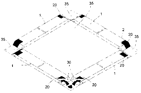
FIG 8. is an isometric view of the kit on the canvas showing the cutting of
the corners
of the canvas and the adhering of the corners to the stretcher bar miters.
FIG 9. is an isometric view of the folding of the kit into the final position
along with
the insertion of the U shaped fasteners.
FIG 10. is an elevation view of the finished product with the wedge inserts.
DESCRIPTION OF PREFERED EMBODIMENTS
FIG 1. shows the elevation of basic stretcher bar 1. Each bar has a miter at
each end 2 as well a groove 3 running parallel to the miter 2. Each stretcher
bar will

CA 02582853 2007-03-27
4
also have a groove 4 located in the center of the longitudinal axis running
parallel to
the mitered ends 2.
FIG 2. shows the elevation of U shaped fastener 5 which is inserted by hand to
keep the stretching frame closed.
FIG 3. shows the elevation of a wedge to be inserted into the closed frame
miters from the inside to increase canvas tension.
FIG 4. shows the elevation to the double sided tape 20. This tape is
formulated
to adhere wood as well as to canvas. The tape 20 has an adhesive substrate
covered
by strips of release paper to be removed only when the tape is to be used.
This
adhesive must have good tack as well as creep resistance.
FIG 5. shows the elevation of the flexible material 6 to which the stretcher
bars 1 will be adhered. The corners 7 are notched to allow the stretcher bars
to bend
along line 8 and meet without the interference of the material from the
corners. The
material 6 is creased along line 8 to allow for easy bending. There is a
perforated
rectangle 10 close to crease lines 8. Once the stretching frame is assembled
the user is
to pull on tab 9 and remove the rectangle 11 defined by the perforations 10.
The
removal of rectangle 11 will allow the canvas to breathe from both sides.
Material 6 must be stiff strong, thin and resist tearing. The material 6 must
be
able to be folded at least 90 deg. without breaking.
FIG 6 shows the exploded view of the prefabricated kit. The stretcher bars are
adhered onto material 6 using strips of adhesive 20a or other methods of
permanent
fastening. Strips of adhesive 20 b are installed onto material 6 on the canvas
side and
wrapped around onto miters 2. These strips of double sided tape 20 b are left
with the
release paper to be removed by the user when the canvas is to be mounted.
FIG 7 shows the embodiment of the finished kit. The stretcher bars 1 are pre-
positioned and glued on to material 6 in such a way that they will form a
closed

CA 02582853 2007-03-27
frame upon being rotated into their final position (once the canvas is
installed). The
adhesive tape 20 is placed along the outer periphery of the kit and wrapped
around
each miter 2 to allow for the adhesion of the canvas and the canvas corners
inside the
miters before closing the stretching frame.
FIG 8. shows the stretching kit positioned over the canvas 35. The adhesive
covers have been removed of the double sided tape 20 and the stretching kit is
attached to the canvas 35. The corners of the canvas 36 are cut and adhered to
the
inside of the miters 2.
FIG 9. shows the stretchers 1 being rotated into their final position with the
U
shaped fasteners 5 being inserted into grooves 3. U Shaped fasteners must be
able to
counteract the tension of the canvas and maintain the stretching frame in its
closed
position.
FIG 10. shows the elevation of the closed stretcher frame once the canvas 30
has been mounted. The U shaped fasteners 5 are fully inserted. Wedges 12 are
inserted into the closed miters from the inside and placed closest to the
canvas as to
allow for an increase in canvas tension if it is required.
Groove 4 is to be used to center the piece when it is be to hung on a nail.

Representative Drawing
A single figure which represents the drawing illustrating the invention.
Administrative Status

2024-08-01:As part of the Next Generation Patents (NGP) transition, the Canadian Patents Database (CPD) now contains a more detailed Event History, which replicates the Event Log of our new back-office solution.

Please note that "Inactive:" events refers to events no longer in use in our new back-office solution.

For a clearer understanding of the status of the application/patent presented on this page, the site Disclaimer , as well as the definitions for Patent , Event History , Maintenance Fee  and Payment History  should be consulted.

Event History

Description Date
Application Not Reinstated by Deadline 2011-03-28
Time Limit for Reversal Expired 2011-03-28
Deemed Abandoned - Failure to Respond to Maintenance Fee Notice 2010-03-29
Application Published (Open to Public Inspection) 2008-09-27
Inactive: Cover page published 2008-09-26
Inactive: IPC assigned 2007-11-23
Inactive: First IPC assigned 2007-11-23
Letter Sent 2007-08-16
Inactive: Single transfer 2007-06-13
Inactive: Courtesy letter - Evidence 2007-05-01
Inactive: Filing certificate - No RFE (English) 2007-04-27
Filing Requirements Determined Compliant 2007-04-27
Application Received - Regular National 2007-04-25
Small Entity Declaration Determined Compliant 2007-03-27

Abandonment History

Abandonment Date Reason Reinstatement Date
2010-03-29

Maintenance Fee

The last payment was received on 2009-03-26

Note : If the full payment has not been received on or before the date indicated, a further fee may be required which may be one of the following

  • the reinstatement fee;
  • the late payment fee; or
  • additional fee to reverse deemed expiry.

Please refer to the CIPO Patent Fees web page to see all current fee amounts.

Fee History

Fee Type Anniversary Year Due Date Paid Date
Application fee - small 2007-03-27
Registration of a document 2007-06-13
MF (application, 2nd anniv.) - small 02 2009-03-27 2009-03-26
Owners on Record

Note: Records showing the ownership history in alphabetical order.

Current Owners on Record
ARTEX PICTURE FRAMES LTD.
Past Owners on Record
PAUL VAZ
Past Owners that do not appear in the "Owners on Record" listing will appear in other documentation within the application.
Documents

To view selected files, please enter reCAPTCHA code :


To view images, click a link in the Document Description column. To download the documents, select one or more checkboxes in the first column and then click the "Download Selected in PDF format (Zip Archive)" or the "Download Selected as Single PDF" button.

List of published and non-published patent-specific documents on the CPD .

If you have any difficulty accessing content, you can call the Client Service Centre at 1-866-997-1936 or send them an e-mail at CIPO Client Service Centre.


Document
Description 
Date
(yyyy-mm-dd) 
Number of pages   Size of Image (KB) 
Description 2007-03-27 5 186
Abstract 2007-03-27 1 16
Claims 2007-03-27 2 37
Drawings 2007-03-27 3 73
Representative drawing 2008-09-03 1 13
Cover Page 2008-09-12 1 40
Filing Certificate (English) 2007-04-27 1 158
Courtesy - Certificate of registration (related document(s)) 2007-08-16 1 104
Reminder of maintenance fee due 2008-12-01 1 112
Courtesy - Abandonment Letter (Maintenance Fee) 2010-05-25 1 173
Correspondence 2007-04-27 1 26
Correspondence 2007-06-13 2 49
Fees 2009-03-26 1 40