Note: Descriptions are shown in the official language in which they were submitted.
CA 02583164 2007-03-22
WO 2005/032640 PCT/US2004/028840
PERCUTANEOUS ENDOSCOPIC GASTROSTOMY TUBE HOLDER
FIELD OF INVENTION
[0001] The present invention relates generally to an apparatus in the field of
gastrointestinal therapy and more particularly to an apparatus for protecting
a Percutaneous
Endoscopic Gastrotomy (PEG) tube and stoma when fitted to a recipient.
BACKGROUIVD OF THE INVENTION
[0002] Previous apparatuses have been developed for securing medical tubes in
direct
contact with a recipient's skin. These apparatuses may use an adhesive, which
may be
hypoallergenic, to affix the holding apparatus to the recipient's skin. In
addition, the apparatuses
must be secured around the tube itself. Some of these apparatuses hold a tube
by applying an
adhesive portion of the apparatus directly to the tube. Other apparatuses hold
a tube by adhering
opposing sides of the apparatus.
[0003] Applying an adhesive portion of a holding apparatus to a tube has
numerous
disadvantages. For instance, by directly adhering the tube to the holder, the
range of movement
of the tube may be limited. Furthermore, if medical personnel desire to remove
the tube from the
holder, the tube must first be removed from the adhesive portion of the
holder. This may cause
stress and damage to the tube. In addition, the adhesive portion of the holder
may lose some of
its adhesiveness each time the tube is removed from the holder causing the
holder to lose the
ability to securely hold a tube over time.
[0004] What is needed is a medical tube holding apparatus that allows the tube
to be
secured to a recipient and to the tube in such a manner that removal of the
tube from the holder
does not cause damage to the tube. Furthermore, a PEG tube holding apparatus
is needed that
allows the tube to have a range of motion within the holder so that a
recipient may not be
1
CA 02583164 2007-03-22
WO 2005/032640 PCT/US2004/028840
restricted in his or her movement. Moreover, the PEG tube holding apparatus
must be able to be
produced at a low cost.
SUMMARY OF THE INVENTION
[0005] The present invention is directed to solving one or more of the
aforementioned
problems.
[0006] In a preferred embodiment of the present invention, an apparatus for
holding a
percutaneous endoscopic gastrotomy (PEG) tube includes a front side and a back
side. The front
side includes a left section, a middle section, and a right section. The left
and right sections each
have a surface at least partially covered by a refastenable material, such as
VELCRO . The
middle section has a surface including a first material. In an embodiment, the
first material is
cotton. The first material may cover substantially all of the middle section.
[0007] The back side includes an adhesive section and a non-adhesive section.
The
adhesive section has a surface at least partially covered by a hypoallergenic
adhesive. In a
preferred embodiment, a protective cover covers the hypoallergenic adhesive.
The
hypoallergenic adhesive may cover substantially all of the surface of the
adhesive section.
Alternately, the hypoallergenic adhesive is aligned in one or more strips on
the surface of the
adhesive section. The non-adhesive section has a surface including a second
material. In an
embodiment, the second material is cotton. The second material may cover
substantially all of
the non-adhesive section.
[0008] In a preferred embodiment, the apparatus has a notch removed from a
first
portion of the non-adhesive section and the one or more sections of the front
side opposed to the
first portion of the non-adhesive section.
[0009] In a preferred embodiment, a method of applying a PEG holder to a
recipient in
order to hold a PEG tube includes first adhering the PEG holder to the
recipient. The PEG holder
2
CA 02583164 2007-03-22
WO 2005/032640 PCT/US2004/028840
includes a front side and a back side. The front side includes a left section,
a middle section, and
a right section. The left and right sections each have a surface at least
partially covered by a
refastenable material. The back side has a surface partially covered by a
hypoallergenic adhesive
for adhering the PEG holder to the recipient. The method also includes placing
the PEG tube in
the middle section and affixing the refastenable material of the left section
to the refastenable
material of the right section. In an embodiment, the method further includes
removing a
protective cover covering the hypoallergenic adhesive before adhering the PEG
holder to the
recipient. In an embodiment, placing the PEG tube includes aligning the PEG
tube such that a
receiving end of the PEG tube extends substantially vertically upward.
[0010] In a preferred embodiment, a method of removing a PEG tube from a PEG
holder attached to a recipient includes first unfastening a PEG holder. The
PEG holder includes a
front side and a back side. The front side includes a left section, a middle
section, and a right
section. The left and right section each have a refastenable material. The
back side includes a
surface that is partially covered by a hypoallergenic adhesive. The back side
is initially adhered
to a recipient. Unfastening the PEG holder includes unfastening the left
section of the PEG
holder from the right section of the PEG holder. The method also includes
removing the PEG
tube from the middle section. In an embodiment, the method further includes
removing the back
side of the PEG holder from the recipient.
[0011] This apparatus provides several advantages, including an increase in
patient
comfort and an increase in the reliability and lifespan of a PEG tube as it is
less likely to be
compromised. In addition, a higher level of medical care may result an enable
stoma health.
Another advantage of the tube holder is that it may be manufactured from
readily available
materials, utilizing common manufacturing technologies and techniques.
3
CA 02583164 2007-03-22
WO 2005/032640 PCT/US2004/028840
BRIEF DESCRIPTION OF THE DRAWINGS
[0012] In part, other aspects, features, benefits and advantages of the
embodiments of
the present invention will be apparent with regard to the following
description, appended claims
and accompanying drawings where:
[0013] FIG. 1 illustrates a front view of a preferred embodiment of the
present
invention.
[0014] FIG. 2 illustrates a back view of a preferred embodiment of the present
invention.
[0015] FIG. 3 illustrates a front view of an exemplary PEG holder as it
envelopes a PEG
according to an embodiment of the present invention.
[0016] FIG. 4 illustrates a front view of an exemplary embodiment of the
present
invention as attached to the body of a user and folded into an enveloped PEG
holder.
DETAILED DESCRIPTION OF THE INVENTION
[0017] Before the present compositions and methods are described, it is to be
understood that this invention is not limited to particular compositions,
methodologies or
protocols described, as these may vary. It is also to be understood that the
terminology used in
the description is for the purpose of describing the particular versions or
embodiments only, and
is not intended to limit the scope of the present invention which will be
limited only by the
appended claims.
[0018] It must also be noted that as used herein and in the appended claims,
the singular
forms "a," "an" and "the" include plural references unless the context clearly
dictates otherwise.
Thus, for example, reference to a "PEG holder" is a reference to one or more
PEG holders and
equivalents thereof known to those skilled in the art, and so forth. Unless
defined otherwise, all
4
CA 02583164 2007-03-22
WO 2005/032640 PCT/US2004/028840
technical and scientific terms used herein have the same meanings as commonly
understood by
one of ordinary skill in the art. Although any methods, devices and material
similar or equivalent
to those described herein can be used in the practice of testing of
embodiments of the present
invention, the preferred methods, devices, and materials are now described.
All publications
mentioned herein are incorporated by reference. Nothing herein is to be
construed as an
admission that the invention is not entitled to antedate such disclosure by
virtue of prior
invention.
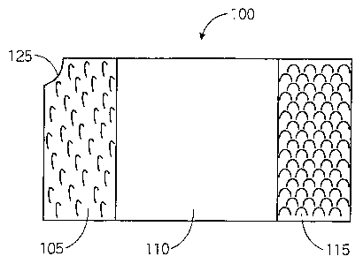
[0019] The present invention provides a PEG holder that functions as a safe
anchor for a
PEG. FIG. 1 illustrates a front side of a preferred embodiment of the present
invention. The
PEG holder 100 may be a pad with a substantially rectangular perimeter having
seamed and/or
sealed perimeter edges. In a preferred embodiment, a corner of the PEG holder
100 may have a
notch 125 cut out of it. The notch 125 may also be seamed and/or sealed. In a
preferred
embodiment, the PEG holder 100 may be approximately four inches long by
approximately two
inches wide by approximately one-eighth of an inch thick. The surface of the
front side of the
PEG holder 100 may be divided into three sections lengthwise, including a left
section 105, a
middle section 110 and a right section 115. The left section 105 and the right
section 115 may
each encompass approximately one-fourth of the length of the PEG holder 100.
Each of the left
section 105 and the right section 115 may each be covered with a material that
allows for
repetitive attachment and disengagement of the two sections, such as VELCRO .
The middle
section 110 may encompass approximately one-half of the length of the PEG
holder 100, and
may be covered in an absorbent material, such as cotton.
[0020] FIG. 2 illustrates a back side of a preferred embodiment of the present
invention.
The back side of a PEG holder 100 may also be referred to as a contact side.
The back side of
the PEG holder 100 may be sectioned in two substantially equal sized
lengthwise sections. A
non-adhesive section 205 may be covered in an absorbent material, preferably
cotton. An
CA 02583164 2007-03-22
WO 2005/032640 PCT/US2004/028840
adhesive section 210 may be at least partially covered with a hypoallergenic
adhesive. In a
preferred embodiment, the adhesive may be applied to substantially all of the
adhesive section
210. In an alternate embodiment, the adhesive may be applied in adhesive
strips in any
orientation within the adhesive section 210. Prior to adhesion to a recipient,
the adhesive section
210 may have a protective cover (not shown). Once the protective cover is
removed, the
adhesive properties may be revealed and introduced to the recipient. A corner
of the non-
adhesive section 205 may have a tab extending up from the edge.
[0021] The PEG holder 100 may ensure that a user's PEG and stoma, a surgically
created opening in the stomach in which the PEG is placed, are protected. The
PEG holder 100
may be made of a thin absorbent material, preferably cotton. The PEG holder
100 may be
reusable and inexpensive to manufacture. It may also be pre-assembled,
lightweight, portable
and comfortable for the user, ensure the health of the stoma, and protect the
condition of the
PEG.
[0022] FIGs. 3A-3C illustrate front views of an exemplary PEG holder 100 as it
is
attached for use according to an embodiment of the present invention. A
preferred method of
using the PEG holder 100 will now be described. The protective cover from the
adhesive section
210 of the back side of the PEG holder 100 may be removed. The adhesive
section 210 may be
placed against the skin of a recipient, preferably in a location near a stoma.
By pressing gently on
the front side of the PEG holder 100, the adhesive section 210 may adhere to
the skin of the
recipient, while the non-adhesive section 205 of the back side of the PEG
holder 100 may remain
free from the skin. A PEG may be placed in the middle section 110 of the front
side of the PEG
holder 100 with the PEG's valve facing substantially in a vertically upward
direction, as shown in
FIG. 3A. The tube of the PEG may be held against the middle section 110 of the
PEG holder 100
by a user while the non-adhesive section 205 is folded around the PEG, as
shown in FIG. 3B.
6
CA 02583164 2007-03-22
WO 2005/032640 PCT/US2004/028840
The non-adhesive section 205 may be pressed until the VELCROO on the left
section 105 of the
front side is coupled with the VELCROO on the right section 115, as shown in
FIG. 3C. At this
point, the PEG may be secure within the enveloping PEG holder 100.
[0023] When a user, caregiver, or health care professional needs to administer
liquid
foods or mendicants to the recipient, the PEG may be accessed by unfastening
the PEG holder
100. The PEG holder 100 may be unfastened by inserting a finger between the
left section 105
and the right section 115 of the PEG holder 100. The user may then gently pull
the non-adhesive
section 205 away from the adhesive section 210 so that the VELCROO on the left
section 105
and the right section 115 disengage. In a preferred embodiment, a notch 125 is
provided on the
non-adhesive section 205 and the opposing section or sections of the front
side to aid the
disengagement of the left section 105 from the right section 115. Once the
left section 105 and
the right section 115 are disengaged, the PEG may be removed from the middle
section 110 of
the PEG holder 100.
[0024] When removing the PEG holder 100 from the skin of a recipient, the PEG
must
first be removed as described in the preceding paragraph. The user, caregiver,
or health care
professional may then gently pull the adhesive section 210 away from the skin
until it is
disengaged.
[0025] FIGs. 4A-4C illustrate front views of an exemplary embodiment of the
present
invention as it may be attached to the body of a user and folded into the
enveloped PEG holder
form. FIGs. 4A-4C represent plausible positionings of the PEG holder 100 on
the body of a
recipient to ensure that gravitational pressure from the PEG on the stoma is
avoided. In a
preferred embodiment, the PEG valve and fluid delivery end of the PEG may be
pointed in a
substantially vertically upward direction to prevent leakage of remnant fluid
from the PEG. FIG.
4B may represent a most preferred embodiment since remnant fluid may not
gather within the
PEG.
7