Note: Descriptions are shown in the official language in which they were submitted.
CA 02583840 2007-04-11
WO 2006/089387 PCT/CA2005/000229
1
EXTENDING ACCESS TO LOCAL SOFTWARE OF A WIRELESS DEVICE
FIELD OF THE INVENTION
[0001] The present invention relates to software, devices and methods for
providing
development environments for network applications for mobile devices.
BACKGROUND OF THE INVENTION
[0002] Wireless connectivity is a feature of the modem telecommunications
environment.
An increasing range of people are using a wide variety of wireless data
networks to access
corporate data applications.
[0003] However, there are numerous competing mobile devices that can be used
to achieve
this. Each device has its own operating system and its own display
characteristics. Operating
systems are not mutually compatible, nor are the display characteristics--some
are color, some
are black and white, some are text-only, some are pictorial.
[0004] At the same time, an increasing number of mobile device users are
people without a
technical background or high level of educational achievement. Such people are
often
intimidated by the need to run complex installation programs. Furthermore, at
present, such
installation programs generally depend on cable connections to a personal
computer by the
means of a' cradle' or other such device.
[0005] As the mobile device is expanded to, for example, include new hardware
or local
software applications the server side application can typically not take
advantages of the new
hardware and software. Of course, the virtual machine software component could
be rewritten
(or recompiled). This, however, is cumbersome and would require many versions
of virtual
machine software specific to many different hardware configurations.
SUMMARY OF THE INVENTION
CA 02583840 2007-04-11
WO 2006/089387 PCT/CA2005/000229
2
[0006] Therefore, it is an object of the present invention to provide a
mechanism whereby a
mobile client for a server side application may be enabled for multiple
wireless devices with
minimal modification of the application at the server is required. a further
object of the
invention is to provide a development tools for the applications executed by
the mobile devices,
when in communication with the server side applications of backend data
sources. A further
object of the present invention is to provide for the ability to install and
upgrade the application
onto mobile devices wirelessly without the need for human intervention or
connection to PCs. A
further object of the present invention is to provide for push asynchronous
communications to
the backend data source from a variety of entities such as a middleware server
and the
development tool. It is a further object of the present invention to provide
for virtual machine
software that is extensible to communicate with local device applications.
[0007] There is provided a system for developing an application for subsequent
deployment
on a mobile device, the mobile device configured for using the deployed
application to
communicate over a network with a data source through a transaction server,
the system
comprising: an interface component module for providing access to a defined
interface
component for use in providing communication between the application and a
local software
configured to be resident on the mobile device; and a composer module for
defining a text file
containing definitions expressed in a structured definition language, the
definitions describing a
message section and a data section and a user interface section of the
application, the composer
module further for inserting handler definitions in the text file such that
the handler definitions
are configured for calling the interface component of the interface component
module.
[0008] There is further provided a method for developing an application for
subsequent
deployment on a mobile device, the mobile device configured for using the
deployed application
to communicate over a network with a data source through a transaction server,
the method
comprising the steps of: providing access to a defined interface component for
use in providing
communication between the application and a local software configured to be
resident on the
mobile device; defining a text file containing definitions expressed in a
structured definition
language, the definitions describing a message section and a data section and
a user interface
section of the application; and inserting handler definitions in the text file
such that the handler
CA 02583840 2007-04-11
WO 2006/089387 PCT/CA2005/000229
3
definitions are configured for calling the interface component of the
interface component
module.
[0009] There is further provided a computer program product for developing an
application
for subsequent deployment on a mobile device, the mobile device configured for
using the
deployed application to communicate over a network with a data source through
a transaction
server, the computer program product comprising: a computer readable medium;
an interface
component module stored on the computer readable medium for providing a
collection of
interface components for use in providing access to a defined interface
component for use in
providing communication between the application and a local software
configured to be resident
on the mobile device; and a composer module coupled to the interface component
module for
defining a text file containing definitions expressed in a structured
definition language, the
definitions describing a message section and a data section and a user
interface section of the
application, the composer module further for inserting handler definitions in
the text file such
that the handler definitions are configured for calling the interface
component of the interface
component module.
[0010] In accordance with the present invention, data from an application
executing at a
computing device is presented at a remote wireless device, by providing the
device an
application definition file, containing definitions for a user interface
format for the application at
the wireless device; the format of network messages for exchange of data
generated by the
application; and a format for storing data related to the application at the
wireless device. Using
these definitions, the wireless device may receive data from said application
in accordance with
the definition and preseilt an interface for the application.
[0011] Preferably, the application definition file is an XML file. Similarly,
application
specific network messages provided to the device are also formed using XML.
[0012] In the preferred embodiment, the data from the application is presented
at the mobile
device by virtual machine software that uses the application definition file.
CA 02583840 2007-04-11
WO 2006/089387 PCT/CA2005/000229
4
[0013] In accordance with an aspect of the present invention, a method of
presenting data
from an application executing at a computing device at a remote wireless
device, includes:
receiving at the wireless device, a representation of a text file defining: a
format of a user
interface for the application at the wireless device; format of network
messages for exchange of
data generated by the application; a format for storing data related to the
application at the
wireless device. Thereafter, data from the application may be received in
accordance with the
format of network transactions, and presented at the wireless device using the
user interface.
[0014] In accordance with another aspect of the present invention, a wireless
mobile device
includes a processor and computer readable memory in communication with the
processor,
storing virtual machine software controlling operation of the device. The
virtual machine
software includes a parser for receiving a text file; a screen generation
engine, for presenting at
least one screen at the device in accordance with the text file; an event
handler for processing
events arising in response to interaction with the at least one screen in
accordance with the text
file; and object classes corresponding to actions to be taken by the in
response to interaction with
the at least one screen.
[0015] A method of presenting data from an application executing at a
computing device at a
remote wireless device, comprising: receiving at said wireless device, a
representation of a text
file defining: a format of a user interface for the application at said
wireless device; a format of
network messages for exchange of data generated by said application; a format
for storing data
related to said application at said wireless device; receiving data from said
application in
accordance with said format of network transactions, and presenting said data
at said wireless
device using said user interface.
[0016] A wireless mobile device comprising: a processor; computer readable
memory in
communication with said processor, storing virtual machine software
controlling operation of
said device, said virtual machine software comprising: a parser for receiving
a text file; a screen
generation engine, for presenting at least one screen at said device in
accordance with said text
file; an event handler for processing events arising in response to
interaction with said at least
CA 02583840 2007-04-11
WO 2006/089387 PCT/CA2005/000229
one screen in accordance with said text file; object classes corresponding to
actions to be taken
by said in response to interaction with said at least one screen.
[0017] A wireless mobile device comprising: a processor; computer readable
memory in
communication with said processor, storing software adapting said device to
receive a
representation of a text file defining: a format of a user interface for an
application executing at a
remote computing device, at said wireless device; a format of network messages
for exchange of
data generated by said application; a format for storing data related to said
application at said
wireless device; receive data from said application in accordance with said
format of network
transactions, and presenting said data at said wireless device using said user
interface.
BRIEF DESCRIPTION OF THE DRAWINGS
[0018] These and other features will become more apparent in the following
detailed
description of embodiments of the present invention, in which reference is
made to the appended
drawings wherein:
[0019] FIG. 1 illustrates an operating network environment for a device and an
application
design tool;
[0020] FIG. 2 schematically illustrates a middleware server of FIG. 1
including an
application definitions database;
[0021] FIG. 3 schematically illustrates the formation of application
definition files at the
middleware server of FIG. 2;
[0022] FIG. 4 schematically illustrates a mobile device including virtual
machine software of
FIG. 1;
[0023] FIG. 5 further illustrates the organization of exemplary virtual
machine software at
the mobile device of FIG. 4;
[0024] FIG. 6 illustrates the structure of example application definitions of
FIG. 1;
[0025] FIG. 7 is a further embodiment of the definitions of FIG 6;
[0026] FIG. 8 is a block diagram of the tool for developing the applications
of FIGl;
[0027] FIG 9 is an example operation of simulation of the application using
the tool of FIG
8;
[0028] FIG 10 is a block diagram of the tool architecture of Figure 8;
CA 02583840 2007-04-11
WO 2006/089387 PCT/CA2005/000229
6
[0029] FIG 11 is an example display of the simulator module of FIG 10;
[0030] FIG. 12 is a flow diagram illustrating the exchange of sample messages
passed
between a mobile device, middleware server and application server of FIG. 5;
[0031] FIGS. 13-15 illustrate steps performed at a mobile device under control
of virtual
machine software of FIG. 5;
[0032] FIG. 16 illustrates the format of messages exchanged in the message
flow of FIG. 12;
[0033] FIG. 17 illustrates a presentation of a user interface for a sample
application at a
mobile device of FIG 1;
[0034] FIG. 18 illustrates a sample portion of an application definition file
defining a user
interface illustrated in FIG. 17;
[0035] FIG. 19 illustrates the format of a message formed in accordance with
the sample
portion of an application definition file of FIG. 18;
[0036] FIG. 20A illustrates a sample portion of an application definition file
defining a local
storage at a mobile device of FIG 1;
[0037] FIG. 20B schematically illustrates local storage in accordance with
FIG. 20A;
[0038] FIG. 20C illustrates how locally stored data is updated by a sample
message in
accordance with the sample portion of an application file definition of FIG.
20A;
[0039] FIGS. 21 to 34 illustrate psuedo-code for implementing aspects of the
interfaces of
FIG 9;
[0040] FIGS. 35 illustrates steps performed at a mobile device under control
of virtual
machine software of FIG. 4;
[0041] FIGS. 36A and 36B illustrates a presentation of a user interface for a
sample
application at a mobile device of FIG 4;
[0042] FIG. 37, 38 and 39A-39B illustrate a sample portion of an application
definition file
defining a user interface illustrated in FIG. 36A and 36B; and
[0043] FIG 40 shows a block diagram of the communication between a local
software and
the virtual machine of FIG 4.
DETAILED DESCRIPTION
Network System 8
CA 02583840 2007-04-11
WO 2006/089387 PCT/CA2005/000229
7
[0044] Referring to FIG. 1, a network 8 environment is shown for a mobile
device 10 and an
application development tool 116. The devices 10 execute applications 105 (see
Figure 2)
generated by the tool 116. Further example mobile devices 30, 32 and 34 are
also illustrated in
FIG. 1. These mobile devices 30, 32 and 34 are similar to device 10 and also
store and execute a
virtual machine software 24 or other client runtime environment (see Figure
2), further described
below. The Virtual machine software 24 executes on each mobile device 10, 30,
32, 34 and can
communicate with a middleware server 44 and a data source 70 through wireless
networks 36
and 38 and network gateways 40 and 42, by way of example. The wireless
applications 105 (see
Figure 2) are provisioned on the devices 10 and operate in the virtual machine
24, for providing
interaction between the application 105 and a data source 70, as fi.irther
described below. The
data sources 70 communicate with the server 44 and the tool 116 via a defined
interface 300 over
a data network 63. The application design environment tool 116 is used to
develop and test the
operation of the applications 105 in conjunction with the defined interface
300, before the
applications 105 are deployed to the network 8, as further described below.
The network 8 can
provide the example gateways 40 and 42 as a service for data access to the
wireless networks
36,38. An example of the network gateway 40,42 is available from Broadbeam
Corporation in
association with the trademark SystemsGo!. The wireless networks 36 and 38 are
further coupled
to one or more computer data networks 63, such as the Internet and/or private
data networks.
Middleware server 44 is in turn in communication with the data network 63 that
is coupled to the
data source 70. The messaging used for network 8 communication can be via
TCP/IP over an
HTTP transport. As could be appreciated, other network protocols such as X.25
or SNA could
equally be used for this purpose. It is recognised that the devices 10 can
communicate directly
with the data sources 70 via the networks 36,38,40,42,63, or in conjunction
with the middleware
server 44 acting as a gateway between the devices 10 and data sources 70. The
following
description will demonstrate communication between the devices 10 and data
sources 70 via the
middleware server 44, by way of example only.
[0045] Referring again to Figure 1, the network system 8 comprises the mobile
communication devices 10,30,32,34, hereafter referred to using the reference
numeral 10 for the
sake of simplicity, for interacting with one or more backend data sources 70
(e.g. a schema based
service such as web service or a database that provides enterprise services
used by the
CA 02583840 2007-04-11
WO 2006/089387 PCT/CA2005/000229
8
application 105) via the wireless network 36,38. The devices 10 are devices
such as but not
limited to mobile telephones, PDAs, two-way pagers, dual-mode communication
devices. It is
recognised that the middleware server 44 and data sources 70 are linked via
the network 63 (e.g.
the Internet) and/or intranets as is known in the art. The middleware server
44 can handle
request/response messages initiated by the application 105 as well as
subscription notifications
pushed to the device 10 from the data sources 70, as desired. The middleware
server 44 can
function as a messaging server for mediating messaging between the device 10
(executing the
application(s) 105) and a backend server of the data sources 70. The
middleware server 44 can
provide for asynchronous messaging for the applications 105 and can integrate
and communicate
with the legacy back-end data sources 70. The devices 10 transmit and receive,
when in
communication with the data sources 70, messaging associated with operation of
the applications
105. The devices 10 can operate as web clients of the data sources 70 through
execution of the
applications 105 when provisioned on respective virtual machines 24 of the
devices 10.
[0046] For satisfying the appropriate messaging associated with the
applications 105, the
middleware server 44 can communicate with the data sources 70 on behalf of the
devices 10 or
the devices 10 can communicate directly (not shown) with the data sources 70.
In the case where
the devices 10 communicate directly with the data sources 70, a communication
interface 914
(similar to the interface 914 for the middleware server 44 - see Figure 9)
would be part of the
device operating system 20 and/or virtual machine 24 (see Figure 4) configured
for
communication with the interface model 300. The messaging between the devices
10 and the
data sources 70 is done through various protocols (such as but not limited to
HTTP, SQL, and
component API) for exposing relevant business logic (methods) to the
applications 105 once
provisioned on the devices 10. The applications 105 can use the business logic
of the data
sources 70 similarly to calling a method on an object (or a function). It is
recognized that the
applications 105 can be downloaded/uploaded in relation to data sources 70 via
the network
36,38,40,42,63 directly to the devices 10.
[0047] For example, the middleware server 44 can be coupled to a provisioning
server 108
and a discovery server 110 for providing a mechanism for optimized over-the-
air provisioning of
the applications 105, including capabilities for application 105 discovery
from the device 10 as
CA 02583840 2007-04-11
WO 2006/089387 PCT/CA2005/000229
9
listed in a Universal Description, Discovery and Integration (UDDI), for
example, a registry 112.
The Registry 112 is a directory service where businesses can register and
search for Web
services (or other applications 105 associated with the data sources 70), and
can be part of the
Discovery Service implemented by the server 110. The registry 112 is used for
publishing the
applications 105. The application 105 information in the registry 112 can
contain such as but not
limited to a Deployment Descriptor DD (contains information such as
application 105 name,
version, and description) as well as the location of this application 105 in
an application
repository 114. The registry 112 can provide a directory for storing
information about web
services (as provided by the data sources 70) including a directory of web
service interfaces
described by WSDL, for example. Further, UDDI as a registry 112 can be based
on Internet
standards such as but not limited to XML, HTTP, and DNS protocols.
[0048] Referring again to Figure 1, it is recognised there could be more than
one middleware
server 44 in the network 8, as desired. Once initialized, access to the
applications 105 by the
devices 10, as downloadedluploaded, can be communicated via the middleware
server 44
directly from the application repository 114, and/or in association with data
source 70 direct
access (not shown) to the repository 114.
Middleware Server 44
[0049] Referring to Figure 2, the devices 10 can communicate with the
middleware server 44
in a number of different ways. One example is where the virtual machine
software 24 at each
device may query the middleware server 44 for a list of applications that a
user of an associated
mobile device 10 can make use of. If the user decides to use a particular
application 105, the
device 10 can download a text description, in the form of an application
definition file 28, for the
application 105 from the middleware server 44 over a network interface 66. As
noted, the text
description of the definition file 28 is preferably formatted using XML. In
another example, the
virtual machine software 24 may send, receive, present, and locally store data
related to the
execution of the applications 105 provisioned on the device 10 in accordance
with the content of
the application definition file 28 and/or send, receive, present, and locally
store data in
accordance with a device operating system 62 of the middleware server 44. The
format of
exchanged data for each application 105 is defined by the associated
application definition file
CA 02583840 2007-04-11
WO 2006/089387 PCT/CA2005/000229
28. Again, the exchanged data is formatted using XML, in accordance with the
application
definition file 28, as further described below.
[0050] The middleware server 44, in turn, can store text application
definition files 28 for
those applications 105 that have been enabled to work with the various devices
10, using the
definition files 28 in a pre-defined format understood by the virtual machine
software 24.
Software providing the functions of the middleware server 44, in the exemplary
embodiment is
written in #C, using an SQL Server or MySQL database.
[0051] FIG. 3 illustrates the organization of a master application definition
file 58 at
middleware server 44, for example, and how the middleware server 44 may form
an application
definition file 28 (FIG. 6) for a given device 10. It is recognised that the
applications 105 formed
by individual ones of the definition files 28 could also be stored at the data
source 70 and/or the
repository 114 (and associated registry) as given above. Further, it is
recognised that the
applications 105 can be stored as the master definition file 58 or as a series
of device 10 specific
definition files 28. Typically, since network 8 transactions and local data
are the same across
devices 10, the only piece of the application definition file 28 that can vary
for different devices
10 would be a user interface definition 48 (see Figure 6), represented in
Figure 3 as interface
version 48a and version 48b of the generic user interface definition 48.
[0052] So, for example, the middleware server 44 has access to the master
definition 58 for a
given server side application 105. This master definition 58 contains example
user interface
descriptions 48a,b for each possible mobile device 10; descriptions of the
network transactions
50 that are possible and data descriptions 52 of the data to be stored locally
on the mobile device
10. Preferably, the network transactions 50 and data descriptions 52 will be
the same for all
mobile devices 10.
[0053] For device 10, the middleware server 44 composes the application
definition file 28
(for use in provisioning the corresponding application 105 on the virtual
machine software 24)
by querying the device type and adding the appropriate user interface
description 48a for device
10 to the definitions for the network transactions 50 and the data 52. For
device 30, the
CA 02583840 2007-04-11
WO 2006/089387 PCT/CA2005/000229
11
middleware server 44 composes the application definition file 28 by adding the
user interface
description 48b for device 30 to the definitions for the network transactions
50 and data 52, for
example.
[0054] The master definition 58 for a given application 105 is created away
from the
middleware server 44 and loaded onto the middleware server 44 (or in the
networked application
repository 110) by administrative staff charged with deployment of the
application 105
(represented as the definition file 28) to the network 8 environment. Master
definition files 58
and/or definition files 28 are created by the tool 116. Such a tool 116 might
generate part or all of
the file 28,58, using knowledge of the XML formatting rules and knowledge of
the defined
interface 300 and interface 914 (see Figure 9) used by the data sources 70 and
middleware server
44 (or tool 116) respectively.
[0055] Referring again to FIG. 2, an example organization of middleware server
44 and
associated master definitions 58 with definition files 28 is shown. The
middleware server 44 may
be any conventional application server, modified to function in conjunction
with the devices
coupled to the network 8 environment. As such, middleware server 44 includes a
processor 60, in
communication with the network interface 66 and a storage memory 64.
Middleware server 44
may be, for example, be a Windows NT server, a Sun Solaris server, or the
like. Memory of
middleware server 44 stores an operating system such as Windows NT, or Solaris
operating
system software 62. The network interface 66 enables the middleware server 44
to transmit and
receive data over the data network 63. The transmissions are used to
communicate with both the
virtual machine software 24 (via the wireless networks 36, 38 and wireless
gateways 40,42) and
one or more application servers of the data sources 70, that are the end
recipients of data sent
from the mobile client applications 105 and the generators of data that are
sent to the mobile
client applications 105 over the network 8 environment.
[0056] Memory at middleware server 44 further stores software 68 for enabling
the
middleware server 44 to understand and compose XML data packages (e.g. part of
messages
900) that are sent and received by the middleware server 44, in response to
communication
between the data sources 70 and the applications 105 provisioned on the
devices 10. These
CA 02583840 2007-04-11
WO 2006/089387 PCT/CA2005/000229
12
packages may be exchanged between middleware server 44 and the virtual machine
software 24
of the devices 10, or between the middleware server 44 and the data sources
70. The
communication protocol between the data sources 70 and the middleware server
44 is dependent
upon the manner in which the application server of the data sources 70 is
configured. For
example, where the application server of the data sources 70 is configured so
that it exposes a
SOAP interface, communication between the application server of the data
sources 70 and the
transaction server 44 uses HTTP running on top of a standard TCP/IP stack. An
HTTP
connection between a service/application (e.g. web service) at the data source
70 and the
middleware server 44 can be established in response to the application 105
messaging from the
mobile device 10. The data source 70 service provides output to the middleware
server 44 over
this connection. The data source 70 service data is formatted into appropriate
XML data
packages understood by the virtual machine software 24 at the mobile device
10. This
formatting can be done directly by the data source 70 service or can be done
by the middleware
server 44, once the data package of the data source 70 is received by the
middleware server 44.
It is therefore recognised that the middleware server 44 can provide
translation between device
message formats and data source 70 message formats, as required.
[0057] That is, the middleware server 44 can format data output into XML in a
manner
consistent with the format defined by the application definition file 28 for
the application 105. As
well, knowledge of the format of data provided and expected by data source 70
(according to the
defined interface 300) could also be produced by the middleware server 44
using techniques
readily understood by those of ordinary skill. Accordingly, the middleware
server 44 could
translate XML messages and their data content from the mobile device 10 into
the format
understood by the data source 70 and vice a versa. The particular identity of
the mobile device 10
on which the application 105 is to be presented may be identified by a
suitable identifier, in the
form of a header contained in the data source 70 output. This header may be
used by middleware
server 44 to forward the data to the appropriate mobile device 10.
Alternatively, the identity of
the connection could be used to forward the data to the appropriate mobile
device 10.
Example Data Source 70
CA 02583840 2007-04-11
WO 2006/089387 PCT/CA2005/000229
13
[0058] Data sources 70 can be described, for example, using WSDL (Web Services
Description Language) and therefore presented to the network as a service
commonly referred to
a web service. For example, WSDL is written in XML as an XML document used to
describe
Web services and to locate Web services, i.e. the XML document can specify the
location of the
web service and the operations (or methods) the service exposes to the network
(e.g. Internet).
The WSDL document defines the web service using major elements, such as but
not limited to:
<portType> being the operations performed by the web service (each operation
can be compared
to a function in a traditional programming language such that the function is
resident on the web
service itself); <message> being the message formats used by the web service;
<types> being the
data types used by the web service and being typically part of the messages
themselves; and
<binding> being the communication protocols used by the web service for
communicating the
messages between the web service and the middleware server 44. Further, a
service element
could be included in the WSDL document to identify the location (e.g. URL) of
the web service
itself and to manage the logical network connection between the middleware
server 44 (for
example) and the web service according to the communication protocols provided
by the binding
element.
[0059] The messaging between the devices 10 and the data sources 70
(preferably via the
middleware server 44) can be a request-response operation type as the most
common operation
type, but can have other messaging operation types, such as but not limited
to: One-way where
the operation can receive a message but will not return a response; Request-
response where the
operation can receive a request and will return a response; Solicit-response
where the operation
can send a request and will wait for a response; and Notification where the
operation can send a
message but will not wait for a response. It is recognised that the interfaces
914 and 300 are
configured to accommodate push (i.e. asynchronous messaging) using
asynchronous messaging
methods 908,910,912 (see Figure 9).
XML Transaction Message 900 Structure
[0060] Referring to Figure 9, as noted, each XML Transaction message 900
between the data
source 70 and the server 44 (or the tool 116 in the case of application
simulation) adheres to a
message format such as but not limited to XML standards, not only in terms of
language, but
CA 02583840 2007-04-11
WO 2006/089387 PCT/CA2005/000229
14
also concerning the structure of the message 900 package. Each XML package
composed
includes package contents, which is the actual data that is being transmitted
for use by the
wireless device 10. Within this structure, XML packages will appear similar to
the following
example:
<PKG TYPE="mytype">(package information)<IPKG>.
The middleware server 44 uses the communication interfaces 300,914 to transfer
message data
between the device 10 and the data sources 70 accordingly via the messages 900
representing
for example XML transactions.
[00611 The package contents include the actual data being transmitted for use
by the device
application 105. The content requirements of each XML package have data fields
identified for
the listed transactions using such as but not limited to package tags: <PKG>
and </PKG>, which
indicate the start and end of the package data, respectively, have only one
attribute: TYPE. The
TYPE field refers to a text string used to identify the type of package being
sent. Contained
within a data package would be the package contents, which the functionality
of the data source
70 would be responsible for creating for messages 900 sent to the device 10
with embedded data.
This XML formatted message 900 would be similar to the following example,
which contains an
example timesheet data.
<PKG TYPE="TS">
<TIMESHEET>
<SHEET>
<WEEKNO>{week number)</WEEKNO>
<APPROVER>{approver}</APPROVER>
</SHEET>
<DETAILS>
<LINE WEEKNO={week number}
ACTCODE={activity code)
MON={hours for monday}
TUES={hours for tuesday)
WEDS={hours for wednesday}
THUR={hours for thursday)
FRIDAY={hours for friday)
SAT={hours for saturday)
SUN={hours for Sunday}></LINE>
</DETAILS>
</TIMESHEET>
</PKG>
CA 02583840 2007-04-11
WO 2006/089387 PCT/CA2005/000229
Communication Interface Model 300
[0062) The interface model 300, referring to Figure 9, can be exposed by a
number of
network 8 environment communication formats, such as but not limited to COM,
NET, NET
Remoting and/or SOAP. It is noted that the interface model 300 and the
communication
interface 914 represent a framework for communication between the tool 116
and/or the
middleware server 44 with the data sources 70. For example, the interface
mode1300 and
interface 914 can be used to push messages 900 (e.g. representing device 10
and/or tool 116
communications) to the data source 70 as well as push (i.e. asynchronous)
messages 900 (e.g.
representing data source 70 communications) to the devices 10 and/or to the
tool 116. Further, it
is recognised that the interface model 300 could also be used to pull
information by the device 10
from the data source 70 and/or pull by the data source 70 from the device 10.
It is recognised
that the middleware server 44 and the tool 116 are configured through the
connnunication
interface 914, as further described below, to communicate the asynchronous
messages 900
directly with the data sources 70 via the interface model 300.
[0063] The tool 116 can simulate the communication messages 900 with the data
sources 70
in two example ways, communication with the enterprise application of the data
source 70 or
through a "wrapper program". In either case, the tool 116 can talk to the
enterprise application
of the data source 70 over the network 8 environment through network link 904,
or the tool 116
sends and receives XML Transaction messages internally (i.e. no external
messages 900 are sent
over the network 8 environment). In both cases the interface mode1300 in
conjunction with the
communication interface 914 are used to provide for communication formats for
the messages
900, either internally to the tool 116 or externally between the tool 116 and
the data sources 70
over the network 8 environment: Referring again to Figure 11, there is a
"Submit" tab 1105 that
is available on the simulator interface 1102 . This tab 1105 provides for the
developer to paste
XML into the input area of the interface 1102 and then submit it to the device
10 just as though it
came externally from the data source 70 over the network 8 environment.
Further, the tool 116
can simulate the interface 914 (e.g. SOAP ) of the middleware server 44 using
a very basic
server through a simple API (see Appendix B).
CA 02583840 2007-04-11
WO 2006/089387 PCT/CA2005/000229
16
[0064] There are methods exposed in the interface model 300 such as but not
limited to:
ReceiveData method 908 - called when data and associated message 900 that was
sent by
the mobile device 10 (or emulated device 10 by the simulator module 629) has
arrived at the
interface model 300;
DeliveryError method 910 - called when the device 10 rejects the message 900
sent
from the data source 70; and
DeliveryNotify method 912 - called when the message 900 is successfully
delivered to the mobile device 10 (or emulated device 10 by the simulator
module 629) .
[0065] Included below are examples on how to implement the interface model 300
in such as
but not limited to Visual Basic, Delphi, C# and Java. Also included with these
examples are the
".tlb" file for implementation in COM, the NET (.NET Remoting) Assembly for
implementation
in C# or VB.NET, and sample SOAP interface files for the describing the
interface model 300.
The methods 908,910,912 that are exposed in the interface model 300 for use by
the data sources
70, the middleware server 44, and the tool 116 are given below.
Receive Data Method 908
[0066] This method will be called via the interfaces 300,914 when the message
900 is sent
from the mobile device 10 arrives at the server 44 to be processed by the data
source 70, such as
but not limited to:
{COM} - public ReceiveData ([in] applD:long, [in] mobilelD:BSTR, [in]
data:BSTR) : [out]
BOOL;
{.NET} - public ReceiveData ([in] applD:System.lnt32, [in]
mobilelD:System.String, [in]
data:System.String) : [out] System.Boolean; and
{SOAP} - public ReceiveData ([in] applD:(xsd:int), [in] mobilelD:(xsd:string),
[in]
data:(xsd:string)) : [out] (xsd:boolean).
[0067] The method 908 is where the application logic of the data source 70 is
placed to
handle XML transaction data received from the mobile devices 10. The
parameters listed above
are such as but not limited to: applD - integer numeric identifier for the
application 105 by the
middleware server 44; mobilelD - string value representing a mobile device 10
identifier; and
data - string value representing the data that was sent from the mobile device
10. The return
CA 02583840 2007-04-11
WO 2006/089387 PCT/CA2005/000229
17
value of this push method 908 is configured for being implemented and to
return a BOOLEAN
value by way of example. A TRUE return value for example would signify that
the data in the
transaction message 900 has successfully been delivered to the data source 70
interface. The
return value should not be used to specify if the data source 70 successfully
processed the
received transaction message 900. If the message 900 returned from the
interface model 300
returns FALSE then the middleware server 44 will continue to send the data
source 70 the same
transaction message 900 until the data source 70 returns a TRUE value.
Therefore, the data
source 70 would not receive the next transaction message sent from the mobile
device 10 until
the data source 70 returns a TRUE value in accordance with the method 908. It
is recognised
that the method 908 can be used for network 8 environment communication
between the server
44 and the data source 70 or between the data source 70 and the tool 116.
Delivery Error Method 910
[0068] This method 910 will be called via the interfaces 300,914 when the
message 900 sent
from the data source 70 is rejected by the mobile device 10. The most common
reason for
rejection could be that the device 10 does not yet have the application 105
that the message 900
is destined for registered on their device 10. Or the device 10 may have
switched hardware.
{COM} - public AIRIXDeliveryError ([in] applD:long, [in] mobilelD:BSTR, [in]
data:BSTR,
[in] errorCode:Iong, [in] errorDescription:BSTR) : [out]BOOL;
{.NET} - public AIRIXDeliveryError ([in] applD:System.Int32, [in]
obilelD:System.String,
[in] data:System.String, [in] errorCode: System. I nt32, [in]
rrorDescription:System.String):
[out]System.Boolean; and
{SOAP} - public AIRIXDeliveryError ([in] applD:(xsd:int), [in]
mobilelD:(xsd:string), [in]
data:(xsd:string), [in] errorCode:(xsd:int), [in]
errorDescription:(xsd:string)):
[out](xsd:boolean).
[0069] This push method 910 is where the data source 70 can optionally place
application
logic to handle data rejections from mobile devices 10.
[0070] The parameters of the method 910 are as follows:
appID - integer numeric identifier for the application 105;
mobileID - string value representing the mobile device 10 identifier;
CA 02583840 2007-04-11
WO 2006/089387 PCT/CA2005/000229
18
data - string value representing the data that was originally sent to the
device 10 from the
data source 70 which was rejected;
errorCode - integer value representing the error that caused the rejection;
and
errorDescription - string value representing the error that caused the
rejection.
[0071] The Return Value of this method 910 when implemented returns a BOOLEAN
value.
A TRUE return value signifies that the data in the transaction message 900 has
successfully been
delivered to you're the data source 70. The return value does NOT specify if
the data source 70
successfully processed the transaction message 900. If the return value
returns FALSE then the
middleware server 44 will continue to send the data source 70 the same
transaction message 900
until the data source 70 returns TRUE. Therefore, the data source 70 will not
receive the next
transaction message 900 sent from the mobile device 10 until the data source
70 returns from the
interface mode1300 a TRUE value in response to the method 910. It is
recognised that the
method 910 can be used for network 8 environment communication between the
server 44 and
the data source 70 or between the data source 70 and the tool 116.
[0072]
Delivery Notify Method 912
[0073] This method 912 is called via the interfaces 300,914 when the message
sent from the
data source 70 is successfully received by the mobile device 10.
{COM} - public AIRIXDeliveryNotify ([in] applD:Iong, [in] mobilelD:BSTR, [in]
data:BSTR) : [out] BOOL;
{.NET} - public AIRIXDeliveryNotify ([in] appl D: System. I nt32, [in]
mobilelD:System.String, [in] data:System.String) : [out] System.Boolean; and
{SOAP} - public AIRIXDeliveryNotify ([in] applD:(xsd:int), [in]
mobilelD:(xsd:string), [in]
data:(xsd:string)) : [out] (xsd:boolean).
[0074] This is where the data source 70 can optionally place their application
logic to handle
delivery notifications from mobile devices 10. While this method 912 is
implemented, it is up to
the developer on if they want to implement any logic on this notification with
respect to
application 105 operation on the device 10.
CA 02583840 2007-04-11
WO 2006/089387 PCT/CA2005/000229
19
[0075] Parameters for this method are as follows:
appID - integer numeric identifier for the application 105;
mobileID - string value representing the mobile device 10 identifier; and
data - string value representing the data that was originally sent to the
device 10 from the
data source 70 which has successfully been received by the device 10.
[0076] The Return Value of this method 912 when implemented returns a BOOLEAN
value.
A TRUE return value signifies that the data in the transaction message 900 has
successfully been
delivered to the data source 70, however does NOT specify if the data source
70 successfully
processed the transaction message 900. If the interface mode1300 of the data
source 70 returns
FALSE then the middleware server 44 will continue to send the data source 70
the same
transaction message 900 until the data source 70 returns TRUE. Therefore, the
data source 70
will not receive the next transaction message 900 sent from the mobile device
10 until the data
source 70 returns a TRUE value. It is recognised that the method 912 can be
used for network 8
environment communication between the server 44 and the data source 70 or
between the data
source 70 and the tool 116.
Server/Tool Interface 914
[0077] Refez=ring to Figure 9, the flow of data between the middleware server
44 and the data
sources 70 can be improved if the transaction server (e.g. the middleware
server 44) can push
XML packages 9e.g. messages 900) to the application server of the data sources
70, rather than
only sending packages when polled. To provide for this, the data sources 70
implement the
exposed interface 300 which acts as a destination for incoming messages 900
from one or more
applications 105 via the server 44. The interface 300 is constructed as a
listening interface which
can process any package messages that the interface 300 receives for
forwarding on to the
respective data source 70 coupled to the application 105 related to the
message 900. Suitable
communication protocols to expose the interface 300 are Component Object Model
(COM),
Distributed COM, Simple Object Access Protocol (SOAP), .NET, and.NET Remoting.
The
interface 300 itself is constructed (in any suitable language, such as Visual
Basic, Delphi, C#, or
Java) so that it will process any package messages 900 the interface 300
receives.
CA 02583840 2007-04-11
WO 2006/089387 PCT/CA2005/000229
[0078] The interface 300 is configured to operate with the interface 914
exopsed by the
server 44 and the tool 116. It is recognised that the interface 914 of the
tool 116 may or may not
employ queuing as is preferably employed by the middleware server 44. The
middleware server
44 queues messages 900 received from mobiles 10 that are intended for a given
data source 70
on a queue, for example a first-in-first-out (FIFO) queue. Each time a new
message 900 for the
given data source 70 arrives, the middleware server 44 queues it, endeavours
to obtain a lock on
the exposed interface 300 through the interface 914, then dequeues and logs
the first message
900 on the queue and pushes it to the interface 300. Dequeuing, logging, and
pushing continues
until the queue is empty or until a push message 900 fails. A push message 900
is judged to
have failed if the application server of the data source 70 returns a response
message 900
indicating the push message 900 failed or if any communications protocol layer
generates a time-
out failure in conjunction with a push attempt. If the push of a given message
900 fails, the
logged copy of the message 900 can be rolled back to the front of the queue
and the dequeuing
and pushing operation can be aborted. Once dequeuing and pushing ceases,
either due to the
queue being emptied or the operation being aborted, the lock on the exposed
interface 300 of the
data source 70 is released.
[0079] It is recognised that the use of queue 690 by the emulated interface
914 of the tool
116 is optional. For example, the queue 690 may not be included as part of the
emulated
interface 914 of the tool 116. For example, for testing/simulation of a single
one of the
application 105, queuing of messages 900 may not be necessary and therefore
sequential (e.g.
one at a time) simulation of the messages 900 may be utilized by the tool 116
(i.e. use of
multiple messages 900 communicated between the interface 300 and the interface
914 on behalf
of the simulated application 105 may not be necessary for application 105
simulation by the tool
116). However, it is also recognised that the tool 116 can take advantage of
the queue 690
(where included in the simulated interface 914 or otherwise used) and the
associated dequeuing,
loging, and locking/delocking features (for example), if desired by the
developer when using the
tool 116.
[0080] While dequeuing and pushing to the given data source 70 recommences
upon the
queuing of each new message for the given data source 70, since messages to
the data source 70
CA 02583840 2007-04-11
WO 2006/089387 PCT/CA2005/000229
21
may be only sporadically received, the transaction server 44 can also re-
initiate de-queuing and
pushing after a retry interval. Further details of the interface 914 and
associated methods
908,910,912 are found in the section Example Interface 914, given below.
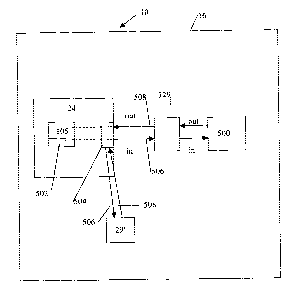
[0081] Referring to Figure 9, it is recognised that the object classes 29
COULD
communicate with external software 500, but the classes 29 does not HAVE to.
Object classes
29 could also contain logic themselves, for example. The following are
examples of each of the
above described scenarios.
[0082] The first scenario is where the object classes 29 implement logic
themselves (for
example the class logic would calculate the area described by the supplied
coordinates of the
message 506). In this example case, the object class 29 is instantiated as an
object 29'. The
Process method is called against the instantiated object 29'. The input string
506 is XML
containing four x,y co-ordinates. The instantiated Object 29' would perform
the math to
calculate the area embodied by the four co-ordinates. The instantiated Object
class object 29'
would return the area in the output string of the message 508. Further, it is
recognised that the
object class 29 (i.e. interface component) could be part of the operating
system 20 of the device
10.
[0083] The second scenario is where the object class 29 acts as a proxy to GPS
software 500
(this example retrieves the current GPS coordinates of the device 10). The
object class 29 is
instantiated through the corresponding interface 129. The Process method is
called against the
instantiated object and thus forwarded to the interface 129. The input string
506 could be a blank
string. The instantiated object would call, for example, the
GetCurrentCoordinates method
against the existing GPS software 500. The implementation of this interaction
between the
instantiated Object class interface 129 and the GPS software 500 is left to
the
designer/developer. The instantiated Object interface 129 would receive the
return value from
the GPS software 500, package the value into a meaningful (to the application
105) string
format and return it via the output string message 508.
Device 10
CA 02583840 2007-04-11
WO 2006/089387 PCT/CA2005/000229
22
[0084] Referring to FIG. 4, an example architecture of the mobile devices 10
is shown. The
mobile device 10 maybe any conventional mobile device 10, modified to function
in
conjunction with the network 8 environment. As such, the mobile device 10
includes a processor
12, in communication with a network interface 14, storage memory 16, and a
user interface 18
typically including a keypad and/or touch-screen. The computer processor 12
manipulates the
operation of the network interface 14, the user interface 18 and a display by
executing related
instructions, which are provided by an operating system 20 and the executing
application
application 105. The network interface 14 is coupled to the processor 12 and
enables the device
to transmit and receive data over the wireless network 36,38. The mobile
device 10 may be,
for example, be a Research in Motion (RIM) two-way paging device, a WinCE
based device, a
PalmOS device, a WAP enabled mobile telephone, or the like. The memory 16 of
device 10
stores a mobile operating system such as the PalmOS, or WinCE operating system
software 20.
Operating system software 20 typically includes graphical user interface 18
and network
interface 14 software having suitable application programmer interfaces
("API"s) for use by
other applications executing at device 10. The user interface 18 can include
one or more user
input devices such as but not limited to a keyboard, a keypad, a trackwheel, a
stylus, a mouse, a
microphone, and is coupled to a user output device such as a speaker (not
shown) and a screen
display. If the display is touch sensitive, then the display can also be used
as the user input
device as controlled by the processor 12. The user interface 18 is employed by
the user of the
device 10 to interact with the application 105 executing on the virtual
machine 24.
[0085] Memory 16 at device 10 further stores virtual machine software 24 for
enabling
device 10 to present an interface for the applications 105 provided, for
example, by the
middleware server 44. Specifically, the virtual machine software 24 interprets
the text
application definition file 28 defining: the user interface 18 controlling
application 105
functionality, and the display format (including display flow) at device 10
for a particular
application 105; the format of data to be exchanged over the wireless network
36,38 for the
application 105; and the format of data to be stored locally at device 10 for
the application 105.
The virtual machine software 24 uses the operating system 20 and associated
APIs to interact
with device 10, in accordance with the received application definition file
28. In this way, the
device 10 may present interfaces on the display for a variety of the
applications 105 enabled for
CA 02583840 2007-04-11
WO 2006/089387 PCT/CA2005/000229
23
interaction with selected data sources 70. Moreover, multiple wireless devices
10 each having
similar virtual machine software 24 may use a common data source 70 in
combination with the
application definition file 28, to present the corresponding user interface
screens and program
flow specifically adapted for the device 10. Further, it is recognized that
the device 10 can
include a computer readable storage medium 212 coupled to the processor 12 for
providing
instructions to the processor 12 and/or to load the applications 105 also
resident (for example) in
the memory module 16. The computer readable medium 212 can include hardware
and/or
software such as, by way of example only, magnetic disks, magnetic tape,
optically readable
medium such as CD/DVD ROMS, and memory cards. In each case, the computer
readable
medium 212 may take the form of a small disk, floppy diskette, cassette, hard
disk drive, solid
state memory card, or RAM provided in the memory module 16. It should be noted
that the
above listed example computer readable mediums 212 can be used either alone or
in
combination. Further, it is recognised that the definition files 28 could be
stored in the memory
16 or in a designated application definition file memory 26, as desired.
[0086] As such, and as will become apparent, the exemplary virtual machine
software 24 is
specifically adapted to work with the particular mobile device 10. Thus if
device 10 is a RIM
pager, virtual machine software 24 is a RIM virtual machine. Similarly, if
device 10 is a PalmOS
or WinCE device, virtual machine software 24 would be a PalmOS or a WinCE
virtual machine.
As further illustrated in FIG. 4, virtual machine software 24 is capable of
accessing local storage
26.
[0087] Other applications, libraries, and software, hereafter referred to as
local software 500
considered separate from the virtual machine 24 and the provisioned
applications 105, may also
be present within memory 16 or local storage 26. For example, device 10 may
store and execute
personal information management (PIM) software 500, including calendar and
contact
management applications 500. Similarly, device 10 could store and execute
software 500
allowing device 10 to perform a number of functions. Software 500 could, for
example such as
but not limited to, interact with the hardware of the device 10 to allow
device 10 to act as a
multimedia player; allowing device 10 to print; allowing device 10 to interact
with other
incorporated hardware not specifically illustrated, including but not limited
to a Bluetooth
CA 02583840 2007-04-11
WO 2006/089387 PCT/CA2005/000229
24
interface; a Global Positioning Satellite (GPS) Receiver; and the like. In the
depicted
embodiment, memory 16 stores interface components 29, for example in the form
of object
classes 29, that may be used to extend the functionality of virtual machine
software 24. This
extension of functionality can provide for internal communication (i.e. not
over the network 8)
between the virtual machine 24 and the software 500 (for example ultimately
between the
provisioned applications 105 and the software 500). As will become apparent,
these interface
components in the form of object classes 29 allow virtual machine software 24
to become
extensible so as to provide for the virtual machine 24 to call and/or
otherwise interact with the
local software 500. Object classes 29 may, for example, allow virtual machine
software 24 to
access additional hardware or software 500 local to device 10.
[0088] As detailed below, an exemplary application definition file 28 may be
formed using a
markup language, such as but not limited to XML. Defined XML entities of the
definition file
28 are understood by the virtual machine software 24. Defined XML entities are
detailed in
Appendix "A", hereto. The defined XML entities are interpreted by the virtual
machine software
24, and may be used as building blocks to provision the application 105 at
mobile device 10, so
as to generate and operate an executable version of the definition file 28 as
the application 105.
[0089] Specifically, as illustrated in FIG. 5, virtual machine software 24
includes a
conventional XML parser 61; an event handler 65; a screen generation engine
67; and object
classes 69 corresponding to XML entities supported by the virtual machine
software 24, and
possibly contained within an application defmition file 28. Supported XML
entities are detailed
in Appendix "A" hereto enclosed. A person of ordinary skill will readily
appreciate that those
XML entities identified in Appendix "A" are exemplary only, and may be
extended, or shortened
as desired.
[0090] XML parser 61 may be formed in accordance with the Document Object
Model
(DOM), for example, available at http://www.w3.org/DOM/, the contents of which
are hereby
incorporated by reference. Parser 61 enables virtual machine software 24 to
read the application
description file 28, once received by the device 10. Using the parser 61, the
virtual machine
software 24 may fomi a binary representation (i.e. the application 105), for
example, of the
CA 02583840 2007-04-11
WO 2006/089387 PCT/CA2005/000229
application definition file 28 for storage at the mobile device 10, thereby
eliminating the need to
parse text each time the corresponding application 105 is used. The parser 61
may convert each
XML tag contained in the application definition file 28, and its associated
data to tokens and/or
java byte code, for later processing during execution of the application 105
by the virtual
machine software 24 or other capabilities of the device 10 resources. As will
become apparent,
the conversion of the definition file 28 contents to the tokenized/byte code
representation may
avoid the need to repeatedly parse the text of an application definition file
28.
[0091] Screen generation engine 67 displays initial and subsequent screens at
the mobile
device, in accordance with an application description file 28, as detailed
below. The event
handler 65, of virtual machine sofl.ware 24 allows device 10 under control of
virtual machine
software 24 to react to certain external events. Example events include user
interaction with
presented screens or display elements, incoming messages received from a
wireless network, or
the like. Object classes 69 define objects that support the device 10 to
process each of the
supported XML entities at the mobile device 10. Each of object classes 69
includes attributes
used to store parameters defined by the XML file 28, and functions allowing
the contained XML
entities to be processed at the mobile device 10, as detailed in Appendix "A",
for each supported
XML entity. So, as should be apparent, supported XML entities are extensible.
Virtual machine
software 24 may be expanded to support XML entities not detailed in Appendix
"A".
Corresponding object classes could be added to virtual machine software 24, as
desired.
[00921 As detailed below, upon invocation of a particular application at
mobile device 10,
the virtual machine software 24 presents an initial screen on the user
interface 18 based on the
contents of the application definition file 28. Screen elements are created by
the screen
generation engine 67 by creating instances of corresponding object classes for
defined elements,
as contained within object classes 69. The object instances are created using
attributes contained
in the application definition file 28. Thereafter the event handler 65 of the
virtual machine
software 24 reacts to actions/events for the application 105. Again, the event
handler 65 consults
the contents of the application definition file 28 for the application 105 in
order to properly react
to events. Events may be reacted to by creating instances of associated
"action" objects, from
object classes 69 of virtual machine software 24. Further, it is recognised
that events/actions
CA 02583840 2007-04-11
WO 2006/089387 PCT/CA2005/000229
26
related to the XML definitions of screens, data, and messages can be
coordinated by workflow
elements 406 (see Figure 7) expressed in a scripting language, in addition to
or as an alternative
to the event handler 65. In this case, these workflow elements 406 could also
be part of, or
associated with, the definition file 28 for processing on the device 10 by a
script interpreter 66,
for example.
[0093] Similarly, object classes 69 of virtual machine software 24 further
include object
classes corresponding to data tables and network transactions defined in the
Table Definition and
Package Definition sections of Appendix "A". At run time, instances of object
classes
corresponding to these classes are created and populated with parameters
contained within
application definition file 28, as required.
[00941 Using this general description, persons of ordinary skill in the art
will be able to form
virtual machine software 24 for any particular device 10. Typically, virtual
machine software 24
may be formed using conventional object oriented programming techniques, and
existing device
libraries and APIs, as to function as detailed herein. As will be appreciated,
the particular format
of screen generation engine 67 and object classes 69 will vary depending on
the type of virtual
machine software 24, its operating system and API available at the device 10.
Once formed, a
machine executable version of virtual machine software 24 may be loaded and
stored at a mobile
device 10 (including downloading from the network 36,38, using conventional
techniques. It can
be embedded in ROM, loaded into RAM over the network, or from the computer
readable
medium 212. Although, in the preferred embodiment the virtual machine software
24 is formed
using object oriented structures, persons of ordinary skill will readily
appreciate that other
approaches could be used to form suitable virtual machine software 24. For
example, the object
classes forming part of the virtual machine 24 could be replaced by equivalent
functions, data
structures or subroutines formed using a conventional (i.e. non-object
oriented) programming
environment. Operation of virtual machine software 24 under control of an
application definition
file 28 containing various XML definitions exemplified in Appendix "A", is
further detailed
below.
CA 02583840 2007-04-11
WO 2006/089387 PCT/CA2005/000229
27
[0095] As so far described, in particular in section Operation of the
Application 105 set-up
and Device Communication given below, operation of virtual machine software 24
is limited by
those object classes 69 forming part of virtual machine software 24. However,
the interface
components 29 (e.g. the object classes 29), for example not forming part of
virtual machine
software 24, are further loaded within memory 16 of device 10. The interface
components 29
can be loaded in the memory 16 of the device 10 in response to known
capabilities of the
definition file 28. For example, if the definition file 28 contains
INTEGRATION tags (e.g. a
handler definition 502) configured for calling applications/software 500
external to the
application 105 (when provisioned in the virtual machine 24) then the
appropriate classes 29
could be uploaded to the device 10 (for example from the server 44) as an
accompaniment to the
XML descriptors of the definition file 28. These classes 29 would enable the
applications 105 to
take advantage of potential software 500 located locally in the memory 16 of
the device 10.
Conveniently, the object classes 29 may be created by a user (or
administrator) of device 10 and
therefore may not have to rely on access to the source code for virtual
machine software 24. It
should be recognised that communication interfaces 129 (e.g. optional
instantiated object
interfaces 129 of the classes 29) can provide for inter-application 105,500
communication on the
device 10 external to the network 8 environment. For example, the software 500
can be
applications not derived from definition files 28, however the definition file
28 contains the
handler definition 502 for calling the interface component 29 that coordinates
access to the
software 500 local to the device 10 through the interface 129.
[0096] The virtual machine software 24 includes a software code portion 504
(e.g.
communication service) that instantiates identified ones of object classes 29,
as called by the
handler definition 502 of the application 105, and the called class 29 then
executes methods
through the interface 129 for effecting communication between the application
105 and the
software 500 resident on the device 10. The software 500 is typically external
to the virtual
machine 24 and associated applications 105 provisioned from definition files
28. As such, the
virtual machine software 24 may be extended through the addition of additional
object classes
29, so as to allow the applications 105 and the virtual machine 24 itself to
communicate with the
software 500 through the interface 129.
CA 02583840 2007-04-11
WO 2006/089387 PCT/CA2005/000229
28
[0097] Although, in the preferred embodiment the virtual machine software 24
and object
classes 29 (for forming the communication interfaces 129) are formed using
object oriented
structures, persons of ordinary skill will readily appreciate that other
approaches could be used to
form suitable virtual machine software 24 and object classes 29. For example,
object classes 69
forming part of the virtual machine 24 could be replaced by equivalent
functions, data structures
or subroutines formed using a conventional (i.e. non-object oriented)
programming environment.
Object classes 29 could be similarly replaced with other software components
in the form of
libraries, sub-routines, programs, combinations thereof, or the like.
Inter-Application Interface Components 29
[0098] Referring to FIG 40, an INTEGRATION tag (i.e. handler definition 502)
of the
definition file 28 (incorporated in the application 105 as provisioned) takes
as arguments, the
name of an external one of classes 29 to be instantiated assigned to
CLSID=class_name, for
example, and the name of a local variable, returnvar, used by virtual machine
software 24 in
which results passed by the execution of the software 500 should be stored. As
well, the value
assigned to SAVE may be boolean and specify whether or not the data returned
by the
instantiated class 29 should be saved. The request message 506 from the
virtual machine 24 is
passed to the external software 500, which then returns a response message 508
to the
communication interface 129 which is then passed to the service 504 and
eventually, for example
associated with the handler definition 502 that originally called for the
software 500.
[0099] For example, class_name identifies one of classes 29 by name. The name
of the class
is assigned as described below. For example, the name of the local variable
corresponds to the
name of a variable associated with the handler definition 502 defined in
section 52 of the
application definition 28. Finally, the contents of the ACTION element (i.e.
rny input text) is
passed to the instantiated one of classes 29, as detailed below.
[00100] The exact way in which external accessible objects 129 (associated
with the classes
29) are formed and may be accessed by virtual machine software 24 will
typically depend on the
operating system software 20 of device 10 in association with which virtual
machine software 24
is executing. Virtual machine software 24 should, however, be able to identify
the external
CA 02583840 2007-04-11
WO 2006/089387 PCT/CA2005/000229
29
object class 29 and instantiate it. Optionally, virtual machine software 24
should be able to
verify that the external object class 29 has the interface 129 that conforms
to virtual machine
software 24. For example, for virtual machine software 24 written and
executing in a
WindowsCE environment, object classes 29 can be developed using the component
object model
(COM). The component object model (COM) is described at
http ://msdn.mi croso ft. com/library/default. asp?url=/library/en-
us/dnanchor/html/componentobjectmodelanchor.asp and D. Box, Essential COM,
(1997:
Addison-Wesley Professional) ISBN: 0201634465, the contents of which are
hereby
incorporated by reference. It is recognised that object classes 29 are
definable using COM, for
interpretation then by the service 504 and the external software 500 so as to
coordinate the
sending and receiving of the messages 506,508.
[00101] Briefly, for completeness, object classes 29 developed using COM are
registered with
the WindowsCE operating system 20. The operating system 20 maintains a list of
the COM
objects that have been created. Additionally, object classes 29 developed in
accordance with the
COM include one or more defined interfaces 129. Other operating systems 20
executing on
mobile devices 10 expose classes 29 that may be accessible by virtual machine
software 24 in
different ways. For example, RIM and PalmOS operating systems 20 expose
various PIM object
stores as Java Classes or C++ classes 29. A person of ordinary skill will
readily appreciate how
such classes 29 maybe used by virtual machine software 24 created for such an
operating system
20. It is recognised however that the definition file 28 should contain
handler definitions 502 so
as to help coordinate the workflow of the executing application 105 via the
service 504 and the
classes 29 when access to external software 500 is desired.
[00102] Object classes 29 written in accordance with the COM may register
their name with
the underlying operating system 20, and further include the interface 129. In
the preferred
embodiment, the interface 129 takes a name known by virtual machine software
24. For
example, the interface 129 of the class 29 may take the name
IAIRIXIntegrationPoint. In the
preferred embodiment the interface 129 defines a function with name HRESTJLT
that takes
parameter hWndParent, InputString, and OutputString. Variables InputString
(i.e. message 506),
CA 02583840 2007-04-11
WO 2006/089387 PCT/CA2005/000229
and OutputString (i.e. message 508) are populated by values passed to and from
the virtual
machine software 24 identifying attributes of the string SAVE_NAME.
[00103] The value of hWndParent identifies the main window generated by
virtual machine
software 24 as a result of the application definition file 28 instantiating
the object class 29. The
value may be used by the method of the instantiated class 29 to embed controls
on or as a parent
window to sub windows that the method creates as per application 105
execution. To summarize,
the interface 129 of the class 29 takes the form, such as but not limited to:
interface IAI RIXI nteg ration Point: IDispatch
{[id(1), helpstring("method Process")] HRESULT Process(VARIANT hWndParent,
BSTR InputString, BSTR* OutputString);}.
[00104] As will be appreciated, IDispatch signifies a standard COM interface;
id(1) signifies
that the method Process is listed as the first method exposed on the interface
129; and helpstring
may be used by a debugging tool, for example associated with the tool 116. The
method Process
(e.g. the software 500), in turn, performs the function to be implemented by
the external object
class 29 to perform the functionality of the software 500 desired by the
application 105, thus
extending the functions performed by virtual machine software 24 and related
applications 105.
For example, method "Process" could provide the interface 129 (optional) to
other object classes
29, or hardware at device 10. The method "Process" could for example gather a
signature, a
fingerprint, GPS co-ordinates, or virtually any other function that can be
performed by device 10.
Conveniently, the method "Process" may make use of the string data (of message
506) contained
as my input text and forming part of the XML element giving rise to the
instantiating of the class
29.
[00105] Upon completion of the method, results should be formatted by the
method and
placed in the variable OutputString (e.g. message 508), so the results may be
passed back to
virtual machine software 24 (and the requesting application 105) through the
interface 129
(optional) for fiirther processing. In the exemplary embodiment, the content
of OutputString is
XML formatted, so that it may be easily further processed by machine software
24 (or
alternatively middleware server 44).
CA 02583840 2007-04-11
WO 2006/089387 PCT/CA2005/000229
31
[00106] The value of Process returned by the method call may identify
successful execution
of the method. In response to an error code, virtual machine software 24 may
log an error and
report that error to the user of device 10 through a standard error message
dialog. As will be
apparent, the name of each class 29 is identified in the PROGID variable used
as each class 29 is
created and will be registered in accordance with COM, for example.
Operation of the Interface Components 29
[00107] Referring to Figure 35, in particular, if the NAME tag associated with
the action
identifies INTEGRATION tag (e.g. the handler definition 502), virtual machine
software 24
performs steps S l 100, as a result of executing the next action in step S
1012 of FIG 15. As
illustrated, virtual machine software 24 compares the value provided to the
CLSID variable to
the names of accessible classes 29 preferably not forming part of virtual
machine software 24.
[00108] In step S 1102, virtual machine software 24 queries the list of
available accessible
object classes. If objects classes 29 were created using COM, as detailed
above, this is
accomplished by querying the WindowsCE registry. If an object class 29
corresponding to the
class identified in the CLID (i.e. CLID=class name) variable is found as
determined in steps
S 1104, the class 29 is queried in step S 1106, to verify that the class 29
indeed extends virtual
machine software 24 to access the software 500 as determined by the class 29
associated with the
handler definition 502. Querying may be accomplished by querying the class 29
to determine if
it provides the interface 129 (optional) expected by virtual machine software
24. Specifically,
the class 29 may be queried to determine if it has the interface 129 having a
chosen name or type.
The interface 129 may be queried using the COM method Querylnterface(). In the
example the
object class 29 is queried to locate the interface 129 having the name
IAIRIXIntegrationPoint. If
the class 29 does not have the interface 129 (i.e. there is no software 500
corresponding to the
handler definition 502 as identified by the executing application 105, the
INTEGR.ATION action
is terminated by machine software 24 and an error message could optionally be
generated (i.e.
the user of the device 10 may be shown an error screen on the user interface
18 indicating that
the requested method (software 500) is not available).
CA 02583840 2007-04-11
WO 2006/089387 PCT/CA2005/000229
32
[00109] If the class 29 has the interface 129 (optional), the class 29 is
instantiated in step
S 1110 and a method having a chosen name (i.e. Process software 500) is
executed by virtual
machine software 24 in step S 1112. Parameters hWndParent and the input and
output strings
formed (i.e. my iriput text, returnvar passed to variable SAVENAME) part of
the tag and XML
element are passed to the method. As noted, the actual function of the method
is entirely
determined by the author of the class, and not the provider of virtual machine
software 24. Upon
completion of the executed method, the results of the method are passed back
to virtual machine
software 24, by assigning the result to the variable OutputString. If the SAVE
variable is set to
true, the results returned by the method can be stored in the variable
identified assigned to the
SAVENAME variable in step S 1114. If the identified class does not include the
expected
interface 129 as determined in step S 1108, the INTEGRATION action is
terminated. Again, an
error message could be generated as described above.
[00110] Conveniently, once data returned by the method call the data is stored
locally in the
variable defined in application definition 28 (according to the handler
definition 502) and then
becomes otherwise accessible by virtual machine software 24. It is recognised
that one or more
applications 105 could call a single object class 29 which optionally calls
the software 500
through interface 129. Otherwise, the called object class 29 could become the
instantiated object
29'. Of course, the contents of the variable may be acted upon as otherwise
dictated by the
application definition 28. Thus, contents of the variable may be presented as
part of the user
interface 18, or sent back to middleware server 44, for example as part of a
message defined in
portion 50 of the application definition 28 as identified by the <DATA> tag,
as detailed in
Appendix "A".
[00111] After execution of the method of the external class 29, additional
screens may be
created by invocation of the screen generation engine 67, as detailed in FIGS.
13 and 14. In this
manner the navigation through the screens of the application 105 is
accomplished according to
the definition embodied in the XML application definition file 28.
[00112] For the purposes of illustration, FIGS. 36A,B illustrates the
presentation of the user
interface 18 for a sample screen on a Windows CE Portable Digital Assistant
device 10, that has
CA 02583840 2007-04-11
WO 2006/089387 PCT/CA2005/000229
33
invoked an externally generated signature capture dialog (i.e. class 29), as a
result of an
externally instantiated object 129. The signature data is stored in a variable
LASTSIG, and sent
back to application server 44.
[00113] An example application definition file 92 (of the format of
application definition 28)
is illustrated in FIGS. 37, 38 and 39A-39B defines the class 29 entitled
SignatureCapture,
including a definition of local data in the form of a table titled LASTSIG
(FIG. 37), a format of
the user interface 18 having a single screen entitled MAIN (FIG. 39A-39B) and
the format of
network transactions (FIG. 38), corresponding to portions 52, 50 and 52,
respectively of the
application definition 28.
[00114] The screen has four single buttons identified by the 'BTN NAME'="
btnCapture",
BTN NAME'="btnView", 'BTN NAME'="btnSend", BTN NAME="btnClose". Upon
invocation of this class 29 at the local device 10, screen generation engine
67 (see figure 5) of
virtual machine software 24 at the device process the screen definition, as
detailed with reference
to FIGS. 13 and 14. That is, for each BTN tag, screen generation engine 67
creates a button
object instance, in accordance with steps S804-S812. The created buttons will
have captions
Capture New Signature, View Last Signature, Send to Server, and Close.
[00115] The resulting screen at the mobile device 10 is illustrated in FIG.
36A. Each of the
screen items is identified with reference to the XML segment within XML
definition file 92
giving rise to the screen element.
[00116] Call-backs associated with the presented buttons cause graphical user
interface 18 of
the class 29 and operating system software 20 at the mobile device 10 to
return control to the
event handler 65 of virtual machine software 24 at the device. Thus, as the
user interacts with the
class 29, the user may input data within the presented screen of the
application 105 using the
mobile device API.
[00117] Notably, if the button btnSend is pressed, a package of type SIG (as
defined in FIG.
38) is sent back to middleware server 44. However, if the buttons btnCapture
or btnView are
CA 02583840 2007-04-11
WO 2006/089387 PCT/CA2005/000229
34
captured steps S 1100 are performed to instantiate an external object class 29
named
AirixSignature.AirixSignatureCtrl, with arguments,
SAVENAME="SIGNATURE" SAVE="TRUE" for btnCapture, and
SAVENAME="" SAVE="FALSE">[SP.*.SIGNATURE]</ACTION>, for btnView.
[00118] An object class 29 named AirixSignature.AirixSignatureCtrl, of course
needs to exist,
be registered and expose the interface 129 of the forme
IAIRIXIntegrationPoint, as detailed
above. Its method Process, in turn, causes device 10 to capture a signature or
present the
signature. These functions may for example be provided using software written
for the
WindowsCE platform, in a manner appreciated by a person of ordinary skill. In
the case of the
btnCapture INTEGRATION action, the results of the method return a captured
signature, which
is stored in variable SIGNATURE by virtual machine software 24. In the case of
the btnView
the previously captured value stored in the variable SIGNATURE will be passed
to the instance
of the object class. The screen presented at device 10 in response to
performing the Process
method of the AirixSignature.AirixSignatureCtrl object class is displayed in
FIG. 36B.
[00119] As can be appreciated from the preceding description and example, use
of external
interface components in the form of object classes 29 provides for the virtual
machine software
24 to be expanded, almost arbitrarily. Conveniently, applications 105 may
still be defined using
an application definition file 28 in a manner relatively abstracted from the
underlying device 10.
Conveniently, as local software or hardware functions are added to devices 10,
virtual machine
software 24 and applications 105 defined in an application definition 28 may
take advantage of
the new functionality using external object classes 29 with associated handler
definitions 502 as
part of the definition file 28.
Application Design User Interface or Too1116
[00120] Referring to Figures 1 and 2, the definition files 28 representing the
applications 105
can be stored in the repository 114 as a series of packages that can be
created by the Studio
developer tool 116, which is employed by developers of the definition files 28
(e.g. XML
definitions for screens, messages, and data as well as action/event and
definitions/script). The
developer design tool 116 can be a RAD tool used to develop the definition
file 28 packages, in
CA 02583840 2007-04-11
WO 2006/089387 PCT/CA2005/000229
conjunction with simulation capabilities of the application 105 on the tool
116 using a simulated
version of the communication interface 914 (described above - see Figure 9)
that defines
communication between the message elements of the application(s) 105, the
middleware server
44, and various message and data structures of the data sources 70 via their
interface model 300.
The too1116 can provide support for a drag-and drop graphical approach for the
visual design of
the application 105, including simulation of application 105 operation as well
as simulation of
server 44 communication with the data sources 70.
[00121] For example, in a component based XML-Script application model, the
application
105 packages can be represented as metadata (XML) that can be generated
automatically by the
tool 116 through an automatic code generation process. The tool 116 can
provide for the
automatic generated code to. include application workflow descriptions using
an industry
standard scripting language (e.g. JavaScript) or other scripting/programming
languages known in
the art, as well as using XML tag implemented rules interpreted by the handler
65 (see Figure 5).
For example, the design editors 600, wizards 604, dialogs 605 and viewers 602
can be used to
access an interface component mode1301, which could contain all descriptions
of the interface
components 29 and related interfaces 129 that would/should be available on the
device 10 in
order to access related software 500 or to be used as instantiated objects
29'. it is recognised that
the mode1301 could be structured so as to make available stored classes 29
(e.g. interface
components) and software 500 on the tool 116, or the mode1301 could be used to
simulate the
interface components 29 though dialog boxes so as to allow the developer to
emulate the classes
29 and relate software 500 if not resident on the tool 116. For design time,
the developer would
use the model 301 to enter in the name of the object class 29 that the
application 105 will call
and then select. For runtime, the developer would use the model 310 to enter
an edit field input
that the developer wants the pplication 105 to call and then the application
would try to
instantiate the object class 29 specified. theis instantiation can be done
directly if the object class
29 is resident on the tool 116 or can be simulated through the dialog boxes.
The availability of
the definition file 28 packages of the repository 114 can be published via the
discovery service of
the server 110 in the registry 112. It is recognized that there can be more
than one repository 114
and associated registries 112 as utilized by the particular network 8
configuration of the
middleware server 44 and associated data sources 70.
CA 02583840 2007-04-11
WO 2006/089387 PCT/CA2005/000229
36
[00122] Referring to Figure 8, the tool 116 is operated on a computer 201 that
can be
connected to the network 8 environment via a network connection interface such
as a transceiver
200 coupled via connection 218 to a device infrastructure 204. The transceiver
200 can be used
to upload completed application programs 105 to the repository 114 (see Figure
1), as well as
access the registry 112 and selected data sources 70. Referring again to
Figure 8, the developer
design tool 116 also has a user interface 202, coupled to the device
infrastructure 204 by
connection 222, to interact with a user (not shown). The user interface 202
includes one or more
user input devices such as but not limited to a keyboard, a keypad, a
trackwheel, a stylus, a
mouse, a microphone, and is coupled to a user output device such as a speaker
(not shown) and a
screen display 206. If the display 206 is touch sensitive, then the display
206 can also be used as
the user input device as controlled by the device infrastructure 204. The user
interface 202 is
employed by the user of the tool 116 to coordinate the design of definition
files 28,58 in
conjunction with the application 105 simulation using the conununication
interfaces 300, 914
(see Figure 9) using a series of editors 600 and viewers 602 (see Figure 10)
and using a plurality
of wizards 604 to assist/drive in the workflow of the development process. The
communication
interfaces 300,914 are used during application 105 simulation to link data
structures of the
network communication messages 900 expected to and from the data sources 70.
It should be
noted that the tool 116 emulates the interface 914 (normally used by the
server 44) so as to
interact directly with the data sources 70 through the interface 300.
[00123] Referring again to Figure 8, operation of the tool computer 201 is
enabled by the
device infrastructure 204. The device infrastructure 204 includes a computer
processor 208 and
the associated memory module 210. The computer processor 208 manipulates the
operation of
the network interface 200, the user interface 202 and the display 206 of the
tool 116 by executing
related instructions, which are provided by an operating system and definition
file 28 and/or
communication interface model 300 design editors 600, wizards 604, dialogs 605
and viewers
602 resident in the memory module 210. Further, it is recognized that the
device infrastructure
204 can include a computer readable storage medium 212 coupled to the
processor 208 for
providing instructions to the processor 208 and/or to load/design/simulate the
applications 105
also resident (for example) in the memory module 210. The computer readable
medium 212 can
CA 02583840 2007-04-11
WO 2006/089387 PCT/CA2005/000229
37
include hardware and/or software such as, by way of example only, magnetic
disks, magnetic
tape, optically readable medium such as CD/DVD ROMS, and memory cards. In each
case, the
computer readable medium 212 may take the form of a small disk, floppy
diskette, cassette, hard
disk drive, solid state memory card, or RAM provided in the memory module 210.
It should be
noted that the above listed example computer readable mediums 212 can be used
either alone or
in combination.
[00124] Referring again to Figure 2, the design tool 116 is operated on the
computer 201 as a
development environment for developing the applications 105 and/or application
105 simulation
through interaction with the data sources 70 via the communication interface
mode1300. The
development methodology of the tool 116 can be based on a visual "drag and
drop" system of
building the application visual, data, messaging behaviour, and runtime
navigation mode1610.
The tool 116 can be structured as a set of plug-ins to a generic integrated
design environment
(IDE) framework, such as but not limited to the Eclipse framework, or the tool
116 can be
configured as a complete design framework without using plug-in architecture.
For exemplary
purposes only, the tool 116 will now be described as a plug-in design
environment using the
Eclipse framework.
[00125] Referring to Figure 10, Eclipse makes provisions for a basic, generic
tool 116
environment that can be extended to provide custom editors, wizards, project
management and a
host of other functionality. The Eclipse Platform is designed for building
integrated
development environments (IDEs) that can be used to create applications as
diverse as web sites,
embedded Java TM programs, C++ programs, and Enterprise JavaBeans TM. The
navigator
view 230 shows files in a user's (e.g. developer) workspace; a text editor
section 232 shows the
content of a file being worked on by the user of the tool 116 to develop the
application 105 in
conjunction with the interface mode1300 in question; the tasks view section
234 shows a list of
to-dos for the user of the tool 116; and the outline viewer section 236 shows
for example a
content outline of the application 105 being designed/edited/simulated, and/or
may augment
other views by providing information about the currently selected object such
as properties of the
object selected in another view. It is recognised that the tool 116 aids the
developer in creating
and modifying the coded definition content of the definition files 28 in view
of the application
CA 02583840 2007-04-11
WO 2006/089387 PCT/CA2005/000229
38
105 simulation via a simulator module 629, for example in a structured
definition language (e.g.
in XML). Further, the tool 116 also aids the developer in creating, modifying,
simulating, and
validating the interdependencies of the definition content between the
application message/data
and/or screen/data relationships included in the definition files 28 and the
communication
interface model 300. It is also recognised that presentation on the display of
wizard 604 and
dialog 605 content for use by the developer (during use of the editors 600 and
viewers 602) can
be positioned in one of the sections 230,232,234,236 and/or in a dedicated
wizard section (not
shown), as desired.
[00126] The Eclipse Platform is built on a mechanism for discovering,
integrating, and
running modules called plug-ins (i.e. editors 600 and viewers 602). When the
Eclipse Platform
is launched via the UI 202 of the computer 201, the user is presented with an
integrated
development environment (IDE) on the display 206 composed of the set of
available plug-ins,
such as editors 600 and viewers 602. The various plug-ins to the Eclipse
Platform operate on
regular files in the user's workspace indicated on the display 206. The
workspace consists of one
or more top-level projects, where each project maps to a corresponding user-
specified directory
in the file system, as stored in the memory 210 (and/or accessible on the
network 10), which is
navigated using the navigator 230. The Eclipse Platform UI paradigm is based
on editors, views,
and perspectives. From the user's standpoint, a workbench display 206 consists
visually of views
602 and editors 600. Perspectives manifest themselves in the selection and
arrangements of
editors 600 and views 602 visible on the display 206. Editors 600 allow the
user to open, edit,
and save objects. The editors 600 follow an open-save-close lifecycle much
like file system
based tools. When active, a selected editor 600 can contribute actions to a
workbench menu and
tool bar. Views 602 provide information about some object that the user is
working with in the
workbench. A viewer 602 may assist the editor 600 by providing information
about the
document being edited. For example, viewers 602 can have a simpler lifecycle
than editors 600,
whereby modifications made in using a viewer 602 (such as changing a property
value) are
generally saved immediately, and the changes are reflected immediately in
other related parts of
the display 206. It is also recognised that a workbench window of the display
206 can have
several separate perspectives, only one of which is visible at any given
moment. Each
CA 02583840 2007-04-11
WO 2006/089387 PCT/CA2005/000229
39
perspective has its own viewers 602 and editors 600 that are arranged (tiled,
stacked, or
detached) for presentation on the display 206.
Designer Too1116 Architecture
[00127] Figure 10 illustrates the overall designer tool 116 structure for
designing applications
105 and/or simulating the applications 105 using the associated interface 300
(accessible over the
network 8 environment) and emulating interface 914. The designer tool 116 user
interface (UI
202 and display 206 - see Figure 8) is primarily a user facing module 601
(i.e. composer
modules) collection of graphical and text editors 600, viewers 602, dialogs
605 and wizards 604.
The large majority of external interactions are accomplished through one or
more of these editors
600, with the developer/user, using a system of drag and drop editing and
wizard driven
elaboration. The secondary and non-user facing system interface is that of the
"Backend",
whereby the tool 116 connects to and digests data source 70 services such as
Web Services and
SQL Databases through simulation of the application 105 via the interfaces
300,914. As
described above, the tool 116 can be built on the Eclipse platform, whereby
the user interface
system components can be such as but not limited to components of editors 600,
viewers 602,
dialogs (not shown) and wizards 604, which are plug-in modules 601 that extend
Eclipse classes
and utilize the Eclipse framework, for example. As shown, the tool 116
communicates with
backend data sources 70 and may communicate with the UDDI repositories 114 and
registries
112.
UI Layer 606
(00128] The tool 116 has a UI Layer 606 composed mainly of the editors 600 and
viewers
602, which are assisted through the workflow wizards 605. The layer 606 has
access to an
extensive widget set and graphics library known as the Standard Widget Toolkit
(SWT), for
Eclipse. The UI layer 606 modules 601 can also make use of a higher-level
toolkit called TFace
that contains standard viewer classes such as lists, trees and tables and an
action framework used
to add commands to menus and toolbars. The modules 601 can be used to insert
the handler
definitions 502 in the definition file 28, in accordance with the object
classes 29 of the interface
model 301. It is recognised that knowledge of the associated interfaces 129 of
the classes 29 can
be used by the developer in developing the definition file 28 so as to take
advantage of known
CA 02583840 2007-04-11
WO 2006/089387 PCT/CA2005/000229
software 500 available on the device 10. As well, the developer can also
update the contents of
the interface mode1301(for the latest in available software 500) so as to help
in developing
upgrades to existing definition files as per existing design time models 608.
The tool 116 can
also use a Graphical Editing Framework (GEF) to implement diagramming editors.
The UI layer
606 modules 601 can follow the Model-View-Controller design pattern where each
module 601
is both a view and a controller. Data models 608,610 represents the persistent
state of the
application 105 and are implemented in the data model layer 612 the tool 116
architecture. The
separation of the layers 606, 612 keeps presentation specific information in
the various views
and provides for multiple UI modules 601 (e.g. editors 600 and viewers 602) to
respond to data
mode1608,610 changes. Operation by the developer of the editors 600 and
viewers 602 on the
display 202 (see Figure 2) can be assisted by the wizards 604 for guiding the
development of the
application 105 and/or simulation through the interfaces 300,914.
[00129] Referring to Figure 6, the UI Layer 606 is comprised of the set of
editors 600, viewers
602, wizards 604 and dialogs 605. The UI Layer 606 uses the Model-View-
Controller (MVC)
pattern where each UI module 601 is both a View and a Controller. UI Layer
modules 601
interact with data models 608,610 with some related control logic as defined
by the MVC
pattem. The editors 600 are modules 601 that do not commit model 608,610
changes until the
user of the tool 116 chooses to "Save" them. Viewers 602 are modules 601 that
commit their
changes to the model 608,612 immediately when the user makes them. Wizards 604
are modules
601 that are step-driven by a series of one or more dialogs 605, wherein each
dialog 605 gathers
certain information from the user of the tool 116 via the user interface 202
(see Figure 8). No
changes are applied to the design time model 608 using the wizards 604 until
the user of the tool
116 selects a confirmation button like a "Finish". It is recognised in the
example plug-in design
tool 116 environment, modules 601 can extend two types of interfaces: Eclipse
extension points
and extension point interfaces. Extension points declare a unique package or
plug-in already
defined in the system as the entry point for functional extension, e.g. an
editor 600, wizard 604
or project. Extension point interfaces allow the tool 116 to define its own
plugin interfaces, e.g.
for skins 618 and backend 616 connectors, as further described below.
Data Models 608, 610, 301
CA 02583840 2007-04-11
WO 2006/089387 PCT/CA2005/000229
41
[001301 The tool 116 data models 608,610,301 are based, by example, on the
Eclipse
Modeling Framework (EMF). The framework provides model 608, 610,310 change
notification,
persistence support and an efficient reflective API for manipulating EMF
objects generically.
The code generation facility is used to generate the mode1608, 610,301
implementation and
create adapters to connect a model layer 612 with the user interface modules
601 of the UI layer
606.
[00131] Referring again to Figure 6, modules 601 (primarily Editors 600 and
Viewers 602) in
the tool 116 are observers of the data models 608,610,301 and are used to
interact or otherwise
test/simulate and modify the data models 608,610,301 of the application (e.g.
components 400,
402, 404, 406 - see Figure 4) in question. When the data model 608,610,301
changes, the
models 608,610,301 are notified and respond by updating the presentation of
the application
105. The tool 116 uses the Eclipse Modeling Framework (EMF), for example, to
connect the
Eclipse UI framework to the tool 116 data mode1608,610,301, whereby the
modules 601 can use
the standard Eclipse interfaces to provide the information to display and edit
an object on the
display 206 (see Figure 2). In general, the EMF framework implements these
standard interfaces
and adapt calls to these interfaces by calling on generated adapters that know
how to access the
data mode1608,610,301 and example communication methods 908,910,912 (see
Figure 9) of the
interface 914 residing in memory 210. The design time Data Model 608 is used
to represent the
current version of the application 105 (e.g. an application module) in
development and is
accessed by the users employing the modules 601 to interact with the
associated data of the
mode1608. Modules 601 can also trigger validation actions on the Design Time
Data Model
608. Modules 601 can also cause some or all of the application 105 to be
generated from the
Design Time Data Mode1608 resident in memory 210. In general, the Design Time
Data Model
608 accepts a set of commands via the UI 202 (see Figure 2) that affect the
state of the model
608, and in response may generate a set of events. Each module 601 (editor 600
and viewer 602)
described includes the set of commands and the events that affect the module
601 and data model
608 pairing.
[00132] Referring to Figure 10, the Runtime Data Mode1610 represents the state
of an
emulated/simulated application 105 under development by the tool 116, in
conjuction with the
CA 02583840 2007-04-11
WO 2006/089387 PCT/CA2005/000229
42
simulator module 629, using as a basis the contents of the design time data
model 608. The
runtime data mode1610 stores values for the following major items, such as but
not limited to:
Data Components 400 (see Figure 7); Global Variables; Message Components 404;
Resources;
Screen Components 402 and Styles as well as definition sections 48,50,52 where
desired. The
Runtime Data Model 610 collaborates with the Design Time Data Model 608 and a
Testing/Preview viewer of the simulator module 629 during emulation/simulation
of application
105 for testing and preview purposes (for example). The viewer also
collaborates with the skin
manager 616 for emulating/simulating the runtime data mode1610 for a specified
device 10 type.
The Runtime Data Mode1610 also notifies, through a bridge 613, the viewer as
well as any other
modules 601of the UI layer 606 associated with changes made to the model 610.
For example,
an API call can be used as a notifier for the associated modules 601 when the
state of the model
610 has changed. The Design Time Data Mode1608 represents the state of an
application 105
development project and interacts with the modules 601 of the UI layer 606 by
notifying
modules 601 when the state of the mode1608 has changed as well as saving and
loading objects
from storage 210. The model's 608 primary responsibility is to define the
applications 105
including such as but not limited to the following items: Data Component 400
Definitions;
Global Variable Definitions; Message Component 404 Defiuiitions; Resource
304,306
Definitions; Screen Component 402 Definitions; Scripts 406; Style Definitions
and definition
sections 48,50,52 where appropriate. The Design Time Data Model 608 responds
to commands
of each editor 600, viewer 602. The Design Time Data Mode1608 also fires
events to modules
601 in response to changes in the model 608, as well as
collaborating/communicating with the
other modules 601 (module 601-module 601 interaction) by notifying respective
modules 601
when the data model 608 has changed. The data model 608 depends on an
interface in order to
serialize model 608 content retrieval and storage to and from the memory 210.
[00133] The interface mode1301 contents are used to guide the developer in
inserting handler
definitions 502 in the definition file 28. the handler definitions 502 are
formatted, for example as
given above by example, so as to be recognizable and processed by the service
504 of the virtual
machine 24. It is recognised that the developer can use the interface model
301 as a library of
available handler definitions 502 and their related interfaces 129 and
software 500.
CA 02583840 2007-04-11
WO 2006/089387 PCT/CA2005/000229
43
[00134] The above describes the mechanism used by the tool 116 editors 600 and
viewers 602
to interact with the models 608,610 and methods 908,910,912 of the interfaces
300,914. The
EMF.Edit framework is an optional framework provided by the Eclipse framework.
The tool
116 can use the EMF.Edit framework and generated code (for example) as a
bridge or coupling
613 between the Eclipse UI framework and the tool models 608,610,300.
Following the Model-
View-Controller pattern, the editors 600 and viewers 602 do not know about the
models 608,610
directly but rely on interfaces to provide the information needed to display
and edit.
Service La, ey r 614
[00135] Referring again to Figure 6, a service layer 614 provides facilities
for the UI layer 606
such as validation 620, localization 624, generation 622, build 626, simulator
module 629 and
deployment 628, further described below. The tool 116 can make use of the
Eclipse extension
point mechanism to load additional plug-ins for two types of services: backend
connectors 616
and device skin managers 618 with associated presentation environments 630.
[001361 The backend connector 616 defines an Eclipse extension point to
provide for the tool
116 to communicate with or otherwise obtain information about different
backend data sources
70, in order to obtain the message format (e.g. as provided by WSDL
definitions) of the selected
data source 70 and/or to communicate with the respective data source 70 of the
application 105
(under development) during simulation via the simulation module 629. The
backend connector
616 can be used as an interface to connect to and to investigate backend data
source 70 services
such as Web Services and SQL Databases via the emulated interface 914 through
the
communication interface 300 (of the data sources 70). The backend connector
616 facilitates
simulating the suitable application message and data set 900 to permit
communication with these
services from the application 105 when simulated running on the device 10.
Further, it is
recognised that the backend connector 616 and/or the simulator module 629 can
be used to
emulate the communication interface 914, also used by the server 44 when the
application 105 is
eventually deployed to the network 8 environment. The backend connector 616
can support the
access to multiple different types of data sources 70 through the interfaces
300914, such as but
not limited to exposing respective direct communication interfaces through a
communication
connector based architecture. At runtime the tool 116 reads the plug-in
registry to add
CA 02583840 2007-04-11
WO 2006/089387 PCT/CA2005/000229
44
contributed backend extensions to the set of backend connectors 616, such as
but not limited to
connectors for Web Services.
[00137] The Backend Connector 616 can be responsible for such as but not
limited to:
connecting to a selected one (or more) of the backend data sources 70 (e.g.
Web Service,
Database) through the interfaces 300,914; providing an interface for accessing
the description of
the backend data source 70 (e.g. messages, operations, and data types); and/or
providing for the
identification of Notification services (those which push notifications over
the network 8 to the
device 10 - see Figure 1). The Backend Connector 616 can provide an interface
to the
communicate with the backend data source 70 (e.g. a web service, SQL Database
or other) and
can provide a level of abstraction between implementation specific details of
the backend
messaging and generic messaging processing of the messages 900 of the data
source business
logic 902 situated in the data source 70 behind the interface model 300.
[00138] The device skin manager 618 defines an Eclipse extension point, for
example, to
allow the tool 116 to emulate different devices 10 (see Figure 1), such tliat
the look and feel of
different target devices 10 (of the application 105) can be specified. At
runtime the tool 116
reads the plug-in registry to add contributed skin extensions or presentation
environments 630 to
the set of device environments 630 coordinated by the manager 618, such as but
not limited to
environments 630 for a generic BlackBerry TM or other device 10. The Skin
Manager 618 is
used by the Testing/Preview viewer 806 to load visual elements of the data
mode1608,610 that
look appropriate for the device 10 that is being emulated, i.e. elements that
are compatible with
the specified environment 630. Different skins or presentation
environments/formats 630 are
"pluggable" into the manager 618 of the tool 116, meaning that third parties
can implement their
own presentation enviromnents 630 by creating new unique Skinlds (an Eclipse
extension point),
for example, and implementing an appropriate interface to create instances of
the screen
elements supported by the runtime environment RE of the emulated device 10. In
order to load a
new presentation environment 630, the Testing/Preview viewer 806 first asks
the Manager 618
for an instance of the specified environment 630. The Manager 618 then
instantiates the
environment 630 and the Testing/Preview viewer 806 uses the specified
environment 630 to
construct the screen elements according to the screen components of the model
608,610. For
CA 02583840 2007-04-11
WO 2006/089387 PCT/CA2005/000229
example, the presentation environments 630 (e.g. SkinPlugins) are identified
to the SkinManager
618 through a custom Eclipse extension point using the Eclipse framework.
[00139] Further, the tool 116 can have a software module 621 for providing
software 500 for
interaction with the embedded handler definitions 502 of the simulated
application 105. The
software 500 can be instantiated in the memory 210 of the computer 201 of the
tool 116 and/or
the developer can have dialog boxes 605, for example, to simulate the presence
of the software
500 during simulation of the application 105. For example, the dialog boxes
605 would visualize
on the user interface 202 (see FIG 8) the input and required output data of
the messages 506,508
(see Figure 40) as the simulated software 500 is in communication with the
simulated application
105.
[00140] The model validation 620 of the service layer 614 provides facilities
for the UI layer
606 such as validating the design time data mode1608 in conjunction with the
interface model
300. The ModelValidator 620 is used to check that the representation of
application 105
messages is in line with the backend data source 70 presentation of messaging
operations via the
interface model 300. The Model Validator 620 can be responsible to validate
the model 608
representation (i.e. content of definition files 28) of the application 105 to
be generated, for
example such as but not limited to elements of: workflow sanity of the
workflow elements;
consistency of parameters and field level mappings of the components data,
message and screen
elements; screen control mappings and screen refresh messages of the screen
elements; message
and/or data duplications inter and intra screen, message, data, and workflow
elements. Another
function of the validation 620 can be to validate the interface model's 300
representation of
backend data source 70 messaging relationships as implemented by the emulated
application
105. In order to achieve its responsibilities, the validator 620 can
collaborate with the Design
Time Data Mode1608, the interfaces 300,914, an application generator 622, the
simulator
module 629 and the backend connector 616. The Model Validator 620 utilizes as
part of the
validation task the Design Time Data Mode1608 (for application 105 validation)
and the
message structures 900 (for interfaces 300,914 compatibility validation), as
well as the backend
connector 616, which supports the interface to the backend data sources 70
through the defined
communication interfaces 300,914.
CA 02583840 2007-04-11
WO 2006/089387 PCT/CA2005/000229
46
[00141] Refemng again to Figure 10, the localization Service 624 has
responsibilities such as
but not limited to: supporting a build time localization of user visible
strings; supporting
additional localization settings (e.g. default time & date display format,
default number display
format, display currency format, etc); and creating the resource bundle files
(and resources) that
can be used during preparation of the deployable application 105 (e.g. an
application jar file) by
a BuildService 626. For example, the localization service 624 can be
implemented as a resource
module for collecting resources that are resident in the design time data
model 608 for inclusion
in the deployable definition file 28. The JAR file can be a file that contains
the class, image, and
sound files for the application gathered into a single file and compressed for
efficient
downloading to the device 10. The Localization Service 624 is used by the
application
Generator 622 to produce the language specific resource bundles, for example.
The BuildService
626 implements preparation of the resource bundles and packaging the resource
bundles with the
deployable application definition file 28. The Localization Service 624
interacts (provides an
interface) with the tool editors 600 and viewers 602 for setting or otherwise
manipulating
language strings and locale settings of the application 105.
[00142] Referring to Figure 10, the Generator 622 can be responsible for, such
as but not
limited to: generation of the application XML from the components definition
sections 48,50,52
(and components 400,402,404 as desired); optimizing field ordering of the
component/section
descriptors; and generation of dependencies and script transformation (for
action/event
operation) as desired for storage in the memory 210. The Generator 622
collaborates with the
Design Time Data Model 608 to obtain the content of the developed definition
sections 48,50,52
(and components 400,402,404 as desired) comprising the application 105, as
well as cooperating
with the selected communication interface model 300 to generate the messages
900 for use by
the middleware server 44. The Generator 622 utilizes the Model Validator 620
to check that both
the application definitions (of the file 28) are correct. The Generator 620
then produces the
XML code of the file 28, with inclusions and/or augmentations of the
script/handler of the
workflow elements. The Generator 622 uses the Localization Service 624 to
produce language
resource bundles, through for example a Resource Bundles interface (not
shown). The Generator
622 generation process can be kicked off through a Generate interface accessed
by the developer
CA 02583840 2007-04-11
WO 2006/089387 PCT/CA2005/000229
47
using the UI 202 of the tool 116 (i.e. by user input events such as mouse
clicks and/or key
presses). It is recognised that the generator 622 can be configured as a
collection of modules,
such as but not limited to a code module for generating the XML (which may
include associated
script). It is recognised that the generator module 622 could also generate
the required classes 29
as per the embedded handler definitions 502 of the file 28. These classes 29
could be associated
with the definition file 28, for example published or otherwise made available
to the users of the
device 10 and the services of the data source 70 related to the definition
file 28.
[00143] The deployment service 628 is used to deploy the appropriate
application definitions
file 28 with respect to the repository 114 and registry 112 and/or middleware
server 44. The
Build Service 626 provides a mechanism for building the deployable form of the
definitions file
28. The Build Service 626 produces via a build engine the deployable
application file 28. These
files 28 are made available to the deployment service 628 via an output
interface of the tool 116.
The security service 632, has the ability to sign the application file 28 to
prevent tampering with
their contents, and to provide the identity of the originator. There can be
two example options for
signing, either making use of DSA with SHA1 digest, or RSA with MD5, as is
know in the art.
For example, the security service 632 can handle certificates that are used
for application file 28
signing. The security service 632 can have the ability to request, store and
use a public/private
key pair to help ensure the validity of both the originator and content of the
application files 28
as deployed. It is recognised that the service 628 could also deploy the
interface model 301 to
the repository 114 and registry 112 and/or middleware server 44.
Simulator Module 629 and Interfaces 300,914
[00144] The simulator module 629 uses the simulated interface 914 along with
the interface
300 to provide for direct communication of the simulated application 105 with
the data source
70, via the back end connector module 616, preferably over the network 8
environment. The
interface 300 and simulated interface 914 can be defined as a framework for
organizing and
representing messaging information used by the middleware server 44 and/or
tool 116 to
facilitate communication between the application 105 and the data sources 70.
In the context of
the developer tool 116, the interface 300 and simulated interface 914 provide
for direct
communication between the tool 116 and the respective data source 70 during
simulation of the
CA 02583840 2007-04-11
WO 2006/089387 PCT/CA2005/000229
48
application 105 under development. It is recognised that the interfaces
300,914 can be used for
application 105 simulation while the definitions file 28 is in development, or
can be used once
the definitions file 28 development is complete.
[00145] The tool 116 is equipped with the simulator module 629 that simulates
device
applications 105 on their respective intended wireless device 10 types. The
simulator module
629 in conjunction with the backend connector 616 for connecting over the
network 8
environment to the respective data source 70 (via the interfaces 300,914),
provides the
opportunity to test the application 105 (as represented by the description
file 28 under
development) without using the actual intended wireless device 10. The
simulator module 629
can use a version of the virtual machine software 24 to simulate operation of
the application 105
as well as to provide run-time debugging information, which can be used to
minimize errors in
the application's 105 operation on the actual device 10 real-time.
[00146] Referring to Figure 9, the simulator module 629 provides for mimicking
the XML
message transactions 900 normally occurring between the middleware server 44
and the data
source 70 once the application 105 is deployed to the device 10. It should be
recognised that the
middleware server 44 does not have to be present to simulate the application
105 using the tool
116, rather the application 105 connection point (i.e. network address) is
temporarily directed to
the network address of the tool 116 (represented as network link 904) when
simulating the
interface 914. Before the tested application 105 is eventually deployed to the
network 8
environment and installed on the device 10, the connection point associated
with the definition
file 28 (of the application 105) is reset to the address of the interface 914
of the middleware
server 44 (represented as network link 906), which is in communication with
the data source 70.
Accordingly, rather than directing the enterprise application of the data
source 70 to the
middleware Server 44, the IP address of the computer 201 hosting the simulator
module 629 is
used for messaging 900 via the link 904. Further, by example only, SOAP files
of the interface
914 can be used by the simulator module 629 to emulate the basic
communications of the
interface 914 normally operated by the middleware Server 44. However, it
should be recognised
that in both cases (pre- and post-application 105 deployment) that the
interfaces 300,914 (and
associated communication protocols/methods 908,910,912 - see Figure 12) are
used both during
CA 02583840 2007-04-11
WO 2006/089387 PCT/CA2005/000229
49
application 105 development and after deployment. It is recognised that the
data source 70 is
configured for use of the communication methods 908,910,912 in conjunction
with the interface
mode1300.
[00147] Using the simulator module 629, the device application 105 under
development can
through a first scenario communicate directly with the enterprise application
of the data source
70, through the emulated server interface 914, as the application 105 would
normally operate
when deployed on the wireless device 10. In this case the actual middleware
server 44 used to
assist in communication between the data source 70 (through the interface 914)
and the device
is not used. It is recognised that the tool 116 could also communicate in a
second scenario
through the actual middleware server 44 during simulation of the application
105 by the tool 116,
if desired. In the second scenario, the connection for the point for the
simulated application 105
would be the middleware server 44, represented by the network link 903 as
understood by a
person skilled in the art. In this second scenario, the tool 116 would be
emulating network
communication of the device 10 when in actual operation of the application
105, while the actual
middleware server 44 of the network 8 environment would be responsible for
communication
through the interfaces 300,914 with the data source 70. In either scenario,
use of the interfaces
300,914 is employed, either by the tool 116 directly or by the middleware
server 44 directly.
[00148] The simulator module 629 in conjunction with the skin manager 618 and
selected
environments 630 can provide different simulator environments 630 for each of
the wireless
device 10 types supported by the data source 70. Much like the devices 10
themselves, the
different simulator environments 630 have varying navigation characteristics,
which provide for
respective imitation of actions of the wireless user for a respective device
10 type. Listed below
is an example of an RIM simulator environment 630 for representing the screen
display of the
application 105 when in communication with the data source 70, based on the
type of wireless
device 10 selected and the specified device skin simulator environment 630.
Referring to Figure
11, two viewing tabs 1100,1101 are available from the main simulator interface
1102 of the user
interface 202 (see Figure 8). Display tab selection 1100, for example the
default simulator
view, provides for control and navigation of the device application 105 under
simulation. The
data tab selection I 101 displays the data that is currently held in the
application's 105 local data
CA 02583840 2007-04-11
WO 2006/089387 PCT/CA2005/000229
tables (intended for storage in the memory 16 of the device 10 - see Figure
4), in a graphical
database form for example. The Data view can be updated continuously as the
simulator module
629 runs the device application 105.
1001491 Referring again to Figure 11, the Simulator module 629 can be set to a
number of
different display options using a Project Options window 1104. One significant
display setting
involves the debugging windows 1104, which display various details regarding
the operation of
the device application 105 during the simulation. Any combination of the five
(for example)
debugging windows 1104 can be displayed in the user interface 202 (see Figure
8), depending on
developer preferences. For example, choosing not to view any of the windows
1104 may be
appropriate during sales presentations and demonstrations, as it gives the
simulator module's 629
display characteristics most similar to the actual wireless device 10. The
following windows
1104 can be displayed as a part of the simulator module operation, such as but
not limited to:
Incoming XML 1106 - displays the XML Transactions received by the device
application
105;
Outgoing XML 1108 - displays the XML Transactions that are constructed and
sent from
the device application 105;
Query Execution 1110- displays any queries, in the form of SQL statements (for
example) that have been executed on the device 10 data tables;
Event Execution 1112 - lists the events and actions that are executed during
the
application's 105 operation; and
Scratchpad Values 1114 - displays the current status of the device scratchpad,
identifying any values currently retained by the application 105.
Selecting an item listed in any of the five debugging windows 1104 can display
any additional
information to the above, if available.
Operation of the Application 105 Simulation
[00150] A method for simulating the application 105 for subsequent deployment
on the
mobile device 10, the mobile device 10 configured for using the deployed
application 105 to
communicate over the network 8 with the data source 70 through the transaction
server 44, the
method comprising the steps of, such as but not limited to: executing the
simulated application
CA 02583840 2007-04-11
WO 2006/089387 PCT/CA2005/000229
51
105 to generate at least one message configured for receipt by the simulated
communication
interface 914 of the transaction server 44; simulating the server
communication interface 914 for
receiving the message and for transmitting the asynchronous message 900
intended for
transmission to the data source 70 via the interface 300; establishing a
connection to the network
8 by the tool 116 and transmitting the asynchronous message 900 over the
network 8 to the data
source 70; wherein the simulated server communication interface 914 is used to
monitor the
status (i.e. return value if any) of the transmitted asynchronous message 900.
Application 105 and Associated Definition File 28
[00151] As noted, the text definition files 28 defining application
definitions and data may be
formatted in XML. For example XML version 1.0, detailed in the XML version 1.0
specification
second edition, dated Oct. 6, 2000 and available at the internet address
"http://www.w3.org/TR/2000/REC-xml-2000- 1006", the contents of which are
hereby
incorporated herein by reference, may be used. However, as will be appreciated
by those of
ordinary skill in the art, the functionality of storing XML definition files
28 is not dependent on
the use of any given programming language or database system. Each application
definition file
28 is formatted according to defined rules and uses pre-determined XML markup
tags, known by
both virtual machine software 24, and complementary middleware server software
68. Tags
define XML entities used as building blocks to present the application 105 at
the mobile device
10. Knowledge of these rules, and an understanding of how each tag and section
of text should
be interpreted, allows virtual machine software 24 to process the XML
application definitions of
the file 28 and thereafter execute the application 105, as described below.
Virtual machine
software 24 effectively acts as an interpreter for a given application
definition file 28.
[00152] FIG. 6 illustrates an example format for the XML application
definition file 28. As
illustrated, the example application definition file 28 for a given device 10
and data source 70
service includes three components: a user interface definition section 48,
specific to the user
interface 18 for the device 10, and defining the format of screen or screens
for the application
105 and how the user interacts with them; a network transactions definition
section 50 defining
the format of data to be exchanged with the data source 70; and a local data
definition section 52
defining the format of data to be stored locally on the mobile device 10 by
the application 105.
CA 02583840 2007-04-11
WO 2006/089387 PCT/CA2005/000229
52
[00153] Defined XML markup tags correspond to XML entities supported at the
device 10,
and are used to create the application definition file 28 using the tool 116
(see Figure 1). The
defined tags may broadly be classified into three categories, corresponding to
the three sections
48, 50 and 52 of the application definition file 28. Example XML tags and
their corresponding
significance are detailed in Appendix "A". As noted above, virtual machine
software 24 at the
mobile device 10 includes object classes corresponding to each of the XML
tags. At run time,
instances of the objects are created as required to execute the definition
file 28 as the application
105.
[00154] Broadly, the following example XML tags may be used to define the user
interface
definition 48, such as but not limited to:
SCREEN--this defines a screen. A SCREEN tag pair contains the definitions of
the user
interface elements (buttons, radio buttons, and the like) and the events
associated with the screen
and its elements;
BUTTON--this tag defines a button and its associated attributes;
LIST--this tag defines a list box;
CHOICEBOX--this tag defines a choice item, that allows selection of a value
from
predefined list;
MENU--the application developer using the tool 116 will use this tag to define
a menu
for a given screen;
EDITBOX--this tag defines an edit box;
TEXT ITEM--this tag describes a text label that is displayed;
CHECKBOX--this tag describes a checkbox;
HELP--this tag can define a help topic that is used by another element on the
screen;
IMAGE--this tag describes an image that appears on those displays that support
images;
ICON--this tag describes an icon;
EVENT--this defines an event to be processed by the virtual machine software
24. Events
can be defined against the application as a whole, individual screens or
individual items on a
given screen. Sample events would be receipt of data over the wireless
interface, or a edit of text
in an edit box; and
CA 02583840 2007-04-11
WO 2006/089387 PCT/CA2005/000229
53
ACTION--this describes a particular action that might be associated with an
event
handler. Sample actions would be navigating to a new window or displaying a
message box
[00155] The second category of example XML tags describes the network
transaction section
50 of application definition file 28. These may include the following example
X1VIL tags such as
but not limited to;
TABLEUPDATE--using this tag, the application developer using the tool 116 can
define
an update that is performed to a table in the device's 10 local storage.
Attributes allow the update
to be performed against multiple rows in a given table at once; and
PACKAGEFIELD--this tag is used to define a field in a data package that passes
over the
wireless network 36,38;
[00156] The third category of XML tags used to describe the application 105
are those used to
define a logical database that may be stored at the mobile device 10. The tags
available that may
be used in this section are such as but not limited to:
TABLE--this tag, and its attributes, define a table. Contained within a pair
of TABLE
tags are definitions of the fields contained in that table. The attributes of
a table control such
standard relational database functions as the primary key for the table; and
FIELD--this tag describes a field and its attributes. Attributes of a field
are those found in a
standard relational database system, such as the data type, whether the field
relates to one in a
different table, the need to index the field, and so on.
[00157] As well as the above described example XML tags for the definition
file 28, the
virtual machine software 24 may, from time to time, need to perform certain
administrative
functions on behalf of the user of the device 10. In order to do this, one of
object classes 69 can
have its own repertoire of tags to communicate its needs to the middleware
server 44. Such tags
differ from the previous three groupings in that they do not form part of the
application definition
file, but are solely used for administrative communications between the
virtual machine software
24 and the middleware server 44. Data packages using these tags are composed
and sent due to
user interactions with the virtual machine's configuration screens. The tags
used for this can
include such as but not limited to:
CA 02583840 2007-04-11
WO 2006/089387 PCT/CA2005/000229
54
REG--this allows the application 105 to register and deregister the user for
use with the
middleware server 44;
FINDAPPS--by using this operation, users can interrogate the server 44 for the
list of
applications that are available to them;
APP REG--using this operation, the end-user can register (or deregister) for
the data
source 70 service and have the application 105 interface downloaded
automatically to their
device 10, via the definition file 28, (or remove the interface description
from the device's 10
local storage); and
SETACTIVE--If the user's preferred device 10 is malfunctioning, or out of
power or
coverage, they will need a mechanism to tell the Server 44 to attempt delivery
to a different
device 10. The SETACTIVE command allows the user to set the device 10 that
they are
currently using as their active one.
[00158] One specific type of ACTION understood by virtual machine software 24
is referred
to as a "INTEGRATION" action. This action is identified as an ACTION having an
ACTION
TYPE="INTEGRATION" tag Specifically, the format of the TYPE tag identifying
the
INTEGRATION action takes the form
<ACTION TYPE ="INTEGRATION" CLSID = "class name"
SAVENAME="returnvar" SAVE="true/false"t> my input text<IACTION>,
as further described above with respect to the section Inter-Application
Interface Components
29.
[00159] A further embodiment of the application 105 can, for example, the
applications 105
can be packaged definition files 28 for transmission to, and subsequent
execution on, the device
having application elements or artifacts such as but not limited to XML
definitions,
communication interface 300,914 definitions, application resources, and
optionally resource
bundle(s) for localization support. XML file definitions of the file 28 can be
XML coding of
application data, messages, screens components (optionally workflow
components), part of the
raw uncompiled application 105. It is recognised that XML syntax is used only
as an example of
any structured definition language applicable to coding of the applications
105. The XML
CA 02583840 2007-04-11
WO 2006/089387 PCT/CA2005/000229
definitions may be produced either by the tool 116 generation phase, described
above, or may be
hand-coded by the developer as desired. The application XML definitions can be
generically
named and added to the top level (for example) of a jar file.
[00160] The resources are one or more resources (images, soundbytes, media,
etc...) that are
packaged with the definition file 28 as static dependencies. For example,
resources can be
located relative to a resources folder (not shown) such that a particular
resource may contain its
own relative path to the main folder (e.g. resources/icon.gif,
resources/screens/clipart_1.0/happyface.gif, and
resources/soundbytes/midi/inthemood.midi).
The resource bundles can contain localization information for each language
supported by the
application 105. These bundles can be locatred in a locale folder, for
example, and can be named
according to the language supported (e.g. locale/lang_en.properties and
locale/lang_fr.properties).
[00161] For example, the runtime environment machine 24 of the device 10 can
be the client-
resident container within which the applications 105 are executed on the
device 10. The
container can manage the application 1051ifecycle on the device 10
(provisioning, execution,
deletion, etc.) and is responsible for translating the metadata (XML) of the
definition file 28,
representing the application 105 (in the case of raw XML definitions), into an
efficient
executable form on the device 10. The application 105 metadata is the
executable form of the
XML definitions and can be created and maintained by the runtime environment
machine 24.
The machine 24 can also provide a set of common services to the application
105, as well as
providing support for optional JavaScript or other scripting languages. These
services include
support for such as but not limited to UI control, data persistence and
asynchronous client-server
messaging. It is recognised that these services could also be incorporated as
part of the
application 105, if desired.
[00162] Referring to Figure 7, as an example only, the definitions file 28 can
be component
architecture based software applications 105 which can have artifacts written,
for example, in
eXtensible Markup Language (XML) and a subset of ECMAScript. XML and
ECMAScript are
standards-based languages, which allow software developers to develop the
component
CA 02583840 2007-04-11
WO 2006/089387 PCT/CA2005/000229
56
applications 105 in a portable and platform-independent way. A block diagram
of the
component application 105, as the definitions file 28, comprises data
components 400,
presentation components 402 and message components 404, which are coordinated
by workflow
components 406 through interaction with the client runtime environment machine
24 of the
device 10 (see Figure 1) once provisioned thereon. The structured definition
language (e.g.
XML) can be used to construct the components 400, 402, 404 as a series of
metadata records,
which consist of a number of pre-defined elements representing specific
attributes of a resource
such that each element can have one or more values. Each metadata schema
typically has
defined characteristics such as but not limited to; a limited number of
elements, a name of each
element, and a meaning for each element. Example metadata schemas include such
as but not
limited to Dublin Core (DC), Anglo-American Cataloging Rules (AACR2),
Government
Information Locator Service (GILS), Encoded Archives Description (EAD), IMS
Global
Learning Consortium (IMS), and Australian Government Locator Service (AGLS).
Encoding
syntax allows the metadata of the components 400, 402, 404 to be processed by
the runtime
environment RE (see Figure 1), and encoding schemes include schemes such as
but not limited
to XML, HTML, XHTML, XSML, RDF, Machine Readable Cataloging (MARC), and
Multipurpose Internet Mail Extensions (MIME). The client runtime environment
machine 24 of
the device 10 can operate on the metadata descriptors of the components 400,
402, 404 to
provision an executable version of the application 105, as described above by
example with
relation to the virtual machine 24 of Figure 5.
[00163] Referring again to Figure 7, the data components 400 define data
entities, which are
used by the application 105. Data components 400 define what information is
required to
describe the data entities, and in what format the information is expressed.
For example, the data
component 400 may define information such as but not limited to an order which
is comprised of
a unique identifier for the order which is formatted as a number, a list of
items which are
formatted as strings, the time the order was created which has a date-time
format, the status of
the order which is formatted as a string, and a user who placed the order
which is formatted
according to the definition of another one of the data components 400.
CA 02583840 2007-04-11
WO 2006/089387 PCT/CA2005/000229
57
[00164] Referring again to Figure 7, the message components 404 define the
format of
messages used by the component application 105 to communicate with external
systems such as
the web service of the data source 70. For example, one of the message
components 404 may
describe information such as but not limited to a message for placing an
order, which includes
the unique identifier for the order, the status of the order, and notes
associated with the order. It
is recognised that data definition content of the components can be shared for
data 400 and
message 404 components that are linked or otherwise contain similar data
definitions. The
message component 404 allows the message content to be evaluated to determine
whether
mandatory fields have been supplied in the message and to be sent to the data
source 70 via the
middleware server 44.
[00165] Referring again to Figure 7, the presentation components 402 define
the appearance
and behavior of the component application 105 as it displayed by the user
interface 18 of the
devices 10. The presentation components 402 can specify GUI screens and
controls, and actions
to be executed when the user interacts with the component application 105
using the user
interface. For example, the presentation components 402 may define screens,
labels, edit boxes,
buttons and menus, and actions to be taken when the user types in an edit box
or pushes a button.
It is recognised that data definition content of the components can be shared
for data 400 and
presentation 402 components that are linked or otherwise contain similar data
definitions.
[00166] Referring to Figures 1 and 7, it is recognized that in the above
described client
component application 105 definitions hosting model, the presentation
components 402 may
vary depending on the client platform and environment of the device 10. For
example, in some
cases Web Service consumers do not require a visual presentation. The
application definition of
the components 400, 402, 404, 406 of the component application 105 can be
hosted in the Web
Service repository 114 as a package bundle of platform-neutral data 400,
message 404, workflow
406 component descriptors with a set of platform-specific presentation
component 402
descriptors for various predefined client runtimes machines 24. When the
discovery or
deployment request message for the application 105 is issued, the client type
would be specified
as a part of this request message. In order not to duplicate data, message,
and workflow
metadata while packaging component application 105 for different client
platforms of the
CA 02583840 2007-04-11
WO 2006/089387 PCT/CA2005/000229
58
communication devices 10, application definition files 28 can be hosted as a
bundle of platform-
neutral component definitions linked with different sets of presentation
components 402. For
those Web Service consumers, the client application 105 would contain selected
presentation
components 402 linked with the data 400 and message 404 components through the
workflow
components 406.
[00167] Referring again to Figure 7, the workflow components 406 of the
component
application 105 define processing that occurs when an action is to be
performed, such as an
action specified by a presentation component 402 as described above, or an
action to be
performed when messages arrive from the middleware server 44 (see Figure 1).
Presentation,
workflow and message processing are defined by the workflow components 406.
The workflow
components 406 can be written as a series of instructions in a programming
language (e.g. object
oriented programming language) and/or a scripting language, such as but not
limited to
ECMAScript, and can be (for example) compiled into native code and executed by
the runtime
environment 206, as described above. An example of the workflow components 406
may be to
assign values to data, manipulate screens, or send/receive messages. As with
presentation
components, multiple workflow definitions can be created to support
capabilities and features
that vary among devices 10. ECMA (European Computer Manufacturers Association)
Script is a
standard script language, wherein scripts can be referred to as a sequence of
instructions that is
interpreted or carried out by another program rather than by the computer
processor. Some other
example of script languages are Perl, Rexx, VBScript, JavaScript, and Tcl/Tk.
The scripting
languages, in general, are instructional languages that are used to
manipulate, customize, and
automate the facilities of an existing system, such as the devices 10.
[00168] Referring to Figure 7, the application 105 is structured, for example,
using component
architecture such that wheri the device 10 (see Figure 1) receives a response
message from the
middleware server 44 containing message data, the appropriate workflow
component 406
interprets the data content of the message according to the appropriate
message component 404
definitions. The workflow component 406 then processes the data content and
inserts the data
into the corresponding data component 400 for subsequent storage in the device
10. Further, if
needed, the workflow component 406 also inserts the data into the appropriate
presentation
CA 02583840 2007-04-11
WO 2006/089387 PCT/CA2005/000229
59
component 402 for subsequent display on the display of the device 10. A
further example of the
component architecture of the applications 105 is for data input by a user of
the device 10, such
as pushing a button or selecting a menu item. The relevant workflow component
406 interprets
the input data according to the appropriate presentation component 404 and
creates data entities,
which are defined by the appropriate data components 400. The workflow
component 406 then
populates the data components 400 with the input data provided by the user for
subsequent
storage in the device 10. Further, the workflow component 406 also inserts the
input data into
the appropriate message component 404 for subsequent sending of the input data
as data entities
to the data source 70, web service for example, as defined by the message
component 404.
[00169] An example component application 105 represented in XML and mEScript
could be
as follows, including data components 400 as "wcData" and message components
404 content as
"wcMsg",:
<wcData name="User">
<dfield name="name" type="String" key="1"/>
<dfield name="passwordHash" type="String"/>
<dfield name="street" type="String"/>
<dfield name="city" type="String"/>
<dfield name="postal" type="String"/>
<dfield name="phone" type="String"/>
</wcData>
<wcData name="OrderStatus">
<dfield name="confNumber" type="Number" key=" 1 "/>
<dfield name="status" type="String"/>
<dfield name="datetime" type="Date"/>
</wcData>
<wcData name="Order">
<dfield name="orderld" type="Number" key="1"/>
<dfield name="special" type="String"/>
<dfield name="user" cmp="true" cmpName="User"/>
<dfield name="datetime" type="Date"/>
<dfield name="orderStatus" cmp="true" cmpName="OrderStatus"/>
</wcData>
<wcData name="Special">
<dfield name="desc" key="1" type="String"/>
<dfield name="price" type="Number"/>
</wcData>
<wcMsg name="inAddSpecial" mapping="Special">
</wcMsg>
<wcMsg name="inRemoveSpecial" pblock="mhRemoveSpecial">
CA 02583840 2007-04-11
WO 2006/089387 PCT/CA2005/000229
<mfield name="desc" mapping=-"Special.desc"/>
</wcMsg>
<wcMsg name="inOrderStatus">
<mfield name="orderld" mapping=-"Order.orderld"/>
<mfield name="status" mapping="Order.orderStatus"/>
</wcMsg>
<wcMsg name="inUserlnfo" mapping="User">
<IwcMsg>
<wcMsg name="outOrder">
<mfield name="special" mapping="Order.special"/>
<mfield name="user" mapping="Order.user"/>
<mfield name="datetime" mapping="Order.datetime"/>
</wcMsg>
[00170] As given above, the XML wcData element content defines the example
data
component 400 content, which is comprised of a group of named, typed fields.
The wcMsg
element content defines the example message component 404, which similarly
defines a group of
named, typed fields.
Example Interface 914
[00171] Referring to Figure 9, the application server 70 may either be
configured to poll the
transaction server 44 for messages queued to an application on server 70 or
the transaction server
44 may push messages on a queue toward the application on the server 70. To
support the latter
operation, the server 44 or the tool 116 uses the exposed listening interface
300 in combination
with the interface 914. The interface 300 may be one of a COM, DCOM, SOAP,
.NET, or
.NETRemoting interface 300 which has been configured for listening for
asynchronous
messages.
[00172] In the following, the transaction server 44 is sometimes referred to
as an ATS.
Further, the application server 70 is sometimes referred to as an enterprise
server (since the
application server and the mobiles 10 which utilise applications 105 on the
data base 70 are often
part of the same enterprise). Additionally, the defined XML entities of the
definition file 28
supported by the VM 24 of the mobiles 10 may be referred to hereinafter as
ARML entities.
CA 02583840 2007-04-11
WO 2006/089387 PCT/CA2005/000229
61
[00173] The requirement is quite simply to PUSH the message 900 from the ATS
to the
Enterprise server. The following three components are used by the PUSH
mechanism of the
interface 914:
1) The ARML application defines a delivery type (e.g. push via COM, SOAP,
.NET, etc),
and the associated details;
2) The ATS implements the logic to push the message 900; and
3) The ATS implements a mechanism by which message 900 delivery is guaranteed,
even
when the data base 70 is temporarily offline during an attempt to push the
message 900.
Therefore, the ATS can implement some form of automatic retry logic.
[00174] In addition, the ATS ensures that all messages 900 delivered to
enterprise
applications of the data source 70 are delivered in the order in which they
were received.
Incoming messages 900 from mobiles 10 are handled by the ATS in the same
manner
irrespective of whether the ATS forwards these messages 900 on to the
enterprise server 70 as a
result of polling or by pushing. In this regard, the method 908,910,912 for
example (which may
be named the AIRIXEnterpriseRouter.SendAppZicationMessage) is called, which
results in the
data source 70-bound message 900 being placed in the queue of queues 690 (FIG.
2) which is
specific for the data source 70 (TBLAPPLICATIONQUEUE) to which the message 900
is
bound through the interface 300. If the enterprise server 70 polls, then this
is all the ATS does -
it leaves the message 900 in the Queue 690 for the enterprise server 70 to
pick up via the PULL
delivery type.
[00175] If the ATS is aware that a given application on the enterprise server
70 is configured
to accept PUSHES of a particular delivery type (e.g., SOAP delivery type),
then in addition to
the above logic, a _Send method in an AIRIXEnterpriseRouter object will now
call the a new
AIRIXEnterpriseWakeup component (coupled to the interface 914) asynchronously.
This new
component (described in greater detail hereinafter) will be responsible for
pushing all queued
messages 900 for the data source 70 out. The AIRIXEnterpriseWakeup component
will in turn
call one of several new push specific components, namely such as but not
limited to:
0 AIRIXEnterprisePushCOM;
CA 02583840 2007-04-11
WO 2006/089387 PCT/CA2005/000229
62
= AIRIXEnterprisePushSOAP; and
= AIRIXEnterprisePushRemoting.
[00176] These new components may be part of an application namespace called
Nextair.AIRIX. Server.Enterprise.Push.
(00177] Without any special handling, this solution could easily result in
duplicate messages
900 being pushed to the enterprise application of the data source 70. To help
combat this
problem, the AIRIXEnterpriseWakeup components first attempt to obtain a lock
for the
application it wants to push to through the interface 300. If this lock is
successfully obtained, the
AIRIXEnterpriseWakeup component of the interface 914 proceeds to push all
queued messages
900 for the enterprise application of the data source 70, and release the lock
of the interface 300
when finished. Otherwise, if the AIRIXEnterpriseWakeup component cannot obtain
the lock, it
will do nothing (immediately exit, without error). Finally, where the
Transaction Server 44 is
scaled sideways (i.e. works in a clustered environinent), the enterprise
application of the data
source 70 locks are held in a central location - otherwise it could be
possible for different
machines (referencing the same backend 70 database) to attempt pushing the
same messages 900
at once - resulting in duplicate (and possibly out of order) messages 900. The
details for the
proposed locking mechanism are discussed hereinafter.
[00178] In the case where an enterprise application of the data source 70 is
currently offline
when the ATS attempts to push to it, the pushing attempt will terminate and
the remaining
messages 900 will be left in the application queue 690. Again, without special
handling, an
attempt to push these remaining messages 900 to the enterprise application of
the data source 70
would not occur until the next message 900 was received from the mobile 10 for
that enterprise
application of the data source 70 (which, for low volume installations, could
be quite a long
time). In order to help prevent this from happening, an automatic retry
mechanism of the
interface 914 may be implemented whereby the ATS will automatically check for
old queued
messages 900 every X minutes (on a timer). If old queued messages are found,
the
AIRIXEnterpriseWakeup object of the interface 914 will be fired for the
appropriate application.
CA 02583840 2007-04-11
WO 2006/089387 PCT/CA2005/000229
63
[00179] Upon successful insertion of the application-bound message into the
ATS Application
Queue, the AIRIXEnterpriseRouter of the interface 914 can:
~ Lookup the delivery type and push details for the appropriate enterprise
application of the
data source 70; and
~ If the enterprise application of the data source 70 is a PUSH delivery type
(anything other
than PULL), call the AIRIXEnterpriseWakeup component of the interface 914,
asynchronously, triggering a push of the new message 900 (and any other queued
messages for the enterprise application of the data source 70).
[00180] FIG. 21 illustrates pseudo-code for implementing the asynchronous call
to the
AIRIXEnterpriseWakeup component from the AIRIXEnterpriseRouter _Send method
908,910,912. The AIRIXEnterpriseRouter can also contain a new method called
Retry. This
method may be called by a Retry Service (further detailed hereinafter) to
automatically retry
sending/pushing any expired queued messages 900. The method will simply
retrieve a list of
push-enabled applications that have outstanding queued messages 900, and call
the Wakeup
method against the AIRIXEnterpriseWakeup component for each enterprise
application of the
data source 70. A simple implementation (without error handling) is set out in
FIG. 22.
[00181] Ideally, an error trying to create the AIRIXEnterpriseWakeup component
in the
_Send method should not result in the transaction being rolled back. Instead,
an error can be
logged, and the retry left up to the built-in automatic retry mechanism of the
ATS. The
AIRIXEnterpriseWakeup NET queued component is responsible for initiating
pushing to
enterprise applications of the data source 70. This component ideally can be
called
asynchronously by other components to ensure that lengthy enterprise pushes do
not hinder other
code from executing.This class will belong to the
Nextair.AIRIX.Server.Enterprise.Router
nainespace.
[00182] AIRIXEnterpriseWakeup can be a.NET queued component containing a
single
exposed method called Wakeup. This method will be called primarily by the
AIRIXEnterpriseRouter component of the interface 914 when the data source 70-
bound message
900 comes in from the mobile 10. The automatic push retry mechanism of the ATS
will also call
CA 02583840 2007-04-11
WO 2006/089387 PCT/CA2005/000229
64
this component on a regular configurable interval. A call to the Wakeup method
of this
component signifies a request to push all currently queued messages 900 for
the enterprise
application of the data source 70. Because the AIRIXEnterpriseWakeup component
can be a
COM+ (pooled) component, it is possible that (without some special handling)
two or more
AIRIXEnterpriseWakeup components could be attempting to push messages 900 to a
single
enterprise application of the data source 70 at the same time. To help resolve
this issue, the
Wakeup method can try to obtain a "push lock" via the interface 300 for the
enterprise
application of the data source 70 it needs to push to, before actually doing
the work. If the lock
can be obtained, this component will proceed to attempt to push all queued
messages 900 for the
enterprise application of the data source 70. Otherwise, if the lock cannot be
obtained, the
Wakeup method will do nothing (because another Wakeup component may currently
own the
lock).
[00183] In order to help support sideways scaling of the Transaction Server 44
(for high
volume, hosting type installation scenarios), the ATS can be capable of
holding these "locks" in
a central location - one that all AIRIXEnterpriseWakeup components, on all
participating
Transaction Servers 44 can use to obtain and release locks of the interface
300. At the same
time, since it is much more likely that the Transaction Server 44 will not be
scaled sideways,
ideally there chould also be a faster, and less dependent locking mechanism
that does not need to
communicate across application (or machine) boundaries. The locking
implementation for both
of these scenarios is explained below.
[00184] An AIRIXLockManager Class (which is a.NET class) can contain the logic
required
for obtaining and releasing locks for multiple resources, where a resource is
a push-enabled
application activated on an ATS. Since pushing to one enterprise application
of the data source
70 should not be dependent on pushing to other enterprise applications of the
data source 70, this
class will be able to keep track of and manage independent locks for multiple
enterprise
applications of the data source 70. The basic implementation for this class is
shown in FIG. 23.
[00185] Both the AIRIXEnterpriseWakeup component and a Remote Locking Service
(detailed hereafter) of the interface 914 can use the above lock class to hand
out application
CA 02583840 2007-04-11
WO 2006/089387 PCT/CA2005/000229
locks. Since the AIIZIXEnterpriseWakeup component and the Transaction Server
can be hosted
in different application spaces, they may not share the static members of the
lock class. The
reason for having this lock object located in both places is so that the
Transaction Server 44 can
use a central locking location (i.e. located in the Remote Locking Service) in
the rare case where
the ATS needs to be scaled to multiple machines. The Remote Locking Service
can expose the
lock object via a.NET Remoting interface 300, which all cooperating ATS
machines will need
to query for obtaining and releasing locks. However, since NET Remoting can
require extra
overhead (i.e. TCP/IP conununication over a specific port), it is also
preferable to have the
ability to obtain locks without having this Remoting overhead. Therefore, the
lock object located
in the AIRIXEnterpriseWakeup component can be used when the ATS is installed
solely on a
single server machine.
[00186] The COM+ construct string for the AIRIXEnterpriseWakeup component will
contain
an XML configuration string indicating:
= Whether the ATS should run in clustered mode (off by default).
= If specified to run in clustered mode (above), the computer name (or IP
address) and port
for the Remote Locking Service interface 300 to be used as the central lock
provider
(normally one of the machines in the cluster).
[00187] When called, the Wakeup method in the AHRIXEnterpriseWakeup component
will
perform the following:
Attempt to obtain a lock for the specified enterprise application of the data
source 70
=. If the lock can be obtained (i.e. is not already obtained by another
caller), then:
o Create an instance of the appropriate AIRIXEnterprisePushBase descendent
component (depending on the passed in delivery type).
o Call the Push method on the created push component, passing it the
application ID,
delivery type, and delivery details for the application to push messages 900
out to.
CA 02583840 2007-04-11
WO 2006/089387 PCT/CA2005/000229
66
[00188] A basic implementation of the AIRIXEnterpriseWakeup component is shown
in
FIGS. 24A and 24B This component could have attributes such that object
pooling is enabled,
object construction is enabled, and it has a transactional type of
"Required".Any single push
message 900 failure during the execution of the Wakeup method chould result in
the termination
of the pushing attempt, followed by a release of the enterprise application of
the data source 70
lock. of the interface 300. This will provide that messages 900 are sent
sequentially (in the order
they were received). The push attempt will be retried either the next time an
application-bound
message is received from a mobile 10 for that enterprise application of the
data source 70, or
when the automatic push retry is executed (whichever comes first). In this
regard, it will be
recalled that a push message failure is judged to have occurred when the
enterprise server 70
returns a message indicating the failure or when, during a push attempt, a
communications
protocol layer times out.
[00189] An interface called IAIRIXEnterprisePush of the interface 914 may
serve as a base
type for all descendent classes that need to implement PUSH functionality.
This class may
belong to a namespace identified as the Nextair.AIRIX ServeY.Enterprise.Push.
The actual use of
this class is documented hereinafter, however, the C# source code for this
interface definition is
shown in FIG. 25.
[00190] An enterprise push abstract base class can be created, which will
parent all push
implementation classes. This abstract class can provide common functionality
to all of its child
classes. The class can belong to a namespace identified as
Nextair.AIRIX.Server.Enterprise.Push
namespace. The AIRIXEnterprisePushBase class can inherit NextairDatabase,
which provides
general database access and component services routines. This abstract base
class can provide
basic functionality required from all push components. The class will
initially provide a single
public method (called Pus1a). The Push method will provide a base
implementation of the
message 900 push. It can call the abstract createPush Client method to do the
actual work of
connecting to and/or obtaining a reference to an IAIRTXEnterprisePush object
that can be used to
push a message 900 out to the interface 300. Since this method is abstract,
all children classes
will implement it. The template of FIGS. 26A and 26B suggests a basic
implementation for this
class.
CA 02583840 2007-04-11
WO 2006/089387 PCT/CA2005/000229
67
[00191] Since the sending of an actual message 900 to the enterprise
application of the data
source 70 is a non-transactional request, the moveQueueToLog method should be
called before
attempting to push a message 900 out (as can be seen in the sample
implementation above). If
the push fails, the transaction will be aborted, causing moveQueueToLog to be
rolled back. Note
that if this were done in the reverse order, the push could succeed, then
MoveQueueToLog could
fail - in which case the push would not be able to be rolled back (because it
is non-
transactional), and a duplicate message would eventually be delivered to the
enterprise
application of the data source 70. In the event that MoveQueueToLog fails, the
transaction
should be aborted and the caller (child class) should not attempt to push the
message.
[00192] The following discusses suitable implementations for the delivery
types COM,
DCOM, SOAP, Net, and NetRemoting of the interface 300.
COM and DCOM
[001931 To configure the Transaction Server 44 so as to be able to push data
source 70-bound
messages 900 to enterprise server applications via COM, a COM push can be
created in a
namespace identified as Nextair.AIRLY Server.Erzterprise.7'ush. The COM
interface 300 can be
exposed by enterprise applications of the data sources 70 wishing to receive
inbound data via
COM interface 300. This interface 300 may be deployed with the Transaction
Server44 (in a
"lib" directory), and can be a simple COM type library file (.tlb) that can be
imported by
Enterprise Application developers and implemented.
[00194] The COM interface 300 in conjunction ith the interface 914 will
declare the following
methods:
= AIRIXReceiveData 908 - Called by the ATS when a message is to be pushed to
an
enterprise application.
= AIRIXDeliveryError 910 - Called by the ATS when an error occurs trying to
deliver a
message to a mobile.
= AIRIXDeliveryNotify 912 - Called by the ATS when a message is successfully
delivered
to a mobile.
CA 02583840 2007-04-11
WO 2006/089387 PCT/CA2005/000229
68
[00195] The MIDL skeleton code of FIG. 27 declares the COM interface 300
enterprise
applications of the data source 70 can to implement to receive COM PUSH
messages 900 from
the interface 914 of the ATS.
[00196] In order for the ATS to push the message 900 to the COM based
enterprise
applications of the data source 70, the COM component developed for the
enterprise application
of the data source 70 should meet the following:
1) Implement the IA.IRIXEnterprisePush COM interface 300 exposed by the
Transaction
Server 44 (in the ATS "lib" directory) according to the interface 914.
2) Register the COM component on the Transaction Server 44 machine. Note that
communication over DCOM is also possible provided the appropriate DCOM
settings are
applied to the component on the ATS machine.
3) Specify the ProgID (Class and CoClass) of the COM component (for example,
"DispatchForce.AIRIXReceive") in the delivery details of the enterprise
application of
the data source 70, which is provisioned via the Transaction Server 44
Console.
[00197] A.NET Serviced Component named AIRIXEnterprisePushCOM inherits from
AIRIXEnterprisePushBase and handles the actual pushing of data (via COM) to
enterprise
application of the data source 70. The implementation of the
AIRIXEnterprisePushBase
createPushClient method for this class can create an instance of the COM
component that is
specified in the delivery details of the associated enterprise application of
the data source 70.
The "delivery details" string for COM PUSH enabled enterprise applications of
the data source
70 is simply the ProgID (Class.CoClass) of the COM component to push to. The
pseudo-code of
FIG. 28. shows a basic implementation of the createPushClient method for the
AIRIXEnterprisePushCOM component (without error handling).
SOAP
[00198] To allow pushing via SOAP, a push component of the interfaces 300, 914
capable of
executing method calls against a Web Service via SOAP over HTTP is used. The
location
CA 02583840 2007-04-11
WO 2006/089387 PCT/CA2005/000229
69
(URL) and identity of the web service will be retrieved at runtime. This class
can also belong to
the Nextair.AIRIX Server.Enterpf=ise.Push namespace.
[001991 The SOAP PUSH delivery method will help enterprise application
developers to
integrate with the Transaction Server 44 from virtual any platform. This
delivery type is
intended for use by enterprise applications of the data source 70 that meet
one or more of the
following criteria: 1) Are not hosted on a Microsoft Windows-based platform
(or that run on top
of a non-Microsoft virtual machine, such as a Java VM); 2) Are not written in
a.NET compatible
language (i.e. legacy C++, VB, Delphi, etc); and 3) Require secure
communications between the
Transaction Server 44 and the enterprise application of the data source 70
(sometimes required
when the Enterprise Application is not located on the same LAN as the ATS).
[00200] Enterprise Applications of the data source 70 wishing to use the SOAP
PUSH
delivery type expose a WSDL interface containing the interface methods shown
in FIG. 29
(which are the same as the methods declared in the IAIRIXEnterprisePush
interface).
[00201] Once the above methods 908,910,912 are implemented in an exposed web
service
(e.g. data source 70), the enterprise application of the data source 70 tells
the Transaction Server
44 where to find the WSDL file and what the name of the exposed service is.
This information
may be specified in the delivery details configuration for the ATS application
definition as
follows:
<Service Ur1="http://myweb/testsvc.asmx" Name="..." />
[00202] Enterprise Application developers and/or ATS administrators will not
need to know
the format of the above construct string, as the Transaction Server Console
can provide an
intuitive interface for entering this information if the SOAP PUSH Delivery
type is selected.
[00203] The new AIRIXEnterprisePushSOAP ATS component will extend
AIRIXEnterprisePushBase. Its "createPush Client" implementation will do the
work of pushing
the specified message to the enterprise application of the data source 70
using the application
configured WSDL location and Web Service Name. In order to help prevent having
to parse and
CA 02583840 2007-04-11
WO 2006/089387 PCT/CA2005/000229
reload the entire WSDL document every request (which could be extremely time
consuming),
the Transaction Server 44 can perform intelligent caching of a pre-compiled
proxy assemblies
for each SOAP PUSH enabled application. This caching may work as follows:
= The first time an enterprise application's WSDL file is accessed, the ATS
loads the
WSDL file and compiles it into a binary proxy assembly on the ATS machine.
This
proxy is then used to send SOAP requests to the enterprise application without
having to
re-parse the entire WSDL document each request.
= The AIRIXEnterprisePushSOAP component contains a static HashTable of
compiled
SOAP proxy assemblies for applications. Since this HashTable is static, it
will be shared
between all instances of AIRIXEnterprisePushSOAP components. To prevent
multiple
components from modifying the HashTable simultaneously, the
AIRIXEnterprisePushSOAP component should synchronize access to this table.
.NET
[00204] The code snippet of FIGS. 30A and 30B indicates how this proxy
assembly
compilation can be accomplished in NET (note that for simplicity, this code
does not contain
any error handling). As noted from the source code in FIGS 30A and 30B , when
initially
building the proxy assembly, the compiled proxy class can be forced to
implement the
IAIRIXEnterprisePush interface 914 and 300. This will both validate that the
enterprise
application SOAP interface 300 is compliant and it will allow the ATS to
communicate to
enterprise applications via the interface 914 through a handle to this
interface 300. The pseudo-
code of FIG. 31 provides a basic implementation of the
AIRIXEnterprisePushSOAP. createPushClient method.
[00205] Failure to load andlor build the proxy assembly for an enterprise
application's WSDL
interface 300 should result in exceptions being generated and logged in the
ATS 44. For
simplicity, this implementation can require that any interface changes to an
enterprise
application's WSDL file result in the Transaction Server 44 Component Services
application
being restarted (so that the WSDL proxy assembly is rebuilt).
.NET Remoting
CA 02583840 2007-04-11
WO 2006/089387 PCT/CA2005/000229
71
[00206] For a push component capable of executing method 908,910,912 calls
against a.NET
Remoting interface 300 over a TCP connection, the location (server name or IP
address) and
identity of the Remoting service can be retrieved at runtime. Again, this
class can belong to the
Nextair.AIRIX.Server.Enterprise.Push namespace. NET Remoting allows the data
source 70
and the server 44 to communicate across application, machine, and network
boundaries.
Although Remoting calls can be made over a variety of different underlying
network protocols,
the most prevalent is TCP.
[00207] For present purposes, the Remoting clients and servers will
communicate over
TCP/IP on a specified port number. From a high level, Remoting servers act
like an Object
Broker. That is, they simply provide one or more objects to clients. The fact
that Remoting is
capable of passing objects by reference (instead of requiring complete object
serialization like
other similar technologies) means that enterprise applications wishing to
integrate with the ATS
via Remoting can experience better performance than they would with SOAP.
Also, the binary
nature of communication also can make Remoting a more network friendly
protocol than SOAP.
[00208] In order for an. Enterprise Application of the data source 70 to
receive push messages
900 via Remoting, the enterprise application of the data source 70 should meet
the following
requirements:
= Expose a service type (object/interface) that implements the
IAIRIXEnterprisePush class
(located in the Nextair.AIRIX.Server.Enterprise.Push namespace/assembly).
= Provide the following information to the Transaction Server 44 (via the
Transaction
Server Console application provisioning screens):
o Remoting Service Name
o Remoting Service Port Number
o Machine Name or IP Address
[00209] Whether or not the Remoting server interface 300 is registered as a
SingleCall or
Singleton type is entirely up to the enterprise application developer.
CA 02583840 2007-04-11
WO 2006/089387 PCT/CA2005/000229
72
[00210] The delivery details string for Remoting push enabled applications can
be in the
following format:
<Service Name="..." Port="..." Location="..." />
[00211] Implementation of the AIRIXEnterprisePushRemoting component should be
relatively straightforward. The Transaction Server 44 simply needs to retrieve
the appropriate
delivery details from the configuration string, create an instance of a remote
IAIRIXEnterprisePush component, and attempt to call the appropriate interface
300 method
908,910,912. The pseudo-code of FIG. 32 suggests a basic implementation.
[00212] If the push client (TAIlZIXEnterprisePush) cannot be created, the
createPushClient
method should throw an exception. As will be understood by those skilled in
the art, push
delivery can also be extended to additional delivery types.
[00213] It is possible with this proposed Push design, that the message 900
could essentially
be "stuck" in the application queue 690. The queues 690 (FIG. 2) may be First-
In First-Out and
the delivery of all queued messages for a particular application of the data
source 70 initiated by
the queuing of another message 900. If an attempted push to the Enterprise
fails, the message
900 will remain queued until the next message 900 destined for that particular
data source 70 is
queued. Therefore, all queued messages 900 will be "stuck" in the application
queue 690 until
the next message 900 arrives. This suggests a need for a mechanism by which an
attempt to
push the message can be initiated by the Transaction Server 44 automatically
(even with no new
incoming messages) via the interface 914.
[00214] A service application (simply named Retry Service) can be provided
with two main
functions:
1) It will initiate a push retry check for applications on a configurable
interval.
2) It will expose an interface whereby it can serve as a central "application
lock provider".
That is, in a clustered type of environment, the service can hand out
application locks to
push components on one or more machines.
CA 02583840 2007-04-11
WO 2006/089387 PCT/CA2005/000229
73
[00215] The service can be part of the Nextair.AIRIX.Server- namespace. The
service can
contain a timer that fires on some configurable interval. This interval can be
set in a
configuration file for the service. When the timer fires, the service will
simply create an instance
of the AIRIXEnterpriseRouter component, and call its Retry method. This, in
turn, will check
for expired messages for all push-enabled applications and attempt to push
those messages out.
The retry configuration setting of the configuration file for the service will
look as follows:
<Retry Interval="RETRY INTERVAL SECS"
MsgExpiry="EXPIRY TIME_SECS" />
[00216] The code snippet of FIG. 33 suggests how this retry timer method could
be
implemented. Since the AIRIXEnterpriseRouter Retry method already implements
all required
retry logic, this is all that is done of the Retry Service to enable automatic
retries. Also, since the
Retry method in turn calls the A]RIXEnterpriseWakeup component to push
messages 900 out, it
does not have to worry about pushing duplicate messages 900 (or any other
special handling) -
this is all done in the Wakeup component of the interface 914.
[00217] A Remote Locking Service can contain an interface that is capable of
acting as a
central application lock provider, distributing application locks to callers
from possibly multiple
machines. This interface is needed for the rare occasion where a customer will
want to scale the
Transaction Server 44 sideways (in a clustering environment). Although this
interface will exist,
by default it may not be used since most ATS installations will consist of a
single ATS machine
only.
[00218] The Remote Locking Service will expose the AIRIXRemotingLocklVlanager=
object
(which will be a remotable interface to the AIRIXLockManager- class) via the
Remoting interface
300. When clustering is enabled, this interface will be called by the
AIRIXEnterpriseWakeup
component to obtain application locks of the interface 300 before attempting
to push messages
300 to the application of the data source 70. The Remote Locking Service
configuration will
contain a section that specifies the port number to expose the locking
interface on, as follows:
<LockInterface Port="XXXX" />
CA 02583840 2007-04-11
WO 2006/089387 PCT/CA2005/000229
74
[00219] The actual code for exposing the AIRIXLockManager to clients is quite
simple, and
can be implemented in service startup, such as illustrated in FIG. 34.
[00220] Note from FIG. 34 that the object is registered as a Singleton type,
which means that
only one instance of the object will ever be created. This is fine for present
purposes since
synchronizing occurs inside the locking component, and only a single caller is
ever allowed to
obtain or release a lock simultaneously. Also, since the AIRIXLockManager
contains only static
methods and properties, an AIRIXRemotableLockManagen class may simply be a
marshal-by-
reference object that wraps calls to the static AIRIXLockllNlanager= class.
[00221] Failure to register the AIRIXRemotableLockManager object on the
configured port
should result in an error being logged. The same goes for a failure to create
and call the
AIRIXEnterpriseRouter Retry method. The Transaction Server may be installed on
a Windows
2000 or 2003 server platform; the Enterprise application can run on virtually
any platform as
long as it supports one of COM, SOAP or NET Remoting.
[00222] While the transaction server 44 has been described as queuing an
incoming message
and then trying to push each message 900 on the queue 690, the approach could
be modified
such that an incoming message is pushed directly to the application of the
data source 70 if the
queue 690 for that application is empty. In this modified approach, if the
direct push of the
incoming message 900 failed, that message 900 would then need to be queued.
further, it is
recognised that the above described interfaces 300,914 may be implemented vai
the tool 116
without using queuing 690, as desired.
Operation of the Application 105 set-up and Device Communication
[00223] FIG. 12 illustrates a flow diagram detailing data (application data or
application
definition files 23) flow between mobile device 10 and middleware server 44,
in manners
exemplary of an embodiment of the present invention.
CA 02583840 2007-04-11
WO 2006/089387 PCT/CA2005/000229
[00224] For data requested from middleware server 44, device 10, under
software control by
virtual machine software 24 makes requests to middleware server 44 (also
illustrated in FIG. 5),
which passes over the wireless network 36 through network gateway 40. Network
gateway 40
passes the request to the middleware server 44. Middleware server 44 responds
by executing a
database query on its database 46 that finds which applications are available
to the user and the
user's mobile device. For data passed from middleware server 44 to device 10,
data is routed
through network gateway 40. Network gateway 40 forwards the information to the
user's mobile
device over the wireless network 36.
[00225] FIG. 12 when considered with FIG. 1 illustrates a sequence of
communications
between device 10, and middleware server 44 that may occur when the user of a
mobile device
10 wishes to download an application definition file 28 for a server side
application.
[00226] So, initially, device 10 interrogates server 44 to determine which
applications are
available for the particular mobile device being used. This may be
accomplished by the user
instructing the virtual machine software 24 at device 10 to interrogate the
server 44. Responsive
to these instructions the virtual machine software 24 sends an XML message to
the server
requesting the list of applications (data flow 72); as illustrated in FIG. 12
the XML message may
contain the <FINDAPPS> tag, signifying to the middleware server 44, its desire
for a list
available application. In response, middleware server 44 makes a query to
database 46. Database
46, responsive to this query, returns a list of applications that are
available to the user and the
mobile device. The list is typically based, at least in part, on the type of
mobile device making
the request, and the applications known to middleware server 44. Middleware
server 44 converts
this list to an XML message and sends to the virtual machine (data flow 74).
Again, a suitable
XML tag identifies the message as containing the list of available
applications.
[00227] In response, a user at device 10 may choose to register for an
available server side
application. When a user chooses to register for an application, virtual
machine software 24 at
device 10 composes and sends an XML registration request for a selected
application (data flow
76) to middleware server 44. As illustrated in FIG. 13, an XML message
containing a <REG>
tag is sent to middleware server 44. The name of the application is specified
in the message. The
CA 02583840 2007-04-11
WO 2006/089387 PCT/CA2005/000229
76
middleware server 44, in response, queries its database for the user interface
definition for the
selected application for the user's mobile device. Thereafter, the middleware
server creates the
application definition file, as detailed with reference to FIG. 1. Then,
middleware server 44 sends
to the mobile device (data flow 78) the created application definition file
28.
[00228] The user is then able to use the functionality defined by the
interface description to
send and receive data.
[00229] At this time, parser 61 of virtual machine software 24 may parse the
XML text of the
application definition file to form a tokenized version of the file. That is,
each XML tag may be
converted a defined token for compact storage, and to minimize repeated
parsing of the XML
text file. The tokenized version of the application definition file may be
stored for immediate or
later use by device 10.
[00230] Thereafter, upon invocation of a particular application for which the
device 10 has
registered, the screen generation engine 67 of the virtual machine software 24
at the device
causes the virtual device to locate the definition of an initial screen for
that application. The
initial screen is identified within the application definition file 28 for
that application using a
<SCREEN> tag, and an associated attribute of <First screen="yes">.
[00231] Steps performed by virtual machine software 24 in processing this
screen (and any
screen) are illustrated in FIG. 13. As illustrated, screen generation engine
67, generates an
instance of an object class, defining a screen by parsing the section of the
XML application
definition file corresponding to the <SCREEN> tag in step S802. Supported
screen elements
may be buttons, edit boxes, menus, list boxes, and choice items, as identified
in sections 5.3, 5.4,
and 5.5 of Appendix "A". Other screen elements, such as images and checkboxes,
as detailed in
Appendix "A" may also be supported. For clarity of illustration, their
processing by screen
generation engine 67 however, is not detailed. Each supported tag under the
SCREEN definition
section, in turn causes creation of instances of object classes within the
virtual machine software
24. Typically, instances of objects corresponding to the tags, used for
creation of a screen, result
CA 02583840 2007-04-11
WO 2006/089387 PCT/CA2005/000229
77
in presentation of data at mobile device 10. As well the creation of such
objects may give rise to
events (e.g. user interaction) and actions to be processed at device 10.
[00232] Each element definition causes virtual machine software 24 to use the
operating
system of the mobile device to create corresponding display element of a
graphical user interface
as more particularly illustrated in FIG. 14. Specifically, for each element,
the associated XML
definition is read in step S806, S816, S826, S836, and S846, and a
corresponding instance of a
screen object defined as part of the virtual machine software 24 is created by
the virtual machine
software 24 in steps S808, S818, S828, S838 and S848, in accordance with steps
S902 and
onward illustrated in FIG. 14. Each interface object instance is created in
step S902. Each
instance takes as attribute values defined by the XML text associated with the
element. A method
of the virtual object is further called in step S904, and causes a
corresponding device operating
system object to be created. Those attributes defined in the XML text file,
stored within the
virtual machine object instance are applied to the corresponding instance of a
display object
created using the device operating system in steps S908S-S914. These steps are
repeated for all
attributes of the virtual machine object instance. For any element allowing
user interaction,
giving rise to an operating system event, the event handler 65 of virtual
machine software 24 is
registered to process operating system events, as detailed below.
[00233] Additionally, for each event (as identified by an <EVENT> tag) and
action (as
identified by an <ACTION> tag) associated with each XML element, virtual
machine software
24 creates an instance of a corresponding event and action object forming part
of virtual machine
software 24. Virtual machine software 24 further maintains a list identifying
each instance of
each event and action object, and an associated identifier of an event in
steps S916 to S928.
[00234] Steps S902-S930 are repeated for each element of the screen in steps
S808, S818,
S828, S838 and S848 as illustrated in FIG. 13. All elements between the
<SCREEN> definition
tags are so processed. After the entire screen has been so created in memory,
it is displayed in
step S854, using conventional techniques.
CA 02583840 2007-04-11
WO 2006/089387 PCT/CA2005/000229
78
[00235] As will be appreciated, objects specific to the type of device
executing the virtual
machine software 24. Functions initiated as a result of the XML description
may require event
handling. This event handling is processed by event handler 65 of virtual
machine software 24 in
accordance with the application definition file 28. Similarly, receipt of data
from a mobile
network will give rise to events. Event handler 65, associated with a
particular application
presented at the device similarly processes incoming messages for that
particular application. In
response to the events, virtual machine software 24 creates instance of
software objects, and calls
functions of those object instances, as required by the definitions contained
within the XML
definitions contained within the application definition file 28, giving rise
to the event.
[00236] As noted, the virtual machine software 24 includes object classes,
allowing the virtual
machine to create object instances corresponding to an <EVENT> tag. The event
object classes
includes methods specific to the mobile device that allow the device to
process each of the
defined XML descriptions contained within the application definition file, and
also to process
program/event flow resulting from the processing of each XML description.
[00237] Events may be handled by virtual machine software 24 as illustrated in
FIG. 15.
Specifically, as device handler 65 has been registered with the operating
system for created
objects, upon occurrence of an event, steps S 1002 and onward are performed in
response to the
operating system detecting an event.
[00238] An identifier of the event is passed to event handler 65 in step S
1002. In steps S 1004-
S1008, this identifier is compared to the known list of events, created as a
result of steps S916-
S930. For an identified event, actions associated with that event are
processed in step S1008-
S 1014.
[00239] That is, virtual machine software 24 performs the action defined as a
result of the
<ACTION> tag associated with the <EVENT> tag corresponding to the event giving
rise to
processing by the event handler 65. The <ACTION> may cause creation of a new
screen, as
defined by a screen tag, a network transmission, a local storage, or the like.
CA 02583840 2007-04-11
WO 2006/089387 PCT/CA2005/000229
79
[00240] New screens, in turn, are created by invocation of the screen
generation engine 61, as
detailed in FIGS. 13 and 14. In this manner the navigation through the screens
of the application
is accomplished according to the definition embodied in the XML application
description.
[00241] Similarly, when the user wishes to communicate with the middleware
server, or store
data locally, event handler 65 creates instances of corresponding object
classes within the object
classes 69 of virtual machine software 24 and calls their methods to store or
transmit the data
using the local device operating system. The format of data is defined by the
device local
definition section 52; the format of network packages is defined in the
network transaction
package definition section 50.
[00242] For example, data that is to be sent to the wireless network is
assembled into the
correct XML packages using methods within an XML builder object, formed as a
result of
creating an instance of a corresponding object class within object classes 69
of virtual machine
software 24. Methods of the XML builder object create a full XML package
before passing the
completed XML package to another message server object. The message server
object uses the
device's network APIs to transmits the assembled data package across the
wireless network.
[00243] Received XML data packages from network 63 (FIG. 5) give rise to
events processed
by event handler 65. Processing of the receipt of data packages is not
specifically illustrated in
FIG. 14. However, the receipt of data triggers a "data" event of the mobile
device's operating
system. This data event is passed to the virtual machine, and event handler 65
inspects the
package received. As long as the data received is a valid XML data package as
contained within
the application definition, the virtual machine inspects the list of
recognised XML entities.
[00244] So, for example, a user could send a login request 80 by interacting
with an initial
login screen, defined in the application definition file for the application.
This would be passed
by the middleware server 44 to the backend application server 70. The backend
application
server according to the logic embedded within its application, would return a
response, which the
middleware server 44 would pass to the virtual machine software 24. Other
applications, running
on the same or other application servers might involve different interactions,
the nature of such
CA 02583840 2007-04-11
WO 2006/089387 PCT/CA2005/000229
interactions being solely dependent on the functionality and logic embedded
within the
application server 70, and remaining independent of the middleware server 44.
1002451 FIG. 16 illustrates sample XML messages passed as the result of
message flows
illustrated in FIG. 2. For each message, the header portion, between the
<HEAD> ...</HEAD>
tags contains a timestamp and the identifier of the sending device.
[00246] Example message 72 is sent by the mobile device to request the list of
applications
that the server has available to that user on that device. It specifies the
type of device by a text ID
contained between the <PLATFORM> ...</PLATFORM> tags. Example message 74 is
sent in
response to message 70 by middleware server 44 to the mobile device 10. It
contains a set of
<APP> ...</APP> tag pairs, each of which identifying a single application that
is available to
the user at device 10. Example message 76 is sent from the mobile device 10 to
middleware
server 44 to register for a single server side application. The tags specify
information about the
user. Message 78 is sent by the middleware server 44 to the mobile device in
response to a
request to register device 10 for an application. The pair of tags <VALUE>
...</VALUE>
gives a code indicating success or failure. In the sample message shown, a
success is shown, and
is followed by the interface description for the application, contained
between the
<INTERFACE> ...</INTERFACE> tags. This interface description may then be
stored locally
within memory 16 of device 10.
[00247) As noted, when a user starts an application that has been downloaded
in the manner
described above, the virtual machine software 24 reads the interface
description that was
downloaded for that device 10, and the virtual machine software 24 identifies
the screen that
should be displayed on startup, and displays its elements as detailed in
relation to FIGS. 14 and
15. The user may then use the functionality defined by the user interface
definition section 48 of
the application definition 28 to send and receive data from a server side
application.
[002481 For the purposes of illustration, FIGS. 17 and 18 illustrate the
presentation of a user
interface for a sample screen on a Windows CE Portable Digital Assistant. As
illustrated in FIG.
18, a portion of an application definition file 28 defines a screen with the
name 'New Msg'. This
CA 02583840 2007-04-11
WO 2006/089387 PCT/CA2005/000229
81
interface description may be contained within the user interface definition
section 48 of an
application definition file 28 associated with the application. The screen has
a single button
identified by the <'BTN NAME'="OK", CAPTION="Send" INDEX="0"> tag, and
identified as
item D in FIG. 17. This button gives rise to a single event, (identified by
the <EVENTS
NUM="1" tag) giving rise to a single associated action (defined by the tag
<ACTION TYPE
="ARML">). This action results in the generation of a network package (defined
by the tag
<PKG TYPE="ME">), having an associated data format as defined between the
corresponding
tags. Additionally, the screen defines three editboxes, as defined after the
<EDITBOXESNUM=3> tag, and identified as items A, B, and C.
[00249] Upon invocation of the application at the local device, screen
generation engine 67 of
virtual machine software 24 at the device process the screen definition, as
detailed with reference
to FIGS. 13 and 14. That is, for each tag D, the screen generation engine 67
creates a button
object instance, in accordance with steps S804-S812. Similarly for each tag A,
B and C within
the application definition file, virtual machine software 24 at the device
creates instances of edit
box objects (i.e. steps S834-S842 (FIGS. 13 and 14)). The data contained
within the object
instances reflects the attributes of the relevant button and edit box tags,
contained in the
application definition 28 for the application.
[00250] The resulting screen at the mobile device is illustrated in FIG. 17.
Each of the screen
items is identified with reference to the XML segment within XML portion 92
giving rise to the
screen element. The user interface depicts a screen called 'NewMsg', which
uses the interface
items detailed in FIG. 13., but which adds the ability to compose and send
data. This screen has
three edit boxes, named 'To', 'Subject' and 'Body' as displayed in FIG. 13
(84,86,88); these are
represented by the XML tags A,B and C. The screen also incorporates a button,
named 'OK',
also as displayed in FIG. 17 (90), which is represented by the XML tag D.
[00251] Call-backs associated with the presented button cause graphical user
interface
application software/operating system at the mobile device to return control
to the event handler
65 of virtual machine software 24 at the device. Thus, as the user interacts
with the application,
the user may input data within the presented screen using the mobile device
API. Once data is to
CA 02583840 2007-04-11
WO 2006/089387 PCT/CA2005/000229
82
be exchanged with middleware server 44, the user may press the OK button,
thereby invoking an
event, initially handled by the operating system of the mobile device.
However, during the
creation of button D, in steps S804-S810 any call-back associated with the
button was registered
to be handled by event handler 65 of virtual machine software 24. Upon
completion, virtual
machine software 24 receives data corresponding to the user's interaction with
the presented user
interface and packages this data into XML messages using corresponding
objects, populated
according to the rules within the application definition file 28.
[00252] Event handler 65, in turn processes the event caused by interaction of
the button in
accordance with the <EVENT> tag and corresponding <ACTION> tag associated with
the
button D. The events, and associated actions are listed as data items
associated with the relevant
user interface item, as result of the EVENT and ACTION tags existing within
the definitions of
the relevant user interface item, within the application definition file 28.
This <ACTION> tag
causes the virtual machine software 24 to create an instance of an object that
sends an XML
package to the middleware server in accordance with the format defined between
the
<ACTION> tag. That is, a "template" (defined after the <PKG TYPE="ME"> tag)
for the XML
package to be sent is defined against the EVENT handler for a given user
interface item. This
template specifies the format of the package to be sent, but will include
certain variable fields.
These are pieces of data in the formatted XML package that will vary according
to the values
contained in data entry fields on the current and previous screens. The
definition of the template
specifies which data entry field should be interrogated to populate a given
entry within a data
package that is to be sent.
[00253] This template fills some of its fields dynamically from data inserted
by a user into
edit boxes that were presented on the mobile device's screen. The template has
within it certain
placeholders delimited by square brackets ([,]). These placeholders specify a
data source from
which that section of the template should be filled. A data source might be a
user interface field
on the current screen, a user interface field on the previous screen, or a
database table. Virtual
machine software 24, reading the data source name, searches for the field
corresponding to that
data source and replaces the placeholder with actual data contained within the
data source. For
example, the SUBJECT attribute of the MAIL tag in XML portion 92 is read from
the edit box
CA 02583840 2007-04-11
WO 2006/089387 PCT/CA2005/000229
83
named 'Subject' on the screen named 'NewMsg' This process is repeated for each
such
placeholder, until the virtual machine, reading through the template has
replaced all placeholders
in the template. At this point the template has been converted into a well-
formed XML message
94.
j00254] A resulting XML message 94 containing data formed as a result of input
provided to
the fields of the "NewMsg" screen is illustrated in FIG. 19. This exemplary
XML message 94
that is created by pressing the button 90 in XML message portion 92. In this
case, the editbox 86
named 'Subject' contains the text "Hello Back"; the editbox 84 named 'To'
contains the text
"steveh@nextair.com"; and the editbox 88 named 'Body' contains the text "I am
responding to
your message".
[00255] The virtual machine software 24 using the template inspects these
three fields, and
places the text contained within each edit box in the appropriate position in
the template. For
example, the placeholder [NewMsg.Subject] is replaced by "Hello Back". The
virtual machine
software 24, inspecting the template contained in the XML message portion 92
and populating
the variable fields, creates the sample XML message 94 by invoking the
functionality embedded
within an XML builder software object. Once the XML message 94 has been
assembled in this
fashion, the relevant method of the message server object is then invoked to
transmit the XML
message 94 in a data package across the network.
[00256] Similarly, when data is received, the event handler 65 of the virtual
machine software
24 is notified. In response, the event handler examines the data package that
it has received using
the parser 61 to build a list of name value pairs containing the data
received. Thereafter, methods
within an object class for processing incoming packets are invoked to allow
virtual machine
software 24 to inspect the application definition for the application to
identify the fields in the
database and user interface screens that need to be updated with the new data.
Where screens are
updated, this is done according to the procedures normal to that device 10.
[002571 Handling of incoming packages is defined in the application definition
file 28 at the
time the application description file was downloaded. That is, for each of the
possible packages
CA 02583840 2007-04-11
WO 2006/089387 PCT/CA2005/000229
84
that can be received, application description file 28 includes definitions of
database tables and
screen items that should be updated, as well as which section of the package
updates which
database or screen field. When a package is received, event handler 65 of
virtual machine
software 24 uses rules based on the application description file 28 to
identify which database and
screen fields need to be updated.
[00258] FIGS. 20A-20C similarly illustrates how local storage on the device,
and the
messages that update it, are defined in the application definition file 28.
XML portion 96 forming
part of the device local definition section 52 of an application definition
defines an example
format of local storage for the email application described in FIGS. 17 and
18. Two example
tables, labeled E and F are defined in the local storage for the application.
One table (E) stores
details of sent emails. A second table (F) stores the recipients of sent
emails. The first table E,
"SentItems", has four fields; the second table F, "Recipients" has three
fields. This is illustrated
in graphical form below the XML fragment.
[00259] FIGS. 20A and 20B further illustrates the use of local storage to
store to data
packages that are sent and received. Specifically, as illustrated in FIG. 20A
the table given in
FIG. 20A may store an email contained in the example message 94, shown in FIG.
19. So
application definition file 28 for this application would contain, along with
XML message
portions 92 and XML portion 96, the XML fragment 102. XML fragment 102 defines
how the
data packages composed by the XML message portion 92 (an example of which was
illustrated
in FIG. 18), updates the tables defined by the XML portion 96.
[00260] XML fragment 102 includes two sections 104 and 106. First section 104
defines how
the fields of the data package would update the "Sentltems" table E. An
example line 108
describes how the 'MSGID' field in the data package would update the
'LNGMESSAGEID'
field in the table E. Similarly, the second section 106 describes how the
fields of the data
package would update the "Recipients" table.
[00261] Attributes of the illustrated <AXDATAPACKET> tag instruct the virtual
machine
software 24 as to whether a given data package should update tables in local
storage. These rules
are applied whenever that package is sent or received.
CA 02583840 2007-04-11
WO 2006/089387 PCT/CA2005/000229
[00262] As can be seen from the preceding description and example, such an
approach has
significant advantages over the traditional method of deploying applications
onto mobile devices.
First, the definition of an application's functionality is separated from the
details associated with
implementing such functionality, allowing the implementers of a mobile
application to
concentrate on the functionality and ignore implementation details. Second,
application
definitions can be downloaded wirelessly, wherever the device happens to be at
the time. This
greatly improves the usefulness of the mobile device, by removing reliance on
returning the
device to a cradle and running a complex installation program. Thirdly, the
use of application
definition files allows flexible definitions for numerous applications. Server-
side application may
be easily ported for a number of devices 10.
[00263] It will be further understood that the invention is not limited to the
embodiments
described herein which are merely illustrative of a preferred embodiment of
carrying out the
invention, and which is susceptible to modification of form, arrangement of
parts, steps, details
and order of operation. The invention, rather, is intended to encompass all
such modification
within its scope, as defined by the claims.
CA 02583840 2007-04-11
WO 2006/089387 PCT/CA2005/000229
Appendix "A"
ARML Language Specification
2000-2001, Nextair Corporation
SUBSTITUTE SHEET (RULE 26)
CA 02583840 2007-04-11
WO 2006/089387 PCT/CA2005/000229
Contents
1 Introduction
...............................................................................
............................. FIG. 16E
1.1 Purpose of document
...............................................................................
............... FIG. 16E
1.2 Audience
...............................................................................
................................ FIG. 16E
1.3 Definitions & Acronyms
...............................................................................
......... FIG. 16E
2 ARML Overview
...............................................................................
.....................FIG. 16F
2.1 ARML design considerations
...............................................................................
..FIG. 16F
2.2 ARML usage
...............................................................................
........................... FIG. 16G
2.3 The ARML prolog
...............................................................................
................. FIG. 16G
2.4 The scratchpad area
...............................................................................
................ FIG. 16G
3 ARML application definition
...............................................................................
.. FIG. 16H
3.1 General.
...............................................................................
..................................... FIG.16H
3.1.1 Description
...............................................................................
.................. FIG. 16H
3.1.2 Stru.cture
...............................................................................
....................... FIG.16H
3.1.3 Tags
...............................................................................
.............................. FIG.16H
3.2 Table Definitions Section
...............................................................................
.......FIG. 161
3.2.1 Description
...............................................................................
.................. FIG. 161
3.2.3 Structure
...............................................................................
...................... FIG. 161
3.2.3 Tags
...............................................................................
.............................. FIG. 161
3.2.4 Example
...............................................................................
....................... FIG. 16J
3.3 Package Definitions Section
...............................................................................
.. FIG. 16K
3.3.1 Description
...............................................................................
................. FIG. 16K
3.3.2 Structure
...............................................................................
..................... FIG. 16K
3.3.3 Tags
...............................................................................
............................. FIG. 16K
3.3.4 Example
...............................................................................
..................... FIG. 16M
3.4 Device Interface Definitions Section
..................................................................... FIG. 16N
3.4.1 Description
...............................................................................
................. FIG. 16N
3.4.2 Structure
...............................................................................
..................... FIG. 16N
3.4.3 Tags
...............................................................................
.............................. FIG 16N
3.4.4 Example
...............................................................................
....................... FIG. 160
4 Application-defined p ackages
...............................................................................
.. FIG. 16P
4.1 General
...............................................................................
.....................................FIG. 16P
4.1.1 Description . . . .. . . . . . .. . . . .. . .. .. . . . ........ . .
.... . .. . . ... . .. . .. .. . . . . ... . ... .. . .. .. .................
..... .. FIG. 16P
4.1.2 Structure ... .. .. . . . . ... . . .. . . .. . .. ..... ............ ..
. .. . . ... . ... . . ... .. . . .. . . .. .. . .... . ........... .. ..... .
.. . FIG. 16P
4.2.3 Tags
...............................................................................
.............................. FIG. 16P
4.2 Package infornlation
...............................................................................
............... FIG. 16Q
4.2.1 Example
...............................................................................
...................... FIG. 16Q
Screen Definitions
...............................................................................
...................FIG. 16S
5.1 General
................................:..............................................
.....................................FIG. 16S
5.1.1 Description
...............................................................................
..................FIG. 16S
5.1.2 Structure .... .. . . . . .. .... . . .. .. ... . . . ............ ....
..... . .. . .. . .. .. .. . . .... .. ... .. .. ........... . .. .. .. . ..
.. . FIG. 16S
5.1.3 Tags
...............................................................................
..............................FIG. 16S
5.2 Menu definition section
...............................................................................
......... FIG. 16T
5.2.1 Description
...............................................................................
................. FIG. 16T
5.2.2 Structure
...............................................................................
...................... FIG. 16T
SUBSTITUTE SHEET (RULE 26)
CA 02583840 2007-04-11
WO 2006/089387 PCT/CA2005/000229
5.2.3 Tags
...............................................................................
............................. FIG. 16U
5.3 Buttons definition section
...............................................................................
...... FIG. 16U
5.3.1 Description
...............................................................................
................. FIG. 16U
5.3.2 Structure
...............................................................................
..................... FIG. 16U
5.3.3 Tags
...............................................................................
.............................. FIG.16U
5.4 Text Items definition section
...............................................................................
.. FIG. 16V
5.4.1 Description
...............................................................................
................. FIG. 16V
5.4.2 S tructure . . .. . . . .. . . .. . . . . .. . . . . .. .. .... .. . . .
. . . . ....... . . .. . .. . . . . . . . . . .. .. . .. . . . . . .. .. . . .
. ......... . . . . ..... FIG. 16V
5.4.3 Tags
...............................................................................
............................. FIG. 16V
5.5 Edit boxes definition section
...............................................................................
... FIG. 16V
5.5.1 Description
...............................................................................
.................. FIG. 16V
5.5.2 Structure
...............................................................................
...................... FIG. 16V
5.5.3 Tags
...............................................................................
............................ FIG. 16W
5.6 Choice items definition section
.............................................................................
FIG. 16W
5.6.1 Description
...............................................................................
................ FIG. 16W
5.6.2 Structure
...............................................................................
.................... FIG. 16W
5.6.3 Tags
...............................................................................
............................. FIG. 16X
5.7 Messageboxes definition section
...........................................................................
FIG. 16X
5.7.1 Description
...............................................................................
.................. FIG. 16X
5.7.2 Structure
...............................................................................
...................... FIG. 16X
5.7.3 Tags
...............................................................................
............................. FIG. 16X
5.8 Images definition section
...............................................................................
........ FIG. 16Y
5.8.1 Description
...............................................................................
................. FIG. 16Y
5.8.2 Structure
...............................................................................
..................... FIG. 16Y
5.8.3 Tags
...............................................................................
.............................. FIG.16Y
5.9 Listboxes definition section
...............................................................................
.... FIG. 16Y
5.9.1 Description
...............................................................................
................... FIG.16Y
5.9.2 Structure
...............................................................................
..................... FIG. 16Y
5.9.3 Tags
...............................................................................
............................. FIG. 16Y
5.10 Checkboxes definition section
...............................................................................
FIG. 16Z
5.10.1 Description
...............................................................................
................. FIG. 16Z
5.10.2 Structure
...............................................................................
...................... FIG. 16Z
5.10.3 Tags
...............................................................................
............................. FIG. 16Z
5.11 Example of screen usage
...............................................................................
......... FIG. 16Z
6 System-level interactions
...............................................................................
......FIG. 16CC
6.1 General
...............................................................................
...................................FIG.16CC
6.1.1 Description
...............................................................................
...............FIG. 16CC
6.1.2 Structure
...............................................................................
...................FIG. 16CC
6.1. 3 Tags
...............................................................................
............................FIG.16CC
6.2 Device Registration & deregistration package
................................................... FIG. 16DD
6.2.1 Description
...............................................................................
.............. FIG. 16DD
6.2.2 Structure
...............................................................................
................... FIG. 16DD
6.2.3 Tags
...............................................................................
.......................... FIG. 16DD
6.2.4 Example
...............................................................................
..................... FIG.16EE
6.3 Registration confirmation package
...................................................................... FIG.
16FF
6.3.1 Description
...............................................................................
............... FIG. 16FF
SUBSTITUTE SHEET (RULE 26)
CA 02583840 2007-04-11
WO 2006/089387 PCT/CA2005/000229
6.3.2 Structure
...............................................................................
.................... FIG. 16FF
6.3.3 Tags
...............................................................................
........................... FIG. 16FF
6.3.4 Example
...............................................................................
................... FIG. 16GG
6.4 Setting the active device package
....................................................................... FIG.
16GG
6.4.1 Description
...............................................................................
.............. FIG. 16GG
6.4.2 Structure
...............................................................................
.................. FIG. 16GG
6.4.3 Tags
...............................................................................
.......................... FIG. 16GG
6.4.4 Example
...............................................................................
................... FIG. 16GG
6.5 Set active device response
...............................................................................
... FIG. 16HH
6.5.1 Description
...............................................................................
.............. FIG. 16HH
6.5.2 Structure
...............................................................................
.................. FIG. 16HH
6.5.3 Tags
...............................................................................
.......................... FIG. 16HH
6.5.4 Example
...............................................................................
................... FIG. 16HH
6.6 Set active platform package
...............................................................................
FIG. 16HH
6.6.1 Description
...............................................................................
.............. FIG. 16HH
6.6.2 Structure
...............................................................................
.................. FIG. 16HH
6.6.3 Tags
...............................................................................
............................ FIG. 1611
6.6.4 Example
...............................................................................
..................... FIG. 1611
6.7 Set active platform response package
................................................................... FIG. 1611
6.7.1 Description
...............................................................................
................ FIG. 1611
6.7.2 Structure
...............................................................................
.................... FIG. 1611
6.7.3 Tags
...............................................................................
.............................. FIG.16JJ
6.7.4 Example
...............................................................................
...................... FIG. 16JJ
SUBSTITUTE SHEET (RULE 26)
CA 02583840 2007-04-11
WO 2006/089387 PCT/CA2005/000229
1 Introduction
1.1 Purpose of document
This document describes the structure and syntax of the ARML language.
1.2 Audience
The document is intended to be read by AIl2IX developers and users of ARML.
1.3 Definitions &Acronyms
ARML AIRIX Markup Language
XML Extensible Markup Language
SUBSTITUTE SHEET (RULE 26)
CA 02583840 2007-04-11
WO 2006/089387 PCT/CA2005/000229
2 ARML Overview
ARML is an XML markup language used by the AIRIX platfornl. It performs three
tasks;
= Data is passed back and forth between the mobile server, AIRIX platform and
enterprise application using ARML.
= The AIRIX Virtual machine uses ARML to define the user interface for an
AIRIX-enabled application on the mobile device
+ The AIP.IX server uses ARML to define that data that it stores for the
application
in its database.
2.1 ARML design considerations
ARML has been designed with the following goals in mind;
+ Transactions and screen definitions should be as independent as possible
= AIRIX should be unaware of internals of the enterprise application
= Strict conformance to the XML specification will be enforced
= Operation should be transparent to the end user
= ARML packages should be readable as is
= The minimum number of characters needed should be used
2.2 ARML usage
The diagram below illustrates how ARML is used.
Enterprise App MR.IX: server Mobile device
User
interfaca
cl
J
AIKL~ AIRIK A'uM
Control F MobilC OS
User intCrfaGC
ARML dat,a dc~in2bon in
I +-~
AItMi'
packagas passed
between AI.RIX and
AIR]X control
.ARIVIL data pack
batwaen AIRIFigure 1-The A.RIVIL environment
SUBSTITUTE SHEET (RULE 26)
CA 02583840 2007-04-11
WO 2006/089387 PCT/CA2005/000229
The key to ARML usage is the application definition file held on the AIRIX
server. This file
defines the AIRIX tables for the application, the allowed message set and the
user interface
definitions for the application on a given device.
2.3 The ARML prolog
As ARML is XML, all ARML documents must start with a prolog containing an XML
declaration and a document type declaration, that precedes the actual ARML.
The following
prolog is appropriate;
<?xml version="'_.0"?>
<!DOCTYPE ARML PUBLIC "-//NEXTAIR.//DTD ARML 1.0//EN"
"http://www.nextair.com/DTD/ARML-1Øxml">
2.4 The scratchpad area
Sometimes information needs to be passed from one screen to the next. This is
achieved by the
scratchpad, a temporary storage area where screens can store the values of
field for use later on.
SUBSTITUTE SHEET (RULE 26)
CA 02583840 2007-04-11
WO 2006/089387 PCT/CA2005/000229
3 ARML application definition
3.1 General
3.1.1 Description
The application definition section defines the AIRIX tables and ARML data
packages that are
used for transactions involved with a specific application.
3.1.2 Structure
The ARML application definition has the following structure;
<ARML>
<AXSCHDEF>
<AXTDEFS>
(table definitions)
</AXTDEFS>
<DPACKETS>
(data package definitions)
</DPACKETS>
<DEVICES>
(device interface definitions)
</DEVICES>
</AXSCHDEF>
</ARML>
3.1.3 Tags
3.1.3.1 The <AXSCHDEF> tag
These tags (<AXSCHDEF> ... </AXSCHDEF>) mark the start and end of the
application
definition. THE AXSCHDEF tag has two attributes;
Attribute Optional? Descri tion
APPNAME No The name of the application
VERSION No Which version of the ap lication the file described
3.1.3.2 The <AXTDEFS> tag
The <AXTDEFS> ... <AXTDEFS> pair marks the start and end of the table
definitions section. It
has no attributes.
3.1.3.3 The <DPACKETS> tag
The <DPACKETS> ... </DPACKETS> pair marks the start and end of the data
package
definitions section. It has no attributes.
SUBSTITUTE SHEET (RULE 26)
CA 02583840 2007-04-11
WO 2006/089387 PCT/CA2005/000229
3.1.3.4 The <DEVICES> tag
The <DEVICES>...<DEVICES> pair marks the start and end of the device interface
definitions
section. It has no attributes.
3.2 Table Definitions Section
3.2.1 Description
The table definitions section defines the tables on the AIRIX server for the
application
3.2.2 Structure
The table definitions section has the following structure;
{wrapper tags}
<TDEF>
<FIELDS>
<FLD>...< / FLD>
<FIELDS>
</TDEF>
(etc.)
{wrappertags}
3.2.3 Tags
3.2.3.1 The <TDEF> tag
Each table definition is enclosed within the <TDEF> ... </TDEF> pair. The TDEF
tag has the
following attributes;
Attribute O tional? Description
NAME No The number of table definitions in the section
UPDATETYPE No Permitted values are:
NEW -
PK No Which of the table fields is the primary key for the table
3.2.3.2 The <FIELDS> tag
The <FIELDS>...</FIELDS> tag pair marks where the fields in a given table are
defined. The
FIELDS tag has a no attributes.
3.2.3.3 The <FLD> tag
The <FLD> ... </FLD> tag pair defines a single field in a table. Enclosed
between the tags is the
field name. The <FLD> tag has the following structure;
Attribute Optional? Description
TYPE No The data type contained in the field. Pernlitted values are:
INT - interger value
SUBSTITUTE SHEET (RULE 26)
CA 02583840 2007-04-11
WO 2006/089387 PCT/CA2005/000229
Attribute Optional? Description
STRING - a fixed-length string of n characters (see SIZE field)
MEMO - a string of max 65535 characters
SIZE No If the TYPE is set to STRING, this field specifies the number of
characters in the field
INDEXED No Specifies if the field needs to be indexed in the AIRIX database
REFERENCEFIELD Yes
ALLOWNULL No Specifies if the field is allowed to have a null value
3.2.4 Example
An email application would use 2 tables for storing sent emails.
SENTITEMS
T.naRe:cinientTD*
I,naMessaae1D* t.naMPCC~ae.TTl
Memhnciv VarAddre;q
.._._r.__
VarFrr-m * = p~.jm~~.~ tTarFullName
VargtzhiPr.t key
RECrPrENTS
Figure 2 -sample email schema
This translates into the following ARML, fragment;
<TDEF NAME="SENTITEMS" UPDATETYPE=NEW PK=LNGMESSAGEID>
<FIELDS>
<FLD TYPE="INT" SIZE="0" INDEXED="NO" REFERENCEFIELD=""
ALLOWNULL="NO">LNGMESSAGEID</FLD>
<FLD TYPE="STRING" SIZE="200" INDEXED="NO" REFERENCEFIELD='1
ALLOWNULL="YES ">VARFROM</FLD>
<FLD TYPE="MEMO" SIZE="0" INDEXED="NO" REFERENCEFIELD=""
ALLOWNULL="YES">MEMBODY</FLD>
<FLD TYPE="STRING" SIZE="200" INDEXED="NO" REFERENCEFIELD=""
ALLOWNULL="YES">VARSUB JECT</FLD>
<FIELDS>
</TDEF>
<TDEF NAME="RECIPIENTS" UPDATETYPE=NEW PK=LNGRECIPIENTID>
<FIELDS>
<FLD TYPE="INT" SIZE="AUTOINC" INDEXED="NO" REFERENCEFIELD=""
ALLOWNULL="NO">LNGMESSAGEID</FLD>
<FLD TYPE="INT" SIZE="0" INDEXED="YES"
REFERENCEFIELD="SENTITEMS {MESSAGEID}"
ALLOWNULL="NO">LNGMESSAGEID</FLD>
<FLD TYPE="STRING" SIZE="200" INDEXED="NO" REFERENCEFIELD=""
ALLOWNULL="YES">VARFULLNAME</FLD>
<FLD TYPE="STRING" SIZE="200" INDEXED="NO" REFERNECEFIELD=""
ALLOWNULL="YES>VARADDRESS</FLD>
<FIELDS>
</TDEF>
Figure 3 - a sample table definition section
SUBSTITUTE SHEET (RULE 26)
CA 02583840 2007-04-11
WO 2006/089387 PCT/CA2005/000229
3.3 Package Definitions Section
3.3.1 Description
The package definitions section defines the structure of the application
packages and the data
that they carry.
3.3.2 Structure
The package definitions section has the following structure;
{wrapper tags}
<AXDATAPACKET>
<TABLEUPDATES>
<TUPDATE>
<FIELDS>
<FLD>...</FLD>
<FLD> ... </FLD>
<FIELDS>
</TUPDATE>
</TABLEUPDATES>
<TABLEUPDATES>
<TUPDATE>
<FIELDS>
<FLD>...</FLD>
<:FLD>...</FLD>
(etc.)
<FIELDS>
</TUPDATE>
</TABLEUPDATES>
(etc.)
</AXDATAPACKET>
{wrapper tags}
3.3.3 Tags
3.3.3.1 The <AXDATAPACKET> tag
The <AXDATAPACKET>...</AXDATAPACKET> pair delimits a package definition. The
tag
has the following attributes;
Attribute Optional? Description
BODY No This field gives the name by which the data package is known
SENDTOMOBILE No Specifies whether the package is sent to the mobile device
SENDTOAPP No Specifies whether the package is sent to the a lication server
3.3.3.2 The <TABLEUPDATES> tag
The <TABLEUPDATES> ... </TABLEUPDATES> pair marks the start and end of the
table
definitions section. It has no attributes.
SUBSTITUTE SHEET (RULE 26)
CA 02583840 2007-04-11
WO 2006/089387 PCT/CA2005/000229
3.3.3.3 The <TUPDATE> tag
Each table update is enclosed within the <TUPDATE>...</TUPDATE> pair. The
TUPDATE tag
has the following attributes;
Attribute O tional? Description
TABLE No The table in the database that is updated
UPDATETYPE No
WHEREFIELD No
WHEREPARAM Yes
WHERETYPE No
SECTION
MULTIROW
MULTIROWINDENT
3.3.3.4 The <PKGFIELDS> tag
The <PKGFIELDS> ... </PKGFIELDS> tag pair marks where the fields in a given
data package
are defined. The PKGFIELDS tag has no attributes.
3.3.3.5 <The PKGFLD> tag
The <PKGFLD> ... </PKGFLD> tag pair defines a single parameter in a given data
package.
Enclosed between the <PKGFLD> ... </PKGFLD> tags is the field name. The
<PKGFLD> tag
has the following attributes;
Attribute Optional? Description
NAME No This is the field in the AIRIX database that maps to the user
interface field
PARAMTYPE No This defines the type of parameter. It can take two values;
PROP - this means that the parameter appears as part of the tag definition
VALUE - this means that the parameter is contained between the two tags.
Only one p arameter in a given data package can be of this type
3.3.4 Example
Using the table definitions example in section 3.2.4, when the user sends an
email, a data
package to transport the data would update the 'SENTITEMS' table and the
'RECIPIENTS'
table. The following ARML fragment defines such a data package;
<AXDATAPACKET BODY="ME" SENDTOMOBILE="NO" SENDTOAPP="YES">
<TABLEUPDATES>
<TUPDATE TABLE="SENTITEMS" UPDATETYPE="ADD" WHEREFIELD=""
WHEREPARAM=""
WHERETYPE="PROP" SECTION="MAIL" MULTIROW="NO" MULTIROWIDENT=""
<FIELDS>
<PKGFLD NAME="LNGMESSAGEID" PARAMTYPE="PROP">MSGID</PKGFLD>
<PKGFLD NAME="VARFROM" PARAMTYPE="PROP">FROM</PKGFLD>
<PKGFLD NAME="VARSUBJECT" PARAMTYPE="PROP">SUBJECT</PKGFLD>
<PKGFLD NAME="MEMBODY" PARAMTYPE="VALUE">DATA</PKGFLD>
<FIELDS>
</TUPDATE>
<TUPDATE TABLE="RECIPIENTS" UPDATETYPE="ADD" WHEREFIELD=""
WHEREPARAM=""
SUBSTITUTE SHEET (RULE 26)
CA 02583840 2007-04-11
WO 2006/089387 PCT/CA2005/000229
WHERETYPE="PROP" SECTION="RECIPS" MULTIROW="YES"
MULTIRO W ID ENT="RCP ">
<FIELDS>
<PKGFLD NAME="LNGMESSAGEID" PARAMTYPE="PROP">MSGID</PKGFLD>
<PKGFLD NAME="VARFULLNAME" PARAMTYPE="PROP">TO</PKGFLD>
<PKGFLD NAME="VARADDRESS" PARAMTYPE="PROP">ADDRESS</PKGFLD>
<FIELDS>
</TUPDATE>
</TABLEUPDATES>
</AXDATAPACKET>
Figure 4 - a sample package definition
3.4 Device Interface Definitions Section
3.4.1 Description
The display definitions section contains the user interface definitions for
the various mobile
devices that an application supports.
3.4.2 Structure
The device display definitions section has the following structure;
{wrapper tags}
<DEV>
<SCREENS>
<SCRN>
</SCRN>
</SCREENS>
</DEV>
(otlaer devices)
{wrapper tags}
3.4.3 Tags
3.4.3.1 The <DEV> tag
The <DEV>...</DEV> pair delimits an interface definition for a specific
device. The tag has the
following attributes;
Attribute Optional? Description
TYPE No The type of device. Allowed values are:
3.4.3.2 The <SCREENS> tag
The <SCREENS>...</SCREENS> pair delimits the screens definition for a specific
device. The
tag has the following attribute;
Attribute Optional? Descri tion
LANGUAGE No The language that the screens grouping is in. This uses the IETF
lan ua e identifiers as defined in RFC 1766.
SUBSTITUTE SHEET (RULE 26)
CA 02583840 2007-04-11
WO 2006/089387 PCT/CA2005/000229
3.4.3.3 The <SCRN> tag
The <SCRN>...</SCRN> pair delimits a screen definition. The tag pair contains
the name of the
file with the screen definition. The tag has the following attributes;
Attribute Optional? Descri tion
NAME No An internal identifier for the screen
3.4.4 Example
The following example shows the screen definitions section for an application
that allows a user
to view their inbox and the mails in it.
{wrapper tags}
<DEV TYPE-"RIM">
<SCREENS LANGUAGE="EN">
<SCRN NAME="INBOX.screen"></SCRN>
<SCRN NAME="VIEWNEWMAIL.screen"></SCRN>
</SCREENS>
</DEV>
<DEV TYPE="PALM">
<SCREENS LANGUAGE="EN">
<SCRN NA.ME="IKBOX.screen"></SCRN>
<SCRN NAME="VIEWNEWMAIL.screen"></SCRN>
</SCREENS>
</DEV>
{wrapper tags}
SUBSTITUTE SHEET (RULE 26)
CA 02583840 2007-04-11
WO 2006/089387 PCT/CA2005/000229
4 Application-defined packages
This section describes the format of application defined packages.
4.1 General
This section describes the general structure of an application-specific data
package. As described
in section, ;
4.1.1 Description
System level packages are sent between AIRIX and the application server, and
between AIRIX
and the AVM
4.1.2 Structure
An application defined package has the following structure;
<ARML>
<HEAD>
(header information)
</HEAD>
<PKG>
(package information)
</PKG>
</ARML>
4.1.3 Tags
4.1.3.1 The <HEAD> tag
The <HEAD> tag is as described in section 6.1.3.1
4.1.3.2 The <PKG> tag
The <PKG> ... </PKG> tags delimit the package data. The PKG tag has the
following attributes;
Attribute Optional? Description
TYPE No A text string identifying the type of package being sent
4.2 Package information
The format and rules for application-defined data packages depend on the
package definitions for
that application.
SUBSTITUTE SHEET (RULE 26)
CA 02583840 2007-04-11
WO 2006/089387 PCT/CA2005/000229
4.2.1 Example
A sample data package following the rules in section 3.3.4 would have a body
section like this;
{wrapper tags}
<PKG TYPE="ME">
<MAIL MSGID=" 1" FROM="Tim Neil" FROMADDRESS=timn@nextair.com
SUBJECT="He11o Back">
<DATA? I am responding to your message</DATA>
</MAIL>
<RECIPS>
<RCP MSGID=" 1" TO="Jeff Jones"
ADDRE S S="j eff@nextair. c om"></RCP>
<RCP MSGID=" I" TO="Scott Neil"
ADDRES S="scottn@nextair. com"><RCP>
<RCP MSGID=" 1" TO="Steven Hulaj"
ADDRES S="stevenh@nextair. com"></RCP>
</RECIPS>
</PKG>
{wrapper tags}
Figure 5- a sample package
We will use this sample package to illustrate how packages are derived from
the package
definition file. The first tag in the package is the BODY tag. This tag
defines which type of
package it is;
Package Definition
,---~.
<AXDATAPACKET BODY=r/-"ME' SENDTOMOBILE="NO" SENDTOAPP="YES">
Package
<BODY TYPE--11;ME" er
The package has two sections, which correspond to the two table update
sections in the package
definition;
<TUPDATE TABLE="SENTITEMS" UPDATET_YPE="ADD" WHEREFIELD="" WHEREPARAM=""
WHERETYPE="PROP" SECTION ;MAI11" MULTIROW="NO" MULTIROWIDENT="">
<TUPDATE TABLE="RECIPIEIyTB'"UPDATETYPE="ADJ2' WHEREFIELD="" WHEREPARAM=""
WHERETI',PE="PROP'~SF-CTION=~kECIPS?1 MULTIROW="YES"
MULTMOWIDENT~'~CP"~ ~'---'
' -- -
PackaA@- -'~
,''"'~
K1JAIL MSGI-~=se-'iiOM="TimNeil"
FRECIPS~
RCPy
<krP>
</RECIPS>
The 'MAIL' section updates the 'SENTITEMS' table in the database. It does not
update multiple
rows. The 'RECIPS' section updates the 'RECTPIENTS' table in the database; it
does update
multiple rows, and each row is contained within a pair of <RCP> tags.
Each of the MAIL and RCP tags have fields which are used to update the field
in the database
tables;
SUBSTITUTE SHEET (RULE 26)
CA 02583840 2007-04-11
WO 2006/089387 PCT/CA2005/000229
Package Definition
<FIELDS> ---- ,
<PKGFLD NAME="LNGMESSAGEID" PARAMTYPE="PRaf'"aMSGID,~/PKGFLD>
<PKGFLDNAME="VARFULLNAME" PARAJAPY1'B="PR-01'">T'O</PKGFLD>
<PKGFLD NAME="VARADDRESS"-l'sARAI~TYPE="PROP"--ADDRES9K/PKGFLD>
<FIELDS>
----
<RCT{ MSGI=" 1 ~' TO7"Jeff Jones'tie~1DDRES~="Jeff@nextair.ccm"></RCP>
-----
SUBSTITUTE SHEET (RULE 26)
CA 02583840 2007-04-11
WO 2006/089387 PCT/CA2005/000229
Screen Definitions
5.1 General
5.1.1 Description
A screen definition file defines a single screen for a specific device.
5.1.2 Structure
A screen definition file has the following structure;
<ARML>
<SCREEN>
<MENU>
(menu definition)
</MENU>
<BUTTONS>
(button definitions)
<BUTTONS>
<TEXTITEMS>
(textitem definitions)
</TEXTITEMS>
<EDITBOXES>
(edit box definitions)
</EDITBOXES>
<CHOICEITEMS>
(choice item definitions)
</CHOICEITEMS>
<MESSAGEBOXES>
(message box definitions)
</MESSAGEBOXES>
<IMAGES>
(image defmitions)
</IMAGES>
<LISTBOXES>
(list box definitions)
</LISTBOXES>
<CHECKBOXES>
(check box definitions)
</CHECKBOXES>
</SCREEN>
</ARML>
5.1.3 Tags
5.1.3.1 The SCREEN tag
The <SCREEN>...</SCREEN> pair marks the start and end of the screen
definitions section. It
has attribute -
Attribute O tional? Description
NAME No An identifier for the screen. This is used to qualify variables and
navigate
between screens
SUBSTITUTE SHEET (RULE 26)
CA 02583840 2007-04-11
WO 2006/089387 PCT/CA2005/000229
Attribute Optional? Descri tion
TITLE No The title that appears for the screen
BACKGROUND Yes If used, an image that appears behind the interface elements
5.1.3.2 The BUTTONS tag
The <BUTTONS>...</BUTTONS> pair marks the start and end of the screen
definitions section.
It has no attributes.
5.1.3.3 The TEXTITEMS tag
The <TEXTITEMS>...</TEXTITEMS> pair marks the start and end of the text items
section. It
has no attributes.
5.1.3.4 The EDITBOXES tag
The <EDITBOXES>...</EDITBOXES> pair marks the start and end of the editboxes
section. It
has no attributes.
5.1.3.5 The CHOICEITEMS tag
The <CHOICEITEMS>...</CHOICEITEMS> pair marks the start and end of the images
section.
It has no attributes.
5.1.3.6 The MESSAGEBOXES tag
The <MESSAGEBOXES>...</MESSAGEBOXES> pair marks the start and end of the
checkboxes section. It has no attributes.
5.1.3.7 The IMAGES tag
The <IMAGES>...</IMAGES> pair marks the start and end of the images section.
It has no
attributes.
5.1.3.8 The CHECKBOXES tag
The <CHECKBOXES>...</CHECKBOXES> pair marks the start and end of the
checkboxes
section. It has no attributes.
5.1.3.9 The LISTBOXES tag
The <LISTBOXES>...</LISTBOXES> pair marks the start and end of the listboxes
section. It
has no attributes.
5.2 Menu definition section
5.2.1 Description
The menu definition section describes the menu for a given screen.
SUBSTITUTE SHEET (RULE 26)
CA 02583840 2007-04-11
WO 2006/089387 PCT/CA2005/000229
5.2.2 Structure
The menu definition section has the following structure;
{wrapper}
<MENU>
<MENUITEM>
<EVENTS>
<ACTION>...</ACTION>
</EVENTS>
</MENUITEM>
</MENU>
{wrapper tags}
5.2.3 Tags
5.2.3.1 The EVENTS tag
The <EVENTS>...</EVENTS> pair marks the start and end of the events section.
It has no
attributes.
5.2.3.2 The ACTION tag
The <ACTION>...<ACTON> pair marks the start and end of an event definition. It
has attribute
Attribute Optional? Description
EVENTTYPE The type of action that should be performed when the button is
pushed.
Allowed values are;
OPEN - tells the AVM to open the screen with the name given
ARML - tells the AVM to compose & send an ARML package to the server using
info derived from fields on the screen
SAVE - tells the AVM to cache all fields that are marked as needed to be saved
in
the scratch ad area
5.3 Buttons definition section
5.3.1 Description
The buttons definition section describes the buttons that appear on a given
screen.
5.3.2 Structure
The buttons definition section has the following structure;
{wrapper tags}
<BTN>
<EVENTS>
<ACTION>... </ACTION>
</EVENTS>
</BTN>
{wrapper tags}
SUBSTITUTE SHEET (RULE 26)
CA 02583840 2007-04-11
WO 2006/089387 PCT/CA2005/000229
5.3.3 Tags
5.3.3.1 The BTN tag
The <BTW>...<BTN> pair marks the start and end of a button definition. It has
one attribute -
Attribute Optional? Description
NAME No An identifier for the button
INDEX No The order in which the button appears
CAPTION No The caption that appears on a given button
X Yes The X-coordinate of the button on the screen. This attribute may not be
meaningful
in some display environments, in which case it would be skipped without
processing
by the parser
Y Yes The Y-coordinate of the button on the screen. This attribute may not be
meaningful
in some display environments, in which case it would be skipped without
processing
by the parser
5.3.3.2 The EVENTS tag
The events tag is as in section 5.2.3.1
5.3.3.3 The ACTION tag
The action tag is as in section 5.2.3.2
5.4 Text Items definition section
5.4.1 Description
The text items definition
5.4.2 Structure
The text items section has the following structure;
{wrapper tags}
<TI>
<EVENTS>
<ACTION> ... </ACTION>
</EVENTS>
</TI>
{wrapper tags}
5.4.3 Tags
5.4.3.1 The TI tag
The <TI>...</TI> pair marks the start and end of the screen definitions
section. It has attribute -
Attribute O tional? Description
X Yes The X-coordinate of the button on the screen. This attribute may not be
meaningful
in some display environments, in which case it would be skipped without
processin
SUBSTITUTE SHEET (RULE 26)
CA 02583840 2007-04-11
WO 2006/089387 PCT/CA2005/000229
Attribute Optional? Description
by the parser
Y Yes The Y-coordinate of the button on the screen. This attribute may not be
meaningful
in some display enviroiunents, in which case it would be skipped without
processing
by the parser
5.5 Edit boxes definition section
5.5.1 Description
5.5.2 Structure
The edit boxes section has the following structure;
{wrapper tags}
<EB>
<EVENTS>
<ACTION>... </ACTION>
</EVENTS>
</EB>
{wrapper tags}
5.5.3 Tags
5.5.3.1 The EB tag
The <EB>...</EB> pair marks an edit box definition. It has the following
attributes -
Attribute Optional? Description
NAME No An identifier for the edit box.
INDEX No The order in which the edit box appears
CAPTION No The caption for on a given edit box
MULTILINE No Boolean field that indicates whether the edit box is a multiline
field.
Save No Boolean value indicating whether or not to save the value in this
field to
temporary storage for use by other screens later on. Saving the value to the
scratchpad is triggered by either exiting the screen or by an explicit 'SAVE'
action
on a user interface control.
X Yes The X-coordinate of the edit box on the screen. This attribute may not
be
meaningful in some display environments, in which case it would be skipped
without processing by the parser
Y Yes The Y-coordinate of the edit box on the screen. This attribute may not
be
meaningful in some display environments, in which case it would be skipped
without processing by the parser
DATASRC Yes If present, the package and field in the package that populates
this edit box. This is
given in the format " acka e.field".
5.5.3.2 The EVENTS tag
The events tag is as described in section 5.2.3.1
5.5.3.3 The ACTION tag
The action tag is as described in section 5.2.3.2
SUBSTITUTE SHEET (RULE 26)
CA 02583840 2007-04-11
WO 2006/089387 PCT/CA2005/000229
5.6 Choice items definition section
5.6.1 Description
The choice item definitions section describes the choice items that exist on a
given screen. A
choice item is an interface item that requires the user to make a selection
from a list of options. It
can be represented in different ways on different devices; on a RIM pager, it
is a choice box,
while on a WinCE device, it is a drop-down list.
5.6.2 Structure
The choice items section has the following structure;
{wrapper tags}
<CHOICE>
<EVENTS>
<A CTI ON>. .. </ACTI ON>
</EVENTS>
</CHOICE>
{wrapper tags}
5.6.3 Tags
5.6.3.1 The <CHOICE> tag
The <CHOICE> ...</CHOICE> pair marks the start and end of a choice item
definition. It has
these attributes -
Attribute Optional? Description
NAME No An identifier for the choice item.
INDEX No The order in which the choice item appears
CAPTION No The caption for on a given choice item
Save No Boolean value indicating whether or not to save the value in this
field to
temporary storage for use by other screens later on. Saving the value to the
scratchpad is triggered by either exiting the screen or by an explicit 'SAVE'
action
on a user interface control.
X Yes The X-coordinate of the choice item on the screen. This attribute may
not be
meaningful in some display environments, in which case it would be skipped
without processing by the parser
Y Yes The Y-coordinate of the choice item on the screen. This attribute may
not be
meaningful in some display environments, in which case it would be skipped
without processing by the parser
DATASRC Yes If present, the package and field in the package that populates
this choice item.
This is given in the format " acka e.f eld".
5.7 Messageboxes definition section
5.7.1 Description
The messageboxes section describes the messageboxes that could appear due to
user action.
SUBSTITUTE SHEET (RULE 26)
CA 02583840 2007-04-11
WO 2006/089387 PCT/CA2005/000229
5.7.2 Structure
The messageboxes section has the following structure;
{wrapper tags}
<MB>
<EVENTS>
<ACTION> ... </ACTION>
</EVENTS>
</MB>
{wrapper tags}
5.7.3 Tags
5.7.3.1 The MB tag
The <MB>...<MB> pair marks a message box definition
Attribute Optional? Description
CAPTION Yes The caption to display in the title bar of the message box
TEXT Yes The text to display in the message box
TYPE No The type of message box to display
5.8 Images definition section
5.8.1 Description
The images section describes.
5.8.2 Structure
The messageboxes section has the following structure;
{wrapper tags}
<IMG> ... </IMG>
{wrapper tags}
5.8.3 Tags
5.8.3.1 The IMG tag
The <IMG>...</IMG> pair describes an image that appears on a given screen.
Attribute Optional? Description
NAME No An identifier for the image.
FILE No The filename of the image.
X Yes The X-coordinate of the image on the screen. This attribute may not
be meaningful in some display environments, in which case it would
be skipped without processing the parser
Y Yes The Y-coordinate of the image on the screen. This attribute may not
be meaningful in some display environments, in which case it would
SUBSTITUTE SHEET (RULE 26)
CA 02583840 2007-04-11
WO 2006/089387 PCT/CA2005/000229
be skipped without processing by the parser
5.9 Listboxes definition section
5.9.1 Description
The listboxes section describes a list box that appears on a given screen.
5.9.2 Structure
The listboxes section has the following structure;
{wrapper tags}
<LB>...< / LB>
{wrapper tags}
5.9.3 Tags
5.9.3.1 The LB tag
The <LB>...</LB> pair marks a list box definition
Attribute Optional? Description
NAME No An identifier for the list box.
SAVE No Boolean value indicating whether or not to save the value in this
field
to temporary storage for use by other screens later on. Saving the
value to the scratchpad is triggered by either exiting the screen or by
an explicit ' SAVE action on a user interface control.
X Yes The X-coordinate of the list box on the screen. This attribute may not
be meaningful in some display environments, in which case it would
be skipped without processing by the parser
Y Yes The Y-coordinate of the list box on the screen. this attribute may not
be meaningful in some display environments, in which case it would
be skipped without processing b the parser
DATASRC Yes If present, the package and field in the package that populates
this list
box. This is given in the format "package.field".
5.10 Checkboxes definition section
5.10.1 Description
The checkboxes section describes a check box that appears on a given screen.
5.10.2 Structure
The checkboxes section has the following structure;
{wrapper tags}
<CHK>...</CHK>
{wrapper tags}
SUBSTITUTE SHEET (RULE 26)
CA 02583840 2007-04-11
WO 2006/089387 PCT/CA2005/000229
5.10.3 Tags
5.10.3.1 The CHK tag
The <CHK>...</CHK> pair marks a check box definition
Attribute Optional? Description
NAME No An identifier for the check box.
Save No Boolean value indicating whether or not to save the value in this
field
to temporary storage for use by other screens later on. Saving the
value to the scratchpad is triggered by either exiting the screen or by
an ex licit'SAVE' action on a user interface control.
X Yes The X-coordinate of the check box on the screen. This attribute may
not be meaningful in some display environments, in which case it
would be skipped without processing b the parser
Y Yes The Y-coordinate of the check box on the screen. This attribute may
not be meaningful in some display environments, in which case it
would be skipped without processing b the parser
DATASRC Yes If present, the package and field in the package that populates
this
check box. This is given in the format "package.field".
5.11 Example of screen usage
The following example serves to illustrate how a screen is used to compose a
data package to be
sent back to the AIRIX server. The example used is a screen giving the bare
functionality for
composing a basic email message - to simplify the example, the user cannot
cancel the action,
and multiple recipients arc not allowed.
<ARML>
<SCREEN NAME="NewMsg">
<BUTTONS>
<BTN NAME="OK" CAPTION="Send" INDEX="0">
<EVENTS>
<ACTION TYPE="ARML">
<ARMLTEXT>
<BODY TYPE="ME">
<lYIE MSGID="1" FROM="Tim Neil"
SUBJECT=" [NewMsg.Subject] ">
<DATA>(NewMsg.Body]</DATA>
<RECIPS>
<RCP MSGID="1" TO=" [NewM3g.To 1 "></RCP>
</RECIPS>
</ME>
<BODY>
</ARMLTEXT>
</ACTION>
</EVENTS>
</BTN>
<BUTTONS>
<EDITBOXES>
<EB NAME="To" INDEX=" 1 "></EB>
<EB NAME="Subject" INDEX="2"></EB>
<EB NAME="Body" INDEX="3"></EB>
</EDITBOXES>
SUBSTITUTE SHEET (RULE 26)
CA 02583840 2007-04-11
WO 2006/089387 PCT/CA2005/000229
</SCREEN>
</ARML>
The Editboxes section at the bottom defines 3 editboxes, with the names of
'To', 'Subject', and
'Body';
<EB NAME="To" INDEX=" 1 "></EB>
<EB NAME="Subject" INDEX="2"></EB>
<EB NAME="Body" INDEX="3"></EB>
There is one button on the screen, with the name of 'OK';
<BTN NAME="OK" CAPTION="Send" INDEX="0">
When the user clicks on OK, the button composes an ARML package to be sent to
the AIRIX
server;
<EVENTS>
<ACTION TYPE="ARML">
The ARML package sent is an 'ME' package as described in the example in
section 4.2.1. It is
composed as follows;
<BODY TYPE="ME">
<ME MSGID=" 1" FROM="Tim Neil"
SUBJECT="'[NewMsg.Subject] ">
<DATA>[NewMsg..Body]</DATA>
<RECIPS>
<RCP MSGID=" 1" TO="[NewMsg.To]"></RCP>
</RECIPS>
</ME>
</BODY>
The subject field is taken from the edit box named 'Subject';
<ME MSGID=" 1" FROM="Tim Neil" SUBJECT="[NewMsg.Subject]">
The recipients field is taken from the edit box named 'Subject';
<RECIPS>
<RCP MSGID=" 1 " T0=" [NewMsg.To] "></RCP>
</RECIPS>
Finally the text of the message is filled from the 'Body' field;
<DATA>[NewMsg.Body]</DATA>
SUBSTITUTE SHEET (RULE 26)
CA 02583840 2007-04-11
WO 2006/089387 PCT/CA2005/000229
6 System-level interactions
This section describes the primitives that are used for system-level
interactions with the AIRIX
server.
6.1 General
6.1.1 Description
System level packages are sent between AIRIX and the application server, and
between AIRIX
and the AVM
6.1.2 Structure
System interactions are performed by exchanging ARML data packages with the
following
structure;
<ARML>
<HEAD>. . . </HEAD>
<SYS>
(data)
</SYS>
</ARML>
6.1.3 Tags
6.1.3.1 The <HEAD> tag
The package header is delimited by the <HEAD> ... </HEAD> tags. Contained in
text between
the two tags is the id of the destination mobile. The HEAD tag has the
following attributes;
Attribute Optional? Description
DT No The date & time in. RFC 1123 format
ID No A unique ID for the message
VERSION No The version number of the application
APPNAME No The application name
DEVICE No A numeric constant identifying the device
6.1.3.2 The <SYS> tag
The <SYS>...<SYS> pair contains the actual system package. The tag does not
have any
attributes.
6.2 Device Registration & deregistration package
6.2.1 Description
Device registration packages are sent from the AIRIX component to the AIRIX
server when a
user changes their registration status.
SUBSTITUTE SHEET (RULE 26)
CA 02583840 2007-04-11
WO 2006/089387 PCT/CA2005/000229
6.2.2 Structure
A device registration package has the following structure;
{wrapper tags)
<REG>
<CLIENTID> {data} </CLIENTID>
<MOBILEID> (data) </MOBILEID>
<NEWMOBILEID> {data} </NEWMOBILEID>
<PLATFORMS>
<PLATFORM> (data) </PLATFORM>
</PLATFORMS>
</REG>
{wrapper tags}
6.2.3 Tags
6.2.3.1 The <REG> tag
The <REG> ... </REG> pair delimit the registration request. The tag has the
following attributes;
Attribute Optional? Description
TYPE No This defmes the type of parameter. It can take two values;
ADD - this means that the device is to be added to the registration
database
UPDATE - this means that the setting is being modified for the device
DELETE - this means that the device is to be removed to the
registration database
UPDATEPLATFORM No This field indicates whether the server will be updated.
Allowable
values are YES or NO
6.2.3.2 The <CLIENTID> tag
The <CLIENTID>...</CLIENTID> pair contain the clientlD. The tag does not have
any
attributes.
6.2.3.3 The <MOBILEID> tag
The <MOBILEID> ... </MOBILEID> pair contain the mobile ID. The tag does not
have any
attributes.
6.2.3.4 The <NEWMOBILEID> tag
The <MOBILEID> ... </MOBILEID> pair contain the new mobileID. The tag does not
have any
attributes.
6.2.3.5 The <PLATFORMS> tag
The <PLATFORMS>...</PLATFORMS> pair contain one or more PLATFORM declarations.
The tag does not have any attributes.
SUBSTITUTE SHEET (RULE 26)
CA 02583840 2007-04-11
WO 2006/089387 PCT/CA2005/000229
6.2.3.6 The <PLATFORM> tag
The <PLATFORM> ... </PLATFORM> pair contain the address to use for the
platform. The tag
has the following attributes;
Attribute Optional? Description
ID No The ID of the platform
6.2.4 Example
This package would be sent by a user, whose and who was going to use the RIM
platform, to
register;
{wrapper tags)
<REG TYPE="ADD">
<CLIENTID> SUNTRE S S </CLIENTID>
<MOBILEID>867452</MOBILEID>
<NEWMOBILEID>268625</NEFMOBILEID>
<PLATFORMS>
<PL.ATFORM>RIM</PLATFORM>
</PLATFORMS>
</REG>
{wrapper tags)
6.3 Registration confirmation package
6.3.1 Description
This packages is sent back from the AIRIX server to the AVM to confirm that
the device has
been registered.
6.3.2 Structure
A registration confirmation package has the following structure;
{wrapper tags}
<REGCONFIRM>
<MOBILEID> (data) </MOBILEID>
<VALUE> {data} </VALUE>
<INTERFACE>
{nterface description}
</INTERFACE>
</REGCOI;FIRN.>
{wrapper =tags}
6.3.3 Tags
6.3.3.1 The <REGCONFIRM> tag
The <RBGCONFIltM>...</REGCONFIRM> pair delimit the confirmation. has the
following
attributes;
SUBSTITUTE SHEET (RULE 26)
CA 02583840 2007-04-11
WO 2006/089387 PCT/CA2005/000229
Attribute Optional? Description
TYPE No This defmes the type of parameter. It can take two values;
ADD - this means that the device is to be added to the registration
database
UPDATE -this means that the setting is being modified for the device
DELETE - this means that the device is to be removed to the
registration database
6.3.3.2 The <MOBILEID> tag
The <MOBILEID>...<MOBILEID> pair contains the mobile ID. The tag does not have
any
attributes.
6.3.3.3 The <VALUE> tag
The <VALUE> ... <VALUE> pair contains the status of the registration request.
The following
text strings are allowable;
CONFIRM - this means that the registration request was successful
EXCEEDLIMIT - this means that the registration request failed because
NOTUNIQUE - this means that the registration request failed because
INVALIDCLIENT - this means that the registration request failed because
NODEVICE - this means that the registration request failed because
6.3.3.4 The <INTERFACE> tag
The <INTERFACE>... </INTERFACE> pair contains the user interface for the
application. The
specification of the interface is as described in section 5;
6.3.4 Example
This package would be sent to confirm the example request in section 6.2.4;
{wrapper tags}
<REGCONFIRM TYPE="ADD">
<MOBILE1D>268625</IV4OBILEID>
<VALUE>CONFIRM</VALUE>
<INTERFACE>
<BUTTONS NUM=" 1" >
<BTN NAME="OK" CAPTION="Send" INDEX="0">
</BTN>
<BUTTONS>
<EDITBOXES NUM="3">
<EB NAME="To" INDEX=" 1 "></EB>
<EB NAME_"Subject" INDEX=1'2"></EB>
<EB NAME="Body" INDEX=3"></EB>
</EDITBOXES>
</=INTERFACE>
</REGCONFIRM>
{wrapper tags}
SUBSTITUTE SHEET (RULE 26)
CA 02583840 2007-04-11
WO 2006/089387 PCT/CA2005/000229
6.4 Setting the active device package
6.4.1 Description
If a user wishes to set the current device as their active device, the AVM
must send a'set active
device' package to the AIRIX server.
6.4.2 Structure
A'set active device' package has the following structure;
{wrapper tags}
<SA>
{data}
</SA>
{wrapper tags)
6.4.3 Tags
6.4.3.1 The <SA> tag
The 'set active device' package is shown by the <SA>...</SA> tags. The tag has
no attributes;
the tag pair contains the user's username.
6.4.4 Example
This package would be sent by a user with the username of 'scotty';
{wrapper tags}
<SA>scotty</SA>
{wrapper tags)
6.5 Set active device response
6.5.1 Description
This packages is sent back from the AIRIX server to the AVM in response to a
request to set the
current device as the active one.
6.5.2 Structure
A'set active device response' package has the following structure;
{wrapper tags)
<SACONFIRM>
<VALUE> {data} </VALUE>
</SACONFIRM>
{wrapper tags}
SUBSTITUTE SHEET (RULE 26)
CA 02583840 2007-04-11
WO 2006/089387 PCT/CA2005/000229
6.5.3 Tags
6.5.3.1 The <SACONFIRM> tag
The <SACONFIRM>... </SACONFIRM> pair delimit the confirmation. The tag does
not have
any attributes.
6.5.3.2 The <VALUE> tag
The <VALUE>... <VALUE> pair contains the status of the registration request.
The following
text strings are allowable;
CONFIRM - this meaiis that the registration request was successful
NOTREGISTERED - this means that the registration request failed because
6.5.4 Example
This package would be sent by the AIRIX server to confirm a set active
request;
{wrappertags}
<SACONFIRM>
<VALUE>CONFIRM</VALUE>
</SACONFIRM>
{wrapper tags}
6.6 Set active platform package
6.6.1 Description
'Set active platform' packages are sent from the application to the AIRIX
server to indicate that a
particular device should be used for that application
6.6.2 Structure
A device registration package has the following structure;
{wrapper tags}
<SETPLATFORM>
<CLIENTID> (data} </CLIENTID>
<MOBILEID> {data} </MOBILEID>
<PLATFORM> {data} </PLATFORM>
</SETPLATFORM>
{wrapper tags}
6.6.3 Tags
6.6.3.1 The <SETPLATFORM> tag
The <SETPLATFORM>...</SETPLATFORM> pair delimit the registration request. The
tag
does not have any attributes.
SUBSTITUTE SHEET (RULE 26)
CA 02583840 2007-04-11
WO 2006/089387 PCT/CA2005/000229
6.6.3.2 The <CLIENTID> tag
The <CLIENTID>...</CLIENTID> pair contain the clientID. The tag does not have
any
attributes.
6.6.3.3 The <MOBILEID> tag
The <MOBILEID>...</MOBILEID> pair contains the mobileID. The tag does not have
any
attributes.
6.6.3.4 The <PLATFORM> tag
The <PLATFORM> ... </PLATFORM> pair contains the new mobilelD. The tag does
not have
any attributes.
6.6.4 Example
This package would be sent by a user with the username of 'scotty';
{wrapper tags }
<SETPLATFORM TYPE="UPDATE">
<CLIENTID>DEREKC</CLIENTID>
<MOBILEID> 102030</MOBILEID>
<PLATFORM>WINCE</PLATFORM>
</SETPLATFORM>
{wrapper tags}
6.7 Set active platform response package
6.7.1 Description
This packages is sent back from the AIRIX server to the AVM in response to a
request to set the
current device as the active one.
6.7.2 Structure
A'set active device response' package has the following structure;
{wrapper tags}
<PLATFORMCONFIRM>
<MOBILEID> {data} </1VIOBILEID>
<VALUE> {data} </VALUE>
</PLATFORMCONFIRM>
{wrapper tags}
6.7.3 Tags
6.7.3.1 The <PLATFORMCONFIRM> tag
The <PLATFORMCONFIR.M>...</PLATFORMCONFIRM> pair delimit the conhrmation. The
tag has the following attributes;
SUBSTITUTE SHEET (RULE 26)
CA 02583840 2007-04-11
WO 2006/089387 PCT/CA2005/000229
Attribute Optional? Description
TYPE No This defmes the type of parameter. It can take two values;
ADD - this means that the device is to be added to the registration
database
UPDATE - this means that the setting is being modified for the device
DELETE -this means that the device is to be removed to the
registration database
6.7.3.2 The <MOBILEID> tag
The <MOBILEID> ... </MOBILEID> pair contains the mobile ID. The tag does not
have any
attributes.
6.7.3.3 The <VALUE> tag
The <VALUE>... <VALUE> pair contains the status of the registration request.
The following
text strings are allowable;
CONFIRM - this means that the registration request was successful
NOTREGISTERED - this means that the registration request failed because
INVALIDCLIENT - this means that the registration request failed because
NODEVICE -this means that the registration request failed because
NETNOTREGISTERED -this means that the registration request failed because
6.7.4 Example
This package would be sent in response to the request in section 6.6.4 to
indicate a failure;
{wrapper tags}
<PLATFORMCONFIRM TYPE="UPDATE">
<MOBILEID> 1 C2030</MOBILEID>
<VALUE>NOTREGISTERED</VALUE>
</PLATFORMCONFIRM>
{wrapper tags}
SUBSTITUTE SHEET (RULE 26)
CA 02583840 2007-04-11
WO 2006/089387 PCT/CA2005/000229
Appendix B - AIRIX API Components for Middleware Server Interface 914
As data transactions passed between the enterprise application and the AMIX
server are
performed through COM/SOAP/.NET requests across the Internet/LAN. This
interface 914 of
Figure 9 sends and receives data with the AIRIX server, via the exposed AIRIX
API.
To allow the exchange of data with COM/SOAP/.NET, AIRIX exposes an API to
enterprise
applications. And conversely expects your application or wrapper program to
expose a supplied
interface.
AIRIX Transaction Server Interface 914
The AIM Transaction Seiver exposes a SOAP interface following the WSDL
standards. This
interface is exposed by the "enterprise. asmx " file distributed with the
AIRIX Transaction Server.
Typically this interface URL location would be
"http://myatsserver/ats/enterprise/enterprise.
asmx?WSDL".
As well this same interface is exposed by the AIRIX Design Studio to allow for
end to end
mobile testing without having to test on an actual device. Typically the URL
location for the
SOAP interface for the Design Studio would be found at http://
localhost/airixds.WSDL.
Each of these methods is described in more detail in the sections that follow.
Method Description
Activate Activates a deactivated device for usage.
Add Adds a device definition for a mobile group.
Confirm Confirms the retrieval of transactions from the Get method.
Deactivate Deactivates an active device so that it can no longer be actively
used.
Get Retrieves mobile transactions that have been sent to AIRIX from the mobile
device.
Send This method will allow you to send data to a mobile device.
Update Updates a device's definition details.
SOAP Interface Activate Method:
SOAP.Activate
This method is used to activate a mobile device that has been deactivated.
Since mobile records
are not removed from the ATS for historical purposes, activating and
deactivating devices allows
you to add and remove mobile accounts while remaining within your licensed
number of
mobiles.
public Activate ([in] mobileGroupID:integer;[in]
userID:string; [in) password:string;[in]
mobileID:string):[out) integer;
Parameters
mobileGroupID - an integer value that specifies the Mobile Group the device
belongs to.
userID - a string that represents the Mobile Group user name for the id
specified.
password - a string that represents the Mobile Group password for the id
specified.
mobilelD - a string value that denotes the mobile device to be activated.
SUBSTITUTE SHEET (RULE 26)
CA 02583840 2007-04-11
WO 2006/089387 PCT/CA2005/000229
Return Value
The method returns an INTEGER value as the result. A return value of 0 denotes
a success. A
negative value will be returned if the API encounters an exception.
Return Value Code Description
SUCCESS 0 Successful execution of method.
MOBILEGROUP_ACCESS
_DENNIED
-300 The mobile group specified has been denied access.
ENTERPRISE_UNKNOWN_ERROR -400 ATS encountered an unknown error in the
enterprise
module.
ENTERPRISE-AUTHENTICATION
_FAILED
-402 The username/password specified for the mobile group is incorrect.
MOBILE_MOBILEID_NOT'EXIST -600 The mobile you have specified does not exist on
the
ATS.
MOBILE_GROUPID_NOT_EXIST -606 The mobile group specified does not exist on the
ATS.
MOBILE_MAX_MOBILES
_EXCEEDED
-634 The maximum nuinber of mobiles have been exceeded for the mobile group.
MOBILE _MAX LICENCES
_EXCEEDED ~
-637 The request to add the device would exceed the maximum licensed mobiles
for the server.
WEBSERVICE_UNKNOWN ERROR
-10300 An unknown web services error has been detected.
Sample Source Code
[Visual Basic]
Dim 1oAIRIX As Variant
Dim Result As Inteqer
Dim liMobileGroupID As Integer
Dim 1sMGUser As String
Dim 1sMGPassword As String
Dim 1sMobileID As String
' Create our object and set its properties
Set 1oAIRIX = CreateObject("MSSOAP.SoapClient30")
IoAIRIX.mssoapinit ("http://myatsserver/ats/enterprise/enterprise.asmx?WSDL")
IoAIRIX.ConnectorProperty("Proxyserver",
<CURRENT_USER>"
'Attempt to update the device on the server
Result =
IoAIRIX.Activate (liMobileGroupID,lsMGUser, 1sMGPassword, IsmobileID)
NOTE: Proper Return Code Handling should be implemented
Set IoAIRIX = Nothing
SOAP Interface Add Method:
SOAP.Add
This method will add a mobile device to the mobile group specified by the
aiGroupID parameter.
The input for this method is an XML description of the mobile device. More
information on this
SUBSTITUTE SHEET (RULE 26)
CA 02583840 2007-04-11
WO 2006/089387 PCT/CA2005/000229
XML format can be found in the See Also section.
public Add ([in] mobileGroupID:integer; [in]
userID:string;[in] password:string;[in]
details: string;): [out] integer;
Parameters
mobileGroupID - an integer value that specifies the Mobile Group to add the
device to.
userID - a string that represents the Mobile Group user name for the id
specified.
password - a string that represents the Mobile Group password for the id
specified.
details - a string that represents the XML definition of a mobile device.
Return Value
The method returns an INTEGER value as the result. A return value of 0 denotes
a success. A
negative value will be returned if the API encounters an exception.
Return Value Code Description
SUCCESS 0 Successful execution of method.
MOBILEGROUP_ACCES S
_DENNIED
-300 The mobile group specified has been denied access.
ENTERPRISE_UNKNOWN_ERROR -400 ATS encountered an unknown error in the
enterprise
module.
ENTERPRISE_AUTHENTICATION
_FAILED
-402 The username/password specified for the mobile group is incorrect.
MOBILE INVALID DETAILS -601 The XML specified for the mobile device is
invalid.
AsMobileDetails XML Format
[XML]
<MOBILE ID="MYID" PASSWORD="MYPASSWORD"
CP="NEWPASSWORD ">
<P ID="1"/>
<P ID="2"><! [CDATA[<BBCONFIG
MDSADDRESS=" 127Ø0.1" MDSPORT="8300"/> } }></P>
</MOBILE>
MOBILE_GROUP_ID_NOT_EXIST -606 The mobile you have specified to update is not
valid.
MOBILE_DUPLICATE_MOBILEID -607 The mobile ID that has been specified is not
unique.
MOBILE_INVALID_MOBILEID -631 The mobile ID that has been specified is not
valid.
MOBILD_INVALID_PASSWORD -633 The password specified in the mobile XML
defmition is not valid.
MOBILEMAXMOBILES
_EXCEEDED
-634 The maximum number of mobiles have been exceeded for the mobile group.
MOBILE MAX LICENCES
_EXCEEDED
-637 The request to add the device would exceed the maximum licensed mobiles
for the server.
WEBSERVICE UNKNOWN
_ERROR
-10300 An unlrnown web services error has been detected.
SUBSTITUTE SHEET (RULE 26)
CA 02583840 2007-04-11
WO 2006/089387 PCT/CA2005/000229
Return Value Code Description
Note
CP is used when you are changing the password for the mobile
The CDATA section is used for when provisioning a Blackberry device. The
address and
port of the Blackberry Mobile Data Service are needed.
SOAP Interface Confirm Method:
SOAP.Confirm
Confirm is the method to be called after a successful "Get" method call. The
TRANS attribute
value from the Get method should be returned to the server via the Confirm
method to tell the
ATS that the list of transactions marked with TRANS has successfully been
retrieved.
public Confirm ([in] applicationID:integer, [in]
userID: string, [in] password: string, [in]
transactionID:integer): [out] integer;
Note
This method must be called when the data has been successfully retrieved. If
the ATS does not
receive a Confirm call for the transaction id supplied, the next Get method
call will retrieve the
same data until a Confirm has been called.
Parameters
applicationlD - an integer application ID that denotes the application on the
ATS.
userlD - a string value that represents the username to authenticate this
send.
password - a string value that represents the password to authenticate this
send
transactionID - an integer value that represents the unique transaction
identifier
Return Value
The return value is an INTEGER value. A success return value is 0.
Return Value Code Description
SUCCESS 0 Successful execution of method.
ERR_L7NKNOWN -1 ATS encountered an unknown error.
ENTERPRISE_LTNKNOWN_ERROR -400 ATS encountered an unknown error in the
enterprise
module.
ENTERPRISE - APPLICATION ID
_NOT_EXIST -
-401 The application ID specified does not exist on the ATS.
ENTERPRISE AUTHENTICATION
_FAILED
-402 The username/password specified in the app INI file is not valid for the
application.
APPLICATION_VALIDATE_EXIS TS
_FAILED -503 The application specified does not exist on the ATS.
APPLICATION NOT_ACTIVE -510 The application is not marked as active on the
ATS.
WEBSERVICE_UNKNOWN
_ERROR
-10300 An unknown web services error has been detected.
SUBSTITUTE SHEET (RULE 26)
CA 02583840 2007-04-11
WO 2006/089387 PCT/CA2005/000229
SOAP Interface Deactivate Method:
SOAP.Deactivate
This method is used to deactivate a mobile device that is currently active.
Since mobile records
are not removed from the ATS for historical purposes, activating and
deactivating devices allows
you to add and remove mobile accounts while remaining within your licensed
number of
mobiles.
public Deactivate([in] mobileGroupID:integer;[in]
userID:string;[in] password:string;[in]
mobileID: string): [out] integer;
Parameters
mobileGroupD) - an integer value that specifies the Mobile Group the device
belongs to.
userID - a string that represents the Mobile Group user name for the id
specified.
password - a string that represents the Mobile Group password for the id
specified.
mobileID - a string value that denotes the mobile device to be deactivated.
Return Value
The method returns an INTEGER value as the result. A return value of 0 denotes
a success. A
negative value will be returned if the API encounters an exception.
Sample Source Code
[Visual Basic]
Dim IoAIRIX As Variant
Dim Result As Integer
Dim liMobileGroupID As Integer
Dim 1sMGUser As String
Dim 1sMGPassword As String
Dim 1sMobilelD As String
Return Value Code Description
SUCCESS 0 Successful execution of method.
MOBILEGROUP_ACCESS
_DENNIED
-300 The mobile group specified has been denied access.
ENTERl'RISE_UNKNOWN-ERROR -400 ATS encountered an unknown error in the
enterprise
module.
ENTERPRISE_AUTHENTICATION
_FAILED
-402 The username/password specified is not valid for the mobile group.
MOBILE_MOBILEID_NOT_EXIST -600 The mobile you have specified does not exist on
the
ATS.
MOBILE_GROUPID_NOT_EXIST -606 The mobile group specified does not exist on the
ATS.
WEBSERVICE_UNKNOWN
_ERROR
-10300 An unknown web services error has been detected.
' Create our object and set its properties
Set IoAIRIX = Createobject ("MSSOAP.SoapClient30")
SUBSTITUTE SHEET (RULE 26)
CA 02583840 2007-04-11
WO 2006/089387 PCT/CA2005/000229
loAIRIX.mssoapinit ("http://myatsserver/ats/ enterprise/enterprise.asmx?WSDL")
IoAIRIX ConnectorProperty ("Proxyserver")
"<CURRENT USER>"
'Attempt to update the device on the server Result =
IoAIRIX.Deactivate(iMobileGroupID,1sMGUser,lsMGPass word, 1sMobileID)
NOTE: Proper Return Code Handling should be implemented
Set IoAIRIX = Nothing
SOAP Interface Get Method:
SOAP.Get
Get is a method that will retrieve data from the ATS that has been sent from a
mobile device.
This data will come back in the form of an XML document wrapped in a<RETiJRN>
element.
public Get(fin) applicationID:integer,[in]
userID:string,[in] password:string,[in)
maxPackages:integer):[out] integer;
Note
A data package with the TYPE="D" is a transaction from a mobile device. A data
package with
the TYPE="WD" is a confirmation of delivery of a package sent to the device. A
data package
with the TYPE="WE" is a transaction that was sent to a mobile device, but the
device rejected
the transaction.
Parameters
applicationID - an integer application DD that denotes the application on the
ATS.
userlD - a string value that represents the username to authenticate this get.
password - a string value that represents the password to authenticate this
get
maxPackages - a integer value that represents the maximum number of
transactions to
retrieve in one request
Return Value
The return value is a STRING value which is XML wrapped in a <RETURN> element
that
contains a "CODE" attribute which contains the return code for the fiulction.
A Return code of 0
is a success with data contents, a return code of 1 means that the request was
successful but there
currently isn't any data available from the mobile devices.
Return Value Code Description
Content of data 0 Successful execution of method.
NO_ DATA_AVAILABLE 1 No data is available for this application at this time.
ERR_UNKNOWN_1 ATS encountered an unknown error.
ENTERPRISEUNKNOWN
_ERROR
-400 ATS encountered an unknown error in the enterprise module.
SUBSTITUTE SHEET (RULE 26)
CA 02583840 2007-04-11
WO 2006/089387 PCT/CA2005/000229
Sample Source Code
[Visual Basic]
Dim 1oAIRIX As Variant
Dim Result As Integer
Dim liMobileGroupID As Integer
Dim 1sMGUser As String
Dim 1sMGPassword As String
Dim IsMobileID As String
Create our object and set its properties
Set 1oAIRIX = CreateObject("MSSOAP.SoapClient30")
IoAIRIX mssoapinit ("http:l/myatsserver/ats/ enterprise/enterprise.asmx?WSDL")
IoAIRIX.ConnectorProperty("ProxvServer")
"<CURRENT USER>"
ENTERPRISEAPPLICATION
_ID_NOT_EXIST
-401 The application ID specified does not exist on the ATS.
ENTERPRISE_AUTHENTICATION
_FAILED
-402 The username/password specified in the app IN] file is not valid for the
application.
APPLICATION_VALIDATE_EXISTS
_FAILED
-503 The application specified does not exist oii the ATS
APPLICATION_ NOT_ACTIVE -510 The application is not marked as active on the
ATE.
WEBSERVICE_UNKNOWN
_ERROR
-10300 An unknown web services error has been detected.
Return Value Code Description
' retrieve the data from the serve:
result =1oAIRIX.Get(Int (txtAppID.Text
txtUser.Text, txtPass.Text, 25)
Load the XML
If xmlParser.loadXML(result) Then. ReturnCode =
xmlParser. documentElement. getAttribute("CODE")
Make sure it returned success
If RetumCode = "0" Then
Set DataElement =
xm1P arser. do cumentElement. firstChild
Send back our confirmation
1oAIRIX.Confirm(Int(txtApplD.Text), txtUser.Text, txtPass.Text,
Int(DataElement.getAttribute("TRANS") ) )
Loop through each of the data packages
For I= 0 To DataElement.childNodes.length - 1
Set DP = DataElement.ChildNodes (I)
DPType = DP.getAttribute("TYPE")
MobilelD = DP.getAttribute("MID")
' See what kind of data package it is
Select Case DPType
Case "D"
AIRIXReceiveData Int(txtAppID.Text), MobileID,
DP.firstChild.Text Case "WE"
' Retrieve the data, error description and error code from the package
Set WE_Data = DP.selectSingleNode("/DP/ARBODY/
WIREERROR/BADDATA").firstChild
WE_Code =
Int (WE_Data.getAttribute("ERRORTYPE") )
SUBSTITUTE SHEET (RULE 26)
CA 02583840 2007-04-11
WO 2006/089387 PCT/CA2005/000229
Set WE_ Text = DP.selectSingleNode ("/DP/ARBODY/
WIREERROR/ERRORMSG")
AIRIXDeliveryError Int(txtAppID.Text),
MobilelD, WE_Data.Text, WE_Code, WE Text.Text Case "WD"
'Retrieve the data that was successfully delivered to the mobile device
Set WD_Data = DP.selectSingleNode("/DP/ARBODY/
WIREDELIVERY/DATA").firstChild
AIRIXDeliveryNotify Int(txtAppID.Text),
MobilelD, WD_Data.Text
End Select
Next
End if
Else
**~:~*~**~~~:x~~*****~x*x~***~*~**~=~***~~~:~:~~***~:********~:~~x~:****
NOTE: Proper Return Code Handling should be implemented
End if
Set IoAIRIX = Nothing
Sample Get Results
<RETURN CODE="0">
<AIRIXDATA ID="3" TRANS="609">
<DP TYPE="D" MID="uptown">
<! [CDATA[ <PKG TYPE="SIAR"/>) );
</DP>
<DP TYPE="D" MID="uptown">
<![CDATA[ <PKG TYPE="BD" />])>
</DP>
<DP TYPE="WE" MID="uptown">
<ARBODY>
<WIREERROR ERRORTYPE=" 10"
ERRORMSG="Application not installed on device">
<BADDATA>
<! [CDATA[ <PKG TYPE="BDR" />] )>
</BADDATA>
</WIREERROR>
</ARBODY>
</DP>
<DP TYPE="D" MID="uptown">
<![CDATA[ <PKG TYPE="BD" />]]>
</DP>
<DP TYPE="WD" MID="north">
<ARBODY>
<WIREDELIVERY>
<DATA>
<![CDATA[ <PKG TYPE= "SIAR" />] ] >
</DATA>
AIRIXAPI Components
44[AIKIXlutegratiou and Traiuixg Guide
</WIREDELIVERY>
</ARBODY>
</DP>
</AIRIXDATA>
</RETURN>
SUBSTITUTE SHEET (RULE 26)
CA 02583840 2007-04-11
WO 2006/089387 PCT/CA2005/000229
SOAP Interface Send Method:
SOAP.Send
Send is a method that will take care of the communications with the ATS. Based
on the values
supplied, the object will find the correct application registered on the ATS
and communicate to it
via SOAP.
public Send ([in] applicationID:integer, [in]
username:string,[in] password: string, [in]
mobileID: string, [in) niessage:string): [out]integer;
Parameters
applicationID - an integer application DD that denotes the application on the
ATS.
username - a string value that represents the Application username to
authenticate this send.
password - a string value that represents the Application password to
authenticate this send
mobilelD - a string value that represents the unique mobile identifier to
deliver the payload to.
message - a string value that is the payload to be delivered to the device.
Return Value
The return value is an INTEGER value. A success return value is 0.
Return Value Code Description
SUCCESS 0 Successful execution of inetliod.
ERRUNKNOWN -1 ATS encountered an unknown error.
ENTERPRISEUNKNO WN
_ERROR
-400 ATS encountered an unknown error in the enterprise module.
ENTERPRISEAPPLICATION
_ID_NOT_EXIST
-401 The application ID specified does not exist on the ATS.
ENTERPRTSE_AUTHENTICATION
_FAILED
-402 The username/password specified in the app IN] file is not valid for the
application.
APPLICATION_VALIDATE_EXISTS
_FAILED
-503 The application specified does not exist on the ATS
APPLICATION_NOT_ACTIVE -510 The application is not marked as active on the
ATS.
MOBILE_MOBILEID_NOT EXIST -600 The mobile specified does not exist on the ATS.
MOBILE_ NO_ CURRENT
_PROFILE
-612 The mobile device specified has not yet registered their device with the
ATS.
MOBILE_PROFIL_NOT_EXIST -613 An address profile for the mobile device does not
exist
on the ATS.
SOAP Interface Update Method:
SOAP.Update
This method will update a mobile device in the mobile group denoted by
mobileGrouplD. The
input for this method is an XML description of the mobile device. More
information on this
XML format can be found in the See Also section.
SUBSTITUTE SHEET (RULE 26)
CA 02583840 2007-04-11
WO 2006/089387 PCT/CA2005/000229
public Update([in] mobileGroupID:integer;[in]
userID:string;[in] password:string;[in]
mobileID: string, [in] details: string): [out] integer;
Parameters
mobileGroupID - an integer value that specifies the Mobile Group the device
belongs to.
MOBILE_NOT_ ACTIVE -619 The mobile specified is marked inactive on the ATS.
MOBILE UNAUTHORIZED
_APPLICATION ACCESS
-625 The mobile specified does not have access to the application specified.
MOBILE_PROFILE_NO_NETWORK -627 There currently is no mobile network assigned
to
the specified device. Make sure the mobile user has registered their device.
NETWORK_NETWORKID_NOT -EXIST
-650 The network specified for the mobile no longer exists.
WEBSERVICE_UNKNOWN ERROR
-10300 An unknown web services error has been detected.
Return Value Code Description
userlD - a string that represents the Mobile Group user name for the id
specified.
password - a string that represents the Mobile Group password for the id
specified.
mobilelD - a string value that represents the existing mobile to be modified.
details - a string that represents the XML definition of a mobile device.
Return Value
The method retunis an INTEGER value as the result. A return value of 0 denotes
a success. A
negative value will be returned if the API encounters an exception.
Return Value Code Description
SUCCESS 0 Successful execution of method.
MOBILEGROUP-ACCESS
_DENNIED
-300 The mobile group specified has been denied access.
ENTERPRISE_UNKNOWN
_ERROR
-400 ATS encountered an unknown error in the enterprise module.
ENTERPRISE_AUTHENTICATION
_FAILED
-402 The username/password specified in the app IN] file is not valid for the
application.
MOBILE MOBILE IDNOT EXIST -600 The mobile specified does not exist on the ATS
AsMobileDetails XML Format
[XML]
<MOBILE ID="MYID" PASSWORD="MYPASSWORD"
CP="NEWPASS WORD">
<P ID="1"/>
<P TD="2"><! [CDATA]<BBCONFIG
MDSADDRESS="127Ø0.1" MDSPORT="8300"/> ))></P>
</MOBILE>
MOBILE_INVALID_DETAILS -601 The XML specified for the mobile device is
invalid.
MOBILE _GROUP IDNOT EXIST -606 The mobile you have specified to update is not
valid.
SUBSTITUTE SHEET (RULE 26)
CA 02583840 2007-04-11
WO 2006/089387 PCT/CA2005/000229
MOBILE_NOT_ACTIVE -619 The mobile specified is marked inactive on the ATS.
MOBILD_INVALID_PASSWORD -633 The password specified in the mobile XML
defulition is not valid.
WEBSERVICE_UNKNOWN
ERROR -10300 An unknown web services error has been detected.
Return Value Code Description
TOR_LAW\ 6032841\1
SUBSTITUTE SHEET (RULE 26)