Note: Descriptions are shown in the official language in which they were submitted.
I I tl CA 02583852 2007-04-04
1
TITLE: FAIRING FOR A TRAILER
FIELD OF THE INVENTION
The present invention generally relates to the field of trailers. More
specifically, the
invention relates to a fairing for a trailer.
BACKGROUND OF THE INVENTION
In recent years, many changes have been noticed in the way goods are
transported.
Railway transportation has been decreasing and road transportation is on the
increase. As road transportation is increasing, high levels of carbon emission
have
been registered. The high level of carbon emission is becoming a growing
concern,
as it is known to contribute to the green house effect subjected to the
planet. This
growing concern has encouraged many people to find ways to reduce their
vehicle's
fuel consumption. Furthermore, as people and businesses are always trying to
reduce cost, the drive to reduce fuel consumption is all the more increasing.
The
concern of fuel consumption is even greater when motorized vehicles are
pulling
trailers as many trailers lack in aerodynamic design.
Many have in the past thought of ways to increase the aerodynamics of trailers
particularly for semi-trailers. The following solutions increase the
aerodynamics of
semi-trailers, such as found in the United States Patent: 5921617, titled:
"Longitudinally and Vertically Adjustable Trailer Underbody Fairing" and the
United
States Patent: 6644720, titled:" Adjustable Trailer Underbody Fairing". Both
solutions
consist of side panel fairings that are placed on the underbody of a dual axle
trailer
closirig off laterally the large gap between the trailer wheels of each axle.
By placing
such a fairing on the underbody of a d'ual axle trailer, the amount of air
that would
normally catch in the wheels and other extruding surfaces under the trailer is
reduced, thus increasing the aerodynamics of the trailer and reducing the fuel
consiumption of the pulling vehicle. Although these previous inventions do
serve the
purpose of reducing fuel consumption, they do have downfalls.
The downfalls include reduction of clearance of the trailer between the axles.
Firstly,
in both previously stated solutions, the fairing is mounted, under the
trailer, on the full
tl~
1 . 16 i
CA 02583852 2007-04-04
2
length between the trailer wheels of each axle. When maneuvering over a ramp
and
on uneven terrain, the fairing must be either lifted up or removed, as the
terrain might
interfere with the fairing. To avoid damage, the driver must in this case stop
his
vehicle and step out of his vehicle to either lift or remove the fairing. This
procedure
can be arduous and quite cumbersome.
Secondly as the fairing is mounted, under the trailer, on the full length
between the
trailer wheels of each axle, the access to the underbody is difficult. The
accessibility
to the underbody of the trailer is important as regular verification and
maintenance of
the underbody is necessary for safety reasons and the proper upkeep of the
trailer.
Furthermore, the accessibility is also necessary to allow the deployment of a
trailer-
jack.
Hence, a solution that reduces fuel consumption of vehicles that pull trailers
while
giving clearance between the axles of the trailer, and allowing access to the
underbody of the trailer would be advantageous.
SUMMARY OF THE INVENTION
The present invention relates to a fairing for a trailer. More precisely, the
fairing is
adapted for anchoring to an underside of the trailer in front of a wheel
assembly. The
fairing, when installed, helps to counteract effects of the environment on the
trailer
while in motion.
The fairing includes a shell and an anchoring mechanism. The shell is designed
to
cover a frontal part of the wheel assembly. The anchoring mechanism allows
attaching the shell to the trailer.
In accordance with some aspects of the invention, the fairing may increase the
aerodynamics of the trailer. Furthermore, the fairing may protect components
included in the wheel assembly. Additionally, the fairing might prevent side
splashes
from the wheel assembly to hit overtaking vehicles or bystanders.
I I I Y IIb
CA 02583852 2007-04-04
3
BRIEF DESCRIPTION OF DRAWINGS
These and other features of the present invention will become more apparent
from
the following description in which reference is made to the appended drawings
wherein:
Figure 1 is a perspective view of a tractor pulling two trailers to which a
fairing is
installed on the underside, in accordance with an embodiment of the invention;
Figure 2a is an underside view of one of the trailers in Figure 1;
Figure 2b is a wheel assembly of the trailer in Figure 1;
Figure 2c is a wheel of the wheel assembly in Figure 2b;
Figure 3 is a perspective view of the fairing installed on a trailer;
Figure 4 is back perspective view of the fairing of Figure 3;
Figure 5 is a side view of the fairing of Figure 3;
Figure 6 is a front view of the fairing of Figure 3;
Figure 7 is a back perspective view of the detail of a fender installed on a
fairing, in
accordance with an embodiment of the i'nvention;
Figure 8 is a perspective view of the fairing in accordance with an embodiment
of the
invention;
Figure 9 is a perspective view of the installation of an anchoring mechanism
for
attaching a fairing to the underside of a trailer in accordance with an
embodiment of
the invention;
Figure 10 is a perspective view of the installation of an anchoring mechanism
for
attaching a fairing to the underside of a trailer in accordance with an
embodiment of
the invention; and
Figure 11 is a perspective view of the installation of an anchoring mechanism
for
attaching a fairing on a wheel assembly frame in accordance with an embodiment
of
the invention.
i I il i 1 M 114iCA 02583852 2007-04-04
4
DETAILED DESCRIPTION OF THE INVENTION
The present solution relates to a fairing for a trailer, More precisely, the
fairing is
installed to an underside of the trailer, spanning across a front of a
trailer's wheel
assembly. As the fairing is placed in front of the trailer's wheel assembly,
the fairing
can protect not only the wheel assembly but can also protect, the brake
boosters
from the environment. Furthermore, the shape of the fairing can also reduce
side
splashes, thus possibly increasing the security level for surrounding
vehicles. And
last but not least, the fairing is shaped to divert an airflow engulfed under
the trailer
thus possibly improving aerodynamics of the trailer. Contrary to its prior
art, as the
fairing covers only a limited portion of an underside of the trailer, the
present solution
can allow greater access for maintenance, to the underside of the trailer.
Additionally,
when maneuvering the trailer over difficult terrain the fairing might not
require to be
removed.
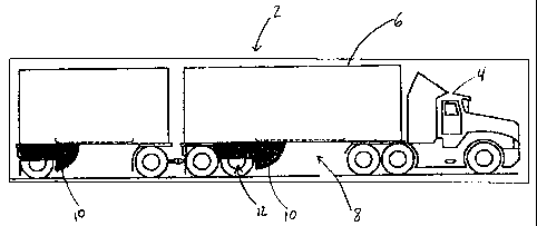
Presented in Fig1 is a powered vehicle 4 depicted as pulling two trailers 6.
Those
skilled in the art will recognize the combination of the powered vehicle 4,
such as a
tractor, pulling a single or multiple trailers 6 as being a semi-trailer 2.
However, it is
important to specify that throughout the present description, the word
"trailer" 6 is
used to incorporate any non-powered vehicle that is pulled by the powered
vehicle 4.
All categories of trailers are being considered, ranging from freight trailers
and utility
trailers that are used to transport cargo, goods and materials, to travel
trailers that
are meant to house people while camping. Furthermore, just as a train can be
made
of wagons that are pulled by a locomotive, multiple trailers can be hitched to
one
another and pulled by the powered vehicle 4.
Conventionally, as the trailer 6 is being pulled, the airflow engulfs in an
underside 8
of the trailer 6. Consequently, due to the presence of a wheel assembly 12,
the
airflow engulfed in the underside 8 of the trailer 6 cannot move freely and
might limit
the forward movement of the trailer 6. Just as the airflow engulfs in the
underside 8
of the trailer 6, elements of the environment such as dirt, rain, snow, ice,
etc. might
also accumulate in the underside 8 of the trailer 6. The accumulation of such
I II MI
1 Y 6
CA 02583852 2007-04-04
elements of the environment might affect break boosters 14, if included in the
wheel-
assernbly 12 as presented in Fig 2a.
To clarify the terminology used in the present description, as presented in
Fig.2a, the
wheel assembly 12 supports the trailer 6. More in detail, as found in Fig.2b,
the
5 wheel assembly 12 is a structure composed of a frame 16 and a suspension 18
to
whichi is attached a wheel axel 22 with wheels 24. Furthermore, as considered
in the
present description, the wheel 24 is an assembly composed of a rim 26 and a
tire 28,
as shown in Fig. 2c.
As depicted in Fig. 1 and more accurately in Fig. 3, a fairing 10 is placed in
front of
the wheel assembly 12 on the underside 8 of the trailer 6. It is important to
add that
the fairing 10 can be placed at any distance from the wheel assembly 12. The
fairing
10 is meant to counteract the effects that the environment has on the trailer
6 or
others. The fairing 10 might counteract the effects of the environment in many
ways
or combination of ways. The following are possible examples of how the fairing
10
could counteract the effects of the environment: First, the fairing 10 can be
designed
to facilitate the forward movement of the trailer 6. By placing the fairing 10
in front of
the wheel assembly 12, the airflow engulfed in the underside 8 of the trailer
6 can be
diverted towards the sides of the trailer 6. Secondly, the fairing 10 might
serve as a
shielci, protecting the components of the wheel assembly 12 from the
environment.
Thirdly, the fairing 10 might prevent side splashes from the wheels 24 to hit
nearby
overtaking vehicles or any possible bystander. It is to be noted that the
fairing 10 can
counteract the effects of the environment also in other ways or combination of
ways
that are not mentioned in the examples above.
In accordance with an aspect of the invention, presented in Fig. 4, an inside
view of
the fairing 10 is shown. The fairing 10 is composed of an outer shell 32, two
side
extensions 34 and a chassis 36. To facilitate the comprehension of how the
fairing 10
might function, the components of the fairing will be described. First, the
shape of the
shell 32, as presented concurrently in Fig. 3, can be designed to influence
the
diversion path of the airflow or can act as a shield to the wheel assembly 12,
consequently protecting it. Second, the side extensions 34 connected to the
shell 32,
i
= ' i i I 1 7.
I.IIM
CA 02583852 2007-04-04
6
could cover the outer sides of the wheels 24, as presented in Fig. 3.
Similarly to the
shell 32, the side extensions 34 can guide the airflow along the side of the
trailer 6
and prevent splashes from the wheels 24 to hit overtaking vehicles or
bystanders.
Thirdly, as the shell 32 and the side extensions 34 might be exposed to strong
winds
and other environmental elements, the shell 32 and side extensions 34 can
require
additional strengthening. In this embodiment, the chassis 36 provides the
additional
strengthening. Furthermore, the chassis 36 could also serve as an attachment
mean
of the fairing 10 to the underside 8 of the trailer 6.
The fairing 10 should not be limited to a literal interpretation of the
components
described above. The fairing 10 might be composed of a combination of elements
or
simply of a single element that might or might not be stated in the aspect of
the
invention. Accordingly, in the case where the fairing 10 is composed of a
combination
of elements, the fairing 10 might be composed of a subset of the elements
stated in
this description. Alternatively, the fairing 10 might be composed of a
combination of a
subset of the elements described in this embodiment with additional elements.
Furthermore, the fairing 10 can be composed of a totally different combination
of
elements then stated in this aspect of the invention.
In this embodiment, when viewed from the outer side, as presented in Fig. 5, a
side
view of the fairing 10 and Fig. 6, a frontal view of the fairing 10, the
fairing 10
displays the shell 32 and side extensions 34. The shell 32 is placed in the
frontal part
of the fairing 10 as to cover a frontal area of the wheel assembly 12 when the
fairing
10 is anchored in place. Accordingly, as presented concurrently in Fig.3, when
the
fairing 10 is put into place on the underside 8 of the trailer 6, the shell 32
is
positioned in front of the wheel assembly 12 and shaped to divert the airflow
and
other environmental effects away from the wheel assembly 12 towards the side
of
the trailer 6. In this embodiment, as the shape of a top portion of a boat
bow, the
shell 32 has a bottom portion 42 that is set back from a top portion 44. As a
result
with such a design, the airflow and environmental effects are diverted towards
the
sides of the trailer 6.
Nw
CA 02583852 2007-04-04
7
It is to be noticed that the shell 32 might be designed to extend transversely
in a
single piece or in multiple pieces, along a width of the wheel assembly 12.
Consequently, when put in place on the underside 8 of the trailer 6, the shell
32, in a
single piece or in multiple pieces, can partially or entirely cover a frontal
area of the
wheel assembly 12. Furthermore, this invention does not limit the fairing 10
to
resenible the top portion of a boat bow, as it can have many other suitable
shapes.
In addition to the possible multiple suitable shapes, the shell 32 may be
fabricated
with various materials, such as fiberglass, metal, metalloid, etc...However,
in an
aspect of the present invention, the shell 32 is built in fiberglass and the
fairing 10 is
composed of light, but durable materials only, so as to add very little weight
to the
trailer 6.
Presented in Fig 3, in accordance with an aspect of the invention, the side
extensions 34 are connected to the outer ends of the shell 32, partially
covering the
wheels 24 on each side of the trailer 6, when the fairing 10 is put into
place. In this
embodiment, the side extension 34 is strengthened by the addition of
longitudinal
ribs 46. Additionally to serving the purpose of guiding the airflow along the
side of the
trailer 6, the side extensions 34 can also restrict side splashes generated
from the
wheels 24 when driving through wet or snowy conditions.
It is to be noticed that the side extension's 34 are optional to the
invention. However,
if side extensions 34 are desired, they can cover partially or entirely the
single wheel
24 or- multiple wheels 24 of the wheel assembly 12. As shown in Fig 5, the
side
extensions 34 can be directly attached to the shell 32, or be a separate
piece.
Furthermore, the side extensions can be a single or a combination of pieces
without
necessarily having the same shape as shown in Figure 5. Additionally, the
longitudinal ribs 46 on the side extensions 34 as found in this embodiment can
be
optional or shaped differently. Alternatively or additionally, the side
extensions 34
migh't be strengthened through a chassis or other means of attachment to the
vehicle.
In this embodiment, to avoid the accumulation of liquids or solids, such as
water or
snow collected from the wheels and dropped into the shell 32, as illustrated
in Fig.7,
. õ .,r,
I I+ 6
CA 02583852 2007-04-04
8
fenders 62 are added to the shell 32. The fenders 62 are placed in an inner
side at
both ends of the shell 32, perpendicularly to the side extensions 34.
Consequently,
the fenders 62 are positioned to partially cover a thread surface of the
wheels 20,
when the fairing is placed into position in front of the wheel assembly 12.
Furthermore, the fenders 62 are equipped with transversal cascading ripples 64
at
their upper portion and water channeling embossment 66 angled downwardly
towards the center of the fenders 62 at their lower portion.
It is to be noticed that the fenders 62 are optional. There may simply be no
means of
avoiding the accumulation of liquids or solids in the fairing 10.
Alternatively, other
means of avoiding the accumulation of liquids or solids in the shell might be
used.
For example, the shell might have a small or large opening in the bottom
preventing
liquids or solids to accumulate. However if present, the fenders 62 might be
shaped
differently. The fender could cover entirely or partially, the full width of
the fairing 10
rather than only the surface of the wheels. Furthermore if present, the
fenders 62 can
be attached differently, for example, they could be attached to the underside
8 of the
trailer 6. It is to be noted that the ripples and embossments allowing water
channeling on the fenders 62 are also optional and can have different shapes.
As the fairing 10 is placed right in front of the wheel assembly 12, for
maintenance
purposes, the access to the components of the wheel assembly 12 can be
difficult. In
this embodiment, as illustrated in Fig.5 and 8, the shell 32, in its top
portion 44, may
be further equipped with an access door 72 giving access to the components of
the
wheel assembly 12.
Notice that the maintenance door 72 is optional. The fairing 10 might simply
not have
any rneans of accessing the wheel assembly 12. Furthermore, the presence of
the
door 72 in the fairing can be for any other reason then for the maintenance of
the
wheel assembly 12. For example, it might be present to access other parts of
the
underside 8 of the trailer 6 or to access the inside of the fairing 10.
Alternatively, if
present, the maintenance door 72 might be shaped or placed differently at
single or
multiple locations.
I IIMIIr.-
I N I IM
CA 02583852 2007-04-04
9
Furthermore, again illustrated in Fig.8, the shell 32 also has a top edge 74
matching
the underside 8 of the trailer 6. As shown in Fig 9, the top edge 74 of the
shell 32
allows anchoring the fairing 10 into place on the underside 8 of the trailer 6
thanks to
an anchoring mechanism 82. The anchoring mechanism 82 can consist of a bolt
and
nut system or of any other means of attaching the top edge 74 of the shell 32
to the
underside 8 of the trailer 6.
Notice that the shape of the top edge 74 might be optional or different. The
top edge
74, if present might not necessarily match the underside 8 of the trailer 6.
For
example, the fairing 10 might be shaped in such a way as to cover only the
bottom
portion of the wheel assembly and might not require matching the underside 8
of the
trailer 6. Furthermore, the top edge 74, if present, might not be used to
anchor the
fairing 10 to the trailer 6. As there are numerous ways that can be thought
for
anchoring the fairing 10 to the underside 8 or other parts of the trailer 6,
the following
are to be considered as possibilities but must not be limited to the following
alternatives.
One alternative is to use the chassis 36 as an attachment means to the
underside 8
of the trailer 6. As presented in Fig. 10, an anchoring mechanism 92 consists
of
connecting the chassis 36 to the underside 8 of the trailer 6 with connecting
rods or
any other means of connection.
Another alternative way of connecting the fairing 10 to the underside 8 of the
trailer 6,
as presented in Fig. 11, is to connect the chassis 36 to the wheel assembly 12
rather
than directly to the underside 8 of the trailer 6, with the means of
connecting rods
102 or any other means of connection. This alternative might be appreciated,
when
the wheel assembly 12 must often be moved, in order to adjust to the weight of
the
goods to be transported.
The present invention has been described with regard to preferred embodiments.
The description as much as the drawings were intended to help the
understanding of
the invention, rather than to limit its scope. It will be apparent to one
skilled in the art
that various modifications may be made to the invention without departing from
the
I I I I N.
CA 02583852 2007-04-04
scope: of the invention as described herein, and such modifications are
intended to
be covered by the present description.
11 1e i IFi