Note: Descriptions are shown in the official language in which they were submitted.
I
CA 02584357 2007-04-05
1
TITLE
Rotary seal for dynamically sealing against a surface of a shaft
FIELD
The present application relates to a rotary seal for dynamically sealing
against a
surface of a shaft.
BACKGROUND
US patent no. 7,052,020 (Kalsi), entitled "Hydrodynamic rotary seal" describes
a
rotary seal that has a sloping dynamic sealing surface that varies in width.
SUMMARY
There is provided a rotary seal for dynamically sealing against a surface of a
shaft,
which includes a seal body having a sealing surface and an outer surface. The
sealing surface
has a first side edge and a second side edge. The sealing surface has discrete
fluid pockets
positioned between the first side edge and the second side edge. The discrete
fluid pockets
tap and use clean lubricating fluid to provide a hydrodynamic film between the
seal surface
and rotating shaft.
13RIEF DESCRIPTION OF THE DRAWINGS
These and other features will become more apparent from the following
description in
which reference is made to the appended drawings, the drawings are for the
purpose of
illustration only and are not intended to be in any way limiting, wherein:
FIG. 1 is a front plan view of a rotary seal.
FIG. 2 is a cross-sectional view of the rotary seal.
FIG. 3 is a detailed rear plan view of the rotary seal engaging a shaft.
FIG. 4 is a detailed view of the contact surface of the rotary seal as it
engages the
shaft surface.
FIG. 5 is a cross-sectional view of an alternative rotary seal.
FIG. 6 is a detailed view of the contact surface of the alternative rotary
seal as it
engages the shaft surface.
FIG. 7 is a cross-sectional view of a further alternative rotary seal.
I ' '
ow,
CA 02584357 2007-04-05
2
FIG. 8 is a detailed view of the contact surface of the further alternative
rotary seal as
it engages the shaft surface.
FIG. 9 and 10 are cross-sectional views of further alternative rotary seals.
FIG. 11 is a side view in section of a rotary seal installed in a seal
housing.
FIG. 12 is a side view in section of a rotary seal built in segmented fashion.
FIG. 13 is a side view in section of a rotary seal built in segmented fashion
and
installed in a seal housing.
FIG. 14 is side view in section of an alternative fluid pocket design in the
sealing
surface.
FIG. 15 is a detailed view of the contact surface of the alternative fluid
pocket design
of the rotary seal as it engages the shaft surface.
DETAILED DESCRIPTION
A rotary seal for dynamically sealing against a surface of a shaft generally
identified
by reference numeral 10, will now be described with reference to FIG. 1
through 14.
Structure and Relationship of Parts:
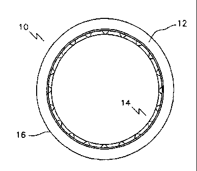
Referring to FIG. 1, rotary seal 10 includes a seal body 12 having a sealing
surface 14
and an outer surface 16. In the description below, the seal body 12 is
described as being
formed of an elastomer. However, any suitable material or combination of
materials known
by those skilled in the art may also be used. Referring to FIG. 11, sealing
surface 14 is
adapted to engage the surface 18 of a shaft 20, such that shaft 20 is
permitted to rotate relative
to seal body 12. Outer surface 16 is adapted to engage a housing 22. While the
description
below describes the shaft as the body that rotates, it will be understood that
the shaft rotation
is relative to the seal and housing. Thus, the shaft could be stationary with
the seal and
housing in rotation. It will also be understood that the seal could be mounted
in the shaft,
rather than the housing as described herein. Furthermore, the term "shaft" is
intended to
describe any substantially cylindrical body that may be sealed by seal 10 in
the manner
described herein.
Referring to FIG. 2, sealing surface 14 has a sealing lip 24 positioned toward
a first
side edge 23 of sealing surface 14. Support ribs 26 extend from sealing lip 24
toward a
'
CA 02584357 2014-01-13
3
second side edge 25 of sealing surface 14. Support ribs 26 are designed to
engage surface 18
of shaft 20. Referring to FIG. 3 and 4, support ribs 26 form discrete fluid
openings 30 for
receiving a second fluid, such as a lubricant. Referring to FIG. 2, sealing
lip 24 is designed to
be equal to or extend below support ribs 26 such that it forms a seal when
rotary seal 10 is
installed on the surface of the shaft (as shown in FIG. 11). Sealing lip 24
seals against a first
fluid, such as an abrasive hydrocarbon flow in an oilfield application.
Referring to FIG. 5 and 7, there may be secondary, or additional sealing lips
32
spaced between sealing lip 24 and second side edge 25 of sealing surface 14.
Referring to
FIG. 6 and 8, sealing lip 24, secondary sealing lips 32 and support ribs 26
form discrete fluid
pockets 28. While three sealing lips 24 and 32 are shown in FIG. 7, it will be
understood that
even more secondary sealing lips 32 may be included to form additional rows of
pockets 28.
The number of rows may be increased in order to accommodate increased
magnitudes of
pressure (described below), with the limitation being the practical length of
the seal.
Referring to FIG. 9 and 10, sealing lips 32 of these shapes may have increased
or
decreased contact pressure with surface 18 of shaft 20 to form fluid pockets
28 as application
and design requires.
Referring to FIG. 4, sealing surface 14 is designed to cause lubricant to
migrate from
second side edge 25 toward first side edge 23. Lubricant gains access to first
side edge 23 by
second side edge 25 by entering openings 30 between support ribs 26. Shaft 20
rotating
relative to sealing surface 14 causes support ribs 26 to apply a migration
force on the second
fluid. By doing so, lubricant lubricates surface 18 of shaft 20 and support
ribs 26 and sealing
lip 24.
Referring to FIG. 6 and 8, which have discrete fluid pockets 28, vibrations
due to
imperfections in the dynamic motion of shaft 20 cause fluctuations in pressure
in fluid
pockets 28. These imperfections may be caused by off-axis rotation, the shaft
having a
slightly elliptical cross-section, or from vibrations due to the drive that
rotates shaft 20.
Similar considerations also cause these fluctuations if housing 22 rotates and
shaft 20 is
stationary. These pockets 28, when filled with clean lubricant, are
essentially incompressible
II I
CA 02584357 2007-04-05
4
fluid reservoirs that "feed" the hydrodynamic fluid film formed between the
sealing lips 24,
32 and support ribs 26 (as well as additional sealing lips 32 when there are
two or more
sealing lips as shown in FIG. 8), and shaft 20. As shaft 20 compresses pockets
28 through its
dynamic run-out, the lubricating oil contained in these pockets experiences an
increase in
pressure. The higher pressure lubricating oil is forced between the tapered
seal lip 24 and
shaft 20. This ensures an enhanced momentary fluid film, or a pulse of higher
pressure
lubricating oil for seal lip 24. As shaft 20 moves away from pockets 28, the
pressure in
pocket 28 decreases and fluid is drawn in. The fluid drawn into fluid pocket
28 will originate
from the direction of the next seal lip 32 because of its shape and
interference on shaft 20.
Thus, each fluid pocket 28 may be considered a "small pump" that ensures a
hydrodynamic
fluid film of clean lubricant fluid from second side edge 25 is maintained
between primary
seal lip 24 and shaft 20.
Alternatives:
As mentioned it will be understood that other designs of sealing lips 24 and
32 may
also be used. As an example, FIG. 9 and 10 show alternate shapes of both
primary seal lip 24
and second seal lip 32 for the embodiment depicted in FIG. 5, which may allow
seal 10 to
achieve better results for particular applications. FIG. 9 shows a variation
of the embodiment
in FIG. 5 with second lip 32 formed in the shape of an "0"-Ring. This example
demonstrates
the variation that is possible with the seal configuration. Traditionally, "0"-
Ring seals do not
perform well in rotary applications due to the distortion of its shape under
pressure and the
contact pressure resulting against the rotating surface 18 of rotating shaft
20. An "0"-Ring
will often be starved of lubrication and the generated heat will result in
over heating of both
the "0"-Ring and rotating surface. When configured in this manner, however, it
may be quite
effective in some applications. FIG. 10 is another variation of FIG. 5 with
second lip 32
formed in the shape of a "B"-Style seal lip. It is known that this shape of
seal lip results in
much higher contact pressures between the seal lip 32 and the rotating surface
18 of shaft 20
and may be desirable in some applications. It will be understood that other
shapes or
combinations of shapes may also be used for a wide range of applications.
Furthermore, while the above description is given in terms of support ribs 26,
it will
be understood that this is merely one way of implementing the design. For
example, the seal
'
I dl Ii lid.
CA 02584357 2007-04-05
footprint, FIG. 4, 6 and 8, or the portion of the seal that contacts the
surface of the shaft, may
be described in terms of circumferential components (or seal lips) and axial
components (or
support ribs), where the axial components need not be perpendicular to the
circumferential
components, and may not have parallel faces. One example may be a footprint
where fluid
5 pockets 28 and/or openings 27 (depending on the embodiment) are formed as
round
depressions in sealing surface 14. Another example is where secondary sealing
lips 32 are not
straight, such that pockets 28 are offset from other adjacent pockets 28.
Furthermore, instead
of considering circumferential and axial components forming the pockets, one
may also talk
in terms of the pockets being formed out of seal surface. FIG. 14 is another
means to achieve
fluid pockets adjacent to sealing lip 24 through the use of a "dimple" design,
similar to the
surface of a golf ball. As can be seen in this embodiment, it is also not
necessary to include
lip 24, however, lip 24 is desirable in most circumstances. Other designs
using these
principles will be apparent to those skilled in the art
Referring to FIG. 12 and 13, other advantages may be had by building seal 10
in a
segmented fashion and then using seals 10 in a stacked seal arrangement. In
this situation,
pockets 28 may be formed between primary seal lip 24 of one seal body 12, and
openings 30
of another seal body 12 that meet appropriately when subjected to pressure.
Advantages:
Some considerations that are incorporated in this design include: a
compressive
mounting of the seal onto the shaft, a tapered lip style to create the barrier
between the
abrasive fluid and the clean lubricating fluid, a displaced seal lip to
prevent "nibbling" from
the gland, and ensuring a hydrodynamic fluid film between the elastomer seal
and rotating
shaft for varied pressure conditions.
It is generally a combination of applied pressure and friction that is related
to the
speed of the rotating shaft that limits the performance of an elastomer seal.
To reduce the heat
generated, a compressive mounting may be used, where the seal is slightly
larger than the
shaft, and then compressed onto the rotatable surface 18 through proper sizing
of seal groove
16 in housing 22.
CA 02584357 2007-04-05
6
In providing a hydrodynamic film, the friction between the seal and the
surface of the
shaft may be reduced. Referring to the embodiment shown in FIG. 2, 3 and 4,
seal 10
consists of tapered seal lip 24 that is set back from first side edge 23 of
sealing surface 14,
(seal lip 24 is set back is to prevent "nibbling" from the gland to shaft
clearance). Support ribs
26 remain open to the lubricating fluid supplied opposite the fluid to be
sealed. Each rib 26 is
in contact with shaft 20, (shown in FIG. 11), and provides a constant "wiping"
of fluid off
shaft 20 as shaft 20 rotates. Advantages to this design are control of the
hydrodynamic film
through differences in shaft interference of tapered seal lip 24 and ribs 26,
as well as the
number of ribs 26 provided in each seal 10. As with many seal designs, the
performance of
this design may be limited by the magnitude of the contained pressure due to
the tendency of
an elastomer to deform under pressure. However, the rib design offers
resistance to this
deformation. In addition, fluid pockets 28 such as shown in FIG. 6 and 8, also
provide
structural support to resist deformation when filled with incompressible
lubricant.
One of the key design features of seal 10 is the provision of a means to trap
clean
lubricating oil in small pockets 28 behind primary seal lip 24. When axial
pressure is applied
to seal body 12, the oil trapped in pockets 28 is subjected to same pressure
as the elastomer.
Because the oil is substantially incompressible, it maintains its presence and
provides an
amount of lubricant directly to primary seal lip 24. This helps prevent
starving the elastomer
of a hydrodynamic film as pressures increase. Ribs 26 also tend to support the
structure of
pockets 28 and provide inlet means 27 for the clean lubricants. Given the
benefits of this
feature, the performance of seal 10 in different pressure situations will now
be discussed with
reference to the embodiment shown in FIG. 5 and 6. Similar considerations may
be applied
to the other embodiments discussed.
In the high-pressure hydraulic lubricant condition, the pressure of the second
fluid,
usually the clean lubricant, is greater than the pressure of the abrasive
contaminated fluid. In
this case, second seal lip 32 and ribs 26 that form pockets 28 on the high-
pressure side of
primary seal lip 24 serve many purposes:
- Second seal lip 32 and ribs 26 provide a hydrodynamic film mechanism for
lubrication to prevent heat generation between seal surface 14 and rotatable
surface
18.
' " I
CA 02584357 2007-04-05
'7
- Second
seal lip 32 is shaped to allow clean secondary lubricating fluid leakage in a
direction towards first seal lip 24 for lubrication of first seal lip 24 and
exclusion of
the abrasive first fluid.
- Fluid
pockets 28 of lubricating fluid behind primary seal lip 24 prevent applied
axial
pressure from deforming seal body 12 to the point that the contact area
between seal
surface 14 and rotating shaft surface 18 is starved of lubricating oil. As
axial pressure,
acting on seal body 12 increases, the resulting pressure applied to rotating
shaft
surface 18 from seal surface 14 increases. The pressure of the clean lubricant
trapped
in the pockets also increases at the same magnitude and, being virtually
incompressible, maintains the structure of the pocket 28 as well as provide a
presence
of clean lubricating fluid under pressure to lubricate the seal surface 14.
This configuration, along with the mechanical "pumping" action of shaft 20,
ensures that
pockets 28 remain full of lubricating fluid to provide the "pulsed" hydraulic
fluid film
between primary seal lip 24 and shaft surface 18.
In the balanced hydraulic lubricant condition, the clean hydraulic lubricant
fluid
pressure is equal to the pressure of the abrasive contaminated fluid. This may
be the ideal
condition for seal 10. With equal pressure on either side of seal body 12,
ribs 26 provide
lubricant openings 27 for the hydrodynamic film. This, in combination with the
dynamic
imperfections of the shaft rotation, acting on fluid pockets 28, may provide
the appropriate
amount of lubricant to primary seal lip 24 for higher speeds. This is
beneficial because
reducing the applied pressure on an elastomer seal allows the seal to be used
more
successfully at higher speeds.
FIG. 1 shows a seal body 12 with an opening and 20 ribs 26. However, the
number
of ribs may be changed in order to vary the size of sealed pockets 28, and the
number of
contact points on shaft 20. These are significant variables in application due
to the two
hydrodynamic mechanisms to be considered. Firstly, the number and shape of
ribs 26 will
determine the amount of lubricating fluid supplied to the hydrodynamic film.
Secondly, the
number and size of fluid pockets 28 will directly affect the magnitude of the
"pulse" resulting
from rotating shaft 20. For example, fewer ribs 26 results in larger fluid
pockets 28 with less
pulse magnitude from shaft inconsistencies. Conversely, more ribs 28 results
in smaller fluid
I I
I
II I 1111-
CA 02584357 2007-04-05
8
pockets 28 that may prove to be extremely sensitive to shaft dynamics. If each
pocket 28 is
considered a small "pump", a fluid reservoir could be emptied too quickly with
an
inappropriate design or application.
In the balanced lubricant condition, some insight into what can be done
through the
design aspect of seal 10 may be gained. The necessary condition for success is
to ensure that
primary seal lip 24 is provided with a hydrodynamic film of clean lubricant.
In the reverse
pressure condition, therefore, the pressure of the clean lubricant fluid must
be greater than the
pressure of the abrasive contaminated fluid. Pockets 28 of clean lubricant in
this design and
the dynamic inconsistencies of the shaft rotation provide a mechanism to
increase the pressure
of the clean lubricating fluid. The magnitude of the pressure increase is
influenced by many
factors, including specific applications, and requires testing to determine
its effectiveness.
In the reverse pressure condition, the clean hydraulic lubricant fluid
pressure is less
than the pressure of the abrasive contaminated fluid. This condition is the
most difficult to
accommodate successfully. It should be recognized, however that seal 10 does
not have the
same inherent problems associated with other designs. With primary seal lip
and support ribs,
FIG. 2, reverse pressure conditions do not deform seal body 12 to produce
pressure pivots or
high and low-pressure contact areas in seal surface 14 due to the supporting
rib structure. In
the sealed pocket design, FIG. 5 and 7, the fluid filled pressure pockets 28
further resist
reverse pressure conditions. Compression of seal body 12 in the reverse
pressure condition
results in compression of the clean lubricating oil sealed in pockets 28
behind primary seal lip
24. As in the high-pressure lubricant condition, sealed pockets 28 reduce the
area of high-
pressure contact between the elastomer and rotating shaft 20 by sealed pockets
28 of
incompressible lubricant.
In this patent document, the word "comprising" is used in its non-limiting
sense to
mean that items following the word are included, but items not specifically
mentioned are not
excluded. A reference to an element by the indefinite article "a" does not
exclude the
possibility that more than one of the element is present, unless the context
clearly requires that
there be one and only one of the elements.
,
I 11 1413i
CA 02584357 2007-04-05
9
It will be apparent to one skilled in the art that modifications may be made
to the
illustrated embodiment without departing from the spirit and scope defirted in
the Claims.
I t