Language selection

Search

Patent 2584473 Summary

Third-party information liability

Some of the information on this Web page has been provided by external sources. The Government of Canada is not responsible for the accuracy, reliability or currency of the information supplied by external sources. Users wishing to rely upon this information should consult directly with the source of the information. Content provided by external sources is not subject to official languages, privacy and accessibility requirements.

Claims and Abstract availability

Any discrepancies in the text and image of the Claims and Abstract are due to differing posting times. Text of the Claims and Abstract are posted:

  • At the time the application is open to public inspection;
  • At the time of issue of the patent (grant).
(12) Patent Application: (11) CA 2584473
(54) English Title: LIQUID MIXTURE DISPENSING SYSTEM
(54) French Title: SYSTEME DE DISTRIBUTION DE MELANGE LIQUIDE
Status: Deemed Abandoned and Beyond the Period of Reinstatement - Pending Response to Notice of Disregarded Communication
Bibliographic Data
(51) International Patent Classification (IPC):
  • B67D 1/00 (2006.01)
  • B67D 1/04 (2006.01)
(72) Inventors :
  • NEWTON, JOHN R. (United States of America)
(73) Owners :
  • GLOBAL AGRICULTURAL TECHNOLOGY AND ENGINEERING, LLC
(71) Applicants :
  • GLOBAL AGRICULTURAL TECHNOLOGY AND ENGINEERING, LLC (United States of America)
(74) Agent: SMART & BIGGAR LP
(74) Associate agent:
(45) Issued:
(86) PCT Filing Date: 2005-10-11
(87) Open to Public Inspection: 2006-05-04
Examination requested: 2007-09-21
Availability of licence: N/A
Dedicated to the Public: N/A
(25) Language of filing: English

Patent Cooperation Treaty (PCT): Yes
(86) PCT Filing Number: PCT/US2005/036481
(87) International Publication Number: WO 2006047083
(85) National Entry: 2007-04-18

(30) Application Priority Data:
Application No. Country/Territory Date
60/620,505 (United States of America) 2004-10-21
60/636,044 (United States of America) 2004-12-14

Abstracts

English Abstract


A liquid dispensing system comprises a container (112) containing at least one
flexible bag (14, 16). A first liquid (18, 20) is contained in the bag. A
manifold chamber (24) is in communication with the bag via a first metering
orifice (26, 28), and with the interior of the container (12) via a second
metering orifice (41). A second liquid (38) is introduced under pressure into
the container. The thus introduced second liquid serves to pressurize the
first liquid in the bag, with the first and second metering orifices serving
to respectively admit metered amounts of the first and second liquids into the
manifold chamber for combination into a liquid mixture dispensed through an
outlet (42).


French Abstract

Cette invention concerne un système de distribution de liquide comprenant un récipient (112) contenant au moins un sac souple (14, 16). Le sac contient un premier liquide (18, 20). Une chambre de collecte (24) communique avec le sac par l'intermédiaire d'un premier orifice de dosage (26, 28) et avec l'intérieur du récipient (12) par l'intermédiaire d'un second orifice de dosage (41). Un second liquide (38) est introduit sous pression dans le récipient. Le second liquide ainsi introduit sert à mettre le premier liquide sous pression dans le sac, le premier et le second orifice de dosage servant respectivement à laisser entrer des quantités dosées du premier et du second liquide dans la chambre de collecte afin qu'ils soient combinés en un mélange liquide distribué par un orifice d'évacuation (42).

Claims

Note: Claims are shown in the official language in which they were submitted.

1. A liquid dispensing system comprising:
a container;
at least one flexible bag in said container;
a first liquid contained in said bag;
a manifold chamber having an outlet, said manifold chamber being in
communication with said bag via a first metering orifice, and being in
communication
with the interior of said container via a second metering orifice; and
supply means for introducing a second liquid under pressure into said
container,
the thus introduced second liquid serving to pressurize the first liquid in
said bag, with
said first and second metering orifices serving to respectively admit metered
amounts of
said pressurized first and second liquids into said manifold chamber for
combination into
a liquid mixture dispensed through said outlet.
2. The liquid dispensing system of claim 1 wherein said container has an
opening
through which said bag is received, and wherein said manifold chamber is
incorporated in
a cap closing said opening.
3. The liquid dispensing system of claim 1 wherein multiple flexible bags are
enclosed in said container, each of said bags containing first liquids, and
each of said
bags being in communication with said manifold chamber via respective first
metering orifices.
4. The liquid dispensing system of claim 1 wherein said supply means includes
a
first valve for maintaining the second liquid introduced into said container
at a
substantially constant pressure.

5. The liquid dispensing system of claim 4 wherein the flow of said liquid
mixture dispensed through said outlet is controlled by a second valve.
6. The liquid dispensing system of claim 5 wherein said container and said
manifold comprise an integral unit detachably connected to said first and
second
valves by separable couplings.
7. A liquid dispensing system comprising:
a container having an open top;
a plurality of flexible bags received in said container via said open top;
first liquid components contained in said bags;
a cap closing said open top, said cap defining a manifold chamber having an
outlet, said manifold chamber being in communication with said bags via first
metering orifices, and being in communication with the interior of said
container via a second metering orifice; and
supply means for introducing a second liquid component at a substantially
constant pressure into said container, the thus introduced second liquid
component
serving to pressurize the first liquid components in said bags, with said
first and
second metering orifices serving to respectively admit metered amounts of said
first
and second liquid components into said manifold chamber for combination into a
liquid mixture dispensed from said manifold chamber through said outlet.
6

Description

Note: Descriptions are shown in the official language in which they were submitted.


CA 02584473 2007-04-18
WO 2006/047083 PCT/US2005/036481
LIQUID MIXTURE DISPENSING SYSTEM
REFERENCE TO RELATED APPLICATION
This application claims priority from Provisional Patent Application Nos.
60/620,505 filed 10/21/2004 and 60/636,044 filed 12/14/2004.
BACKGROUND DISCUSSION
1. Field of the Invention
This invention relates to liquid dispensing systems employing self-emptying
containers.
2. Description of Prior Art
It is known to enclose liquid-containing flexible bags or pouches in
relatively
rigid containers, and to pressurize the containers to expel the liquids
through metering
orifices or the like. Conventionally, the containers are pressurized by liquid
or
gaseous mediums that vary in pressure and that are isolated from the liquids
being
dispensed.
SUMMARY OF THE INVENTION
The present invention departs from this conventional approach by enclosing in
a container one or more flexible bags containing liquid components, with the
bags and
the container interior communicating with a manifold chamber via appropriately
sized
metering orifices. A liquid pressurizing medium is introduced at a
substantially
constant pressure into the container, where it serves to collapse the bags and
expel
metered amounts of their respective liquid components to the manifold chamber,
1

CA 02584473 2007-04-18
WO 2006/047083 PCT/US2005/036481
along with a metered amount of the pressuring liquid. The metered liquid
amounts
are combined in the manifold chamber and delivered as a mixture.
BRIEF DESCRIPTION OF THE DRAWING
The present invention will now be described in further detail with reference
to
the accompanying drawing schematically depicting a preferred embodiment.
DETAILED DESCRIPTION
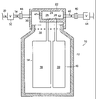
With reference to the drawing, a dispensing system for liquid mixture products
(e.g., tea, fruit based drinks, etc.) includes a disposable unit 10 having an
outer
container 12. In one example, container 12 could comprise a standard one-liter
plastic
bottle of the type now usually used to contain soft drinks and the like.
Container 12
encloses at least one, and preferably a plurality of flexible plastic bags 14
and 16 that
contain liquid components 18 and 20, respectively, of a desired end product.
In one
example, bag 14 contains a tea concentrate syrup and bag 16 contains a
fragrance
essence. Container 12 has an open top through which the bags 14, 16 are
received. A
cap 22 closes the open container top. Cap 22 is attached to container 12, such
as by
threads or solvent welding. Bags 14 and 16 are in communication with a
manifold
chamber 24 fonned within cap 22, via metering orifices 26 and 28. When bags 14
and 16 are pressurized, as described in more detail below, metered amounts of
the
liquid components 18 and 20 are delivered via the orifices 26, 28 into
manifold
chamber 24.
A supply means, typically a municipal water supply 30 is connected to cap 22
via a normally closed constant flow valve 32. Typically, the pressure of any
municipal water supply will vary widely. Constant flow valve 32 isolates unit
10
2

CA 02584473 2007-04-18
WO 2006/047083 PCT/US2005/036481
from such variations by remaining open and maintaining a substantially
constant
selected flow and pressure downstream of valve 32 as long as the pressure of
supply
30 remains above a threshold level. If the pressure of supply 30 falls below
the
threshold level, valve 32 closes automatically. In one example, constant flow
valve
32 maintains a substantially constant flow of water 34 at three ounces per
second
while supply 30 varies in pressure from at least about 20 pounds per square
inch to
about 95 pounds per square inch. Examples of such normally closed constant
flow
valves are described in U.S. Patent No. 6,026,850 and U.S. Patent No.
6,209,578, the
disclosures of which are incorporated herein by reference.
Water 34 flows from valve 32, through passageway 36 formed in cap 22, into
the interior 38 of container 12. Water 34 fills and pressurizes interior 38 to
about 12
psi, for example, resulting in two events. First, water 34 exerts pressure on
bags 14
and 16 and expels liquid components 18 and 20 into chamber 24 via metering
orifices
26 and 28. Because the pressure exerted by water 34 on bags 14 and 16 is
uniform,
bags 14 and 16 do not require high strength seams. Second, water 34 flows into
manifold chamber 24 via a metering orifice 41. The metered amounts of the
liquid
components 18 and 20 and water 34 mix in chamber 24 to form the desired liquid
mixture 40, such as a soft driiik. The proportions of liquid components 18 and
20 and
water 34 in mixture 40 are determined by the size of the metering orifices 26,
28, and
41, respectively, and the operating pressure of the water 34, which is
maintained at a
substantially constant level by valve 32. In one example, water 34 is mixed
with a
concentrate syrup at a ratio of about 150:1 and with a concentrate essence at
a ratio of
about 500:1. In another example, concentrate syrup flows into chamber 24 at
about
6.0 cc/sec and concentrate essence 20 flows into chamber 24 at about 0.2
cc/sec. The
3

CA 02584473 2007-04-18
WO 2006/047083 PCT/US2005/036481
resulting liquid mixture 40 flows out of the manifold chamber 24 through
outlet
passageway 42 and is dispensed via a solenoid controlled valve 44.
When either bag 14 or bag 16 is empty, container unit 10 may simply be
disconnected from constant flow valve 32 and valve 44 by diy disconnect
couplings
46, discarded and replaced by re-connecting the couplings 46 to a fresh unit.
The
units remain sealed at all times, thus safeguarding the bags 14, 16 and their
contents
from exposure to external contaminants as one unit is exchanged for another.
I claim:
4

Representative Drawing
A single figure which represents the drawing illustrating the invention.
Administrative Status

2024-08-01:As part of the Next Generation Patents (NGP) transition, the Canadian Patents Database (CPD) now contains a more detailed Event History, which replicates the Event Log of our new back-office solution.

Please note that "Inactive:" events refers to events no longer in use in our new back-office solution.

For a clearer understanding of the status of the application/patent presented on this page, the site Disclaimer , as well as the definitions for Patent , Event History , Maintenance Fee  and Payment History  should be consulted.

Event History

Description Date
Time Limit for Reversal Expired 2010-10-12
Application Not Reinstated by Deadline 2010-10-12
Deemed Abandoned - Failure to Respond to Maintenance Fee Notice 2009-10-13
Letter Sent 2007-10-22
Request for Examination Received 2007-09-21
Request for Examination Requirements Determined Compliant 2007-09-21
All Requirements for Examination Determined Compliant 2007-09-21
Letter Sent 2007-09-11
Inactive: Single transfer 2007-07-13
Inactive: Cover page published 2007-07-03
Inactive: Incomplete PCT application letter 2007-06-29
Inactive: Notice - National entry - No RFE 2007-06-29
Inactive: First IPC assigned 2007-05-10
Application Received - PCT 2007-05-09
National Entry Requirements Determined Compliant 2007-04-18
Application Published (Open to Public Inspection) 2006-05-04

Abandonment History

Abandonment Date Reason Reinstatement Date
2009-10-13

Maintenance Fee

The last payment was received on 2008-09-30

Note : If the full payment has not been received on or before the date indicated, a further fee may be required which may be one of the following

  • the reinstatement fee;
  • the late payment fee; or
  • additional fee to reverse deemed expiry.

Please refer to the CIPO Patent Fees web page to see all current fee amounts.

Fee History

Fee Type Anniversary Year Due Date Paid Date
Basic national fee - standard 2007-04-18
Registration of a document 2007-07-13
Request for examination - standard 2007-09-21
MF (application, 2nd anniv.) - standard 02 2007-10-11 2007-09-27
MF (application, 3rd anniv.) - standard 03 2008-10-14 2008-09-30
Owners on Record

Note: Records showing the ownership history in alphabetical order.

Current Owners on Record
GLOBAL AGRICULTURAL TECHNOLOGY AND ENGINEERING, LLC
Past Owners on Record
JOHN R. NEWTON
Past Owners that do not appear in the "Owners on Record" listing will appear in other documentation within the application.
Documents

To view selected files, please enter reCAPTCHA code :


To view images, click a link in the Document Description column. To download the documents, select one or more checkboxes in the first column and then click the "Download Selected in PDF format (Zip Archive)" or the "Download Selected as Single PDF" button.

List of published and non-published patent-specific documents on the CPD .

If you have any difficulty accessing content, you can call the Client Service Centre at 1-866-997-1936 or send them an e-mail at CIPO Client Service Centre.


Document
Description 
Date
(yyyy-mm-dd) 
Number of pages   Size of Image (KB) 
Drawings 2007-04-18 1 20
Claims 2007-04-18 2 66
Description 2007-04-18 4 132
Abstract 2007-04-18 2 75
Representative drawing 2007-07-03 1 13
Cover Page 2007-07-03 1 45
Reminder of maintenance fee due 2007-07-03 1 112
Notice of National Entry 2007-06-29 1 195
Courtesy - Certificate of registration (related document(s)) 2007-09-11 1 129
Acknowledgement of Request for Examination 2007-10-22 1 177
Courtesy - Abandonment Letter (Maintenance Fee) 2009-12-08 1 172
PCT 2007-04-18 3 86
Correspondence 2007-06-29 1 17
Fees 2007-09-27 1 44