Note: Descriptions are shown in the official language in which they were submitted.
CA 02584952 2007-04-16
SAFETY VALVE HAVING MONO SPRING CLOSURE MECHANISM
BACKGROUND
The present invention relates generally to equipment
utilized and operations performed in conjunction with
subterranean wells and, in an embodiment described
herein, more particularly provides a safety valve having
a mono spring closure mechanism.
It is desirable to provide a safety valve which has
an increased inner diameter/outer diameter ratio. This
is due to the restricted confines of a wellbore and the
desire to have a large flow area for production of fluids
from the wellbore. For these reasons it is also
desirable to provide a safety valve closure mechanism
which can be accommodated in a reduced thickness sidewall
area, while still enabling the safety valve to be
effectively and reliably closed when necessary.
In the past, safety valve designers have tried using
multiple springs in closure mechanisms, in order to
provide sufficient force to operate the closure
mechanisms in reduced thickness sidewalls. Some of these
designs have been successful. However, the use of
multiple springs increases the complexity of a closure
mechanism while reducing reliability (due to multiple
moving elements, increased possibility that debris could
impair operation of one of the elements, etc.) and
increasing the cost of the closure mechanism.
Therefore, it may be seen that improvements are
needed in the art of safety valve closure mechanisms. It
is among the objects of the present invention to provide
such improvements.
- 1 -
CA 02584952 2009-01-19
SUMMARY
In carrying out the principles of the present invention, a safety valve is
provided with a closure mechanism which solves at least one problem in the
art. One
example is described below in which the closure mechanism is able to fit into
a
reduced thickness sidewall of the safety valve. Another example is described
below
in which a single spring is used to close the closure mechanism.
In one aspect of the invention, a safety valve is provided which includes a
closure mechanism with no spiral wound springs. Preferably only a single
spring is
used which includes beam legs to bias a closure member toward its closed
position.
In another aspect of the invention, a safety valve is provided with a closure
mechanism including a spring having a beam which bends along its length to
bias a
closure member toward a fully closed position in which flow through a passage
of the
safety valve is prevented. The beam applies a biasing force to the closure
member at
the fully closed position and at a fully open position of the closure member
in which
maximum flow through the passage is permitted.
In yet another aspect of the invention, a safety valve is provided with a
closure mechanism including only a single spring. The spring has at least two
legs,
with the legs being joined to each other at an end of each leg. Each leg
includes at
least one beam.
In another aspect of the invention, there is provided a safety valve for use
in a
subterranean well, the safety valve comprising: a closure mechanism including
a
spring, the spring including at least one leg which has a progressively
reduced cross-
sectional area along a majority of its length.
In a still further aspect of the invention, there is provided a safety valve
for
use in a subterranean well, the safety valve comprising: a closure mechanism
including a spring having a leg which bends along its length to bias a closure
member
toward a fully closed position in which flow through a passage of the safety
valve is
prevented, the leg applying a biasing force to the closure member at the fully
closed
position and at a fully open position of the closure member in which
-2-
CA 02584952 2009-01-19
maximum flow through the passage is permitted, and wherein the entire spring
rotates as the closure member rotates.
In a still further aspect of the invention, there is provided a safety valve
for
use in a subterranean well, the safety valve comprising: a closure mechanism
including a closure member having a fully closed position, and the closure
member
further including a spring with at least one beam which applies a biasing
force to the
closure member due to deformation of the beam at the fully closed position.
These and other features, advantages, benefits and objects of the present
invention will become apparent to
2a-
CA 02584952 2007-04-16
one of ordinary skill in the art upon careful
consideration of the detailed description of
representative embodiments of the invention hereinbelow
and the accompanying drawings, in which similar elements
are indicated in the various figures using the same
reference numbers.
BRIEF DESCRIPTION OF THE DRAWINGS
FIG. 1 is a partially cross-sectional schematic
elevational view of a well system embodying principles of
the present invention;
FIG. 2 is an enlarged scale cross-sectional view
through a portion of a safety valve in the well system of
FIG. 1, wherein a closure mechanism of the safety valve
is depicted in a fully open configuration;
FIG. 3 is a cross-sectional view of the portion of
the safety valve of FIG. 2, wherein the closure mechanism
is depicted in a partially open configuration;
FIG. 4 is a cross-sectional view of the portion of
the safety valve of FIG. 2, wherein the closure mechanism
is depicted in a fully closed configuration;
FIG. 5 is an enlarged scale elevational view of a
first alternate configuration of a spring for use in the
closure mechanism;
FIG. 6 is an isometric view of a second alternate
configuration of the spring;
FIG. 7 is an isometric view of a third alternate
configuration of the spring;
FIG. 8 is an elevational view of a fourth alternate
configuration of the spring; and
- 3 -
CA 02584952 2007-04-16
FIG. 9 is an elevational view of a fifth alternate
configuration of the spring.
DETAILED DESCRIPTION
It is to be understood that the various embodiments
of the present invention described herein may be utilized
in various orientations, such as inclined, inverted,
horizontal, vertical, etc., and in various
configurations, without departing from the principles of
the present invention. The embodiments are described
merely as examples of useful applications of the
principles of the invention, which is not limited to any
specific details of these embodiments.
In the following description of the representative
embodiments of the invention, directional terms, such as
"above", "below", "upper", "lower", etc., are used for
convenience in referring to the accompanying drawings.
In general, "above", "upper", "upward" and similar terms
refer to a direction toward the earth's surface along a
wellbore, and "below", "lower", "downward" and similar
terms refer to a direction away from the earth's surface
along the wellbore.
Representatively illustrated in FIG. 1 is a well
system 10 which embodies principles of the present
invention. A tubular string 12 (such as a production
tubing string) has been installed in a wellbore 14. The
tubular string 12 has a flow passage 16 extending
longitudinally through it for production of fluids from
the wellbore 14.
A safety valve 18 is interconnected in the tubular
string 12 for control of the flow of fluids through the
- 4 -
CA 02584952 2007-04-16
passage 16. In particular, the safety valve 18 operates
to prevent uncontrolled flow of fluids through the
passage 16, for example, to prevent a blowout. The
safety valve 18 may be operated for other purposes, as
well.
A control line 20 is used to operate the safety
valve 18. Typically, the control line 20 is a hydraulic
control line, but other types of control lines (such as
optical, electrical, etc.) may be used, depending upon
the type of actuator with which the safety valve 18 is
equipped. Of course, the control line 20 is not always
necessary, since the safety valve 18 could instead be
operated via any type of telemetry (such as
electromagnetic, acoustic, pressure pulse, etc.).
It should be clearly understood that the principles
of the invention are not limited in any way to the
details of the well system 10 described above. Instead,
the well system 10 is merely one example of an
application of the principles of the invention. Other
types of well systems, and other types of safety valves,
may be used without departing from the principles of the
invention.
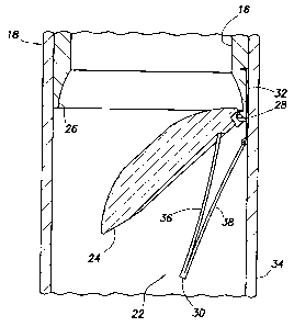
Referring additionally now to FIG. 2, a closure
mechanism 22 of the safety valve 18 is representatively
illustrated in cross-section. The closure mechanism 22
includes a flapper closure member 24 and a seat 26. The
flow passage 16 extends through the seat 26 and, with the
closure member 24 in the position depicted in FIG. 2,
flow through the closure mechanism 22 is permitted.
In this open configuration of the closure mechanism
22, a conventional flow tube, opening prong (not shown)
or other device would maintain the closure member 24
- 5 -
CA 02584952 2007-04-16
rotated downward about a pivot 28. In this manner, the
closure member 24 is maintained in a sidewall area of the
safety valve 18.
It will be appreciated that space is limited in the
sidewall area of the safety valve 18, and so the
mechanism for pivoting the closure member 24 about the
pivot 28 should be relatively small in size, while still
being able to exert sufficient force to effectively close
off flow through the passage 16 (by engaging the closure
member with the seat 26). Furthermore, the pivoting
mechanism should be reliable in operation and, therefore,
should preferably have a minimum number of moving
elements.
In the embodiment depicted in FIG. 2, the closure
mechanism 22 includes a spring 30 positioned between the
closure member 24 and an outer housing 34 of the safety
valve 18. The spring 30 has two longitudinally extending
inner and outer legs or beams 36, 38 joined to each other
at one end.
The other end of the outer beam 38 is secured in
place relative to the outer housing 34 by an anchor
device 32. In this example, the anchor device 32 is a
formed wire which is inserted at one end into a recess on
an exterior of the seat 26. The other end of the anchor
device 32 is wrapped about the upper end of the outer
beam 38, thereby securing the upper end of the beam to
the seat 26.
The upper end of the inner beam 36 is in contact
with the closure member 24 and exerts a biasing force
against the closure member. This biasing force tends to
rotate the closure member 24 upward (or clockwise as
- 6 -
CA 02584952 2007-04-16
viewed in FIG. 2) about the pivot 28 and toward the seat
26.
The flow tube or opening prong discussed above is
used to counteract this biasing force and maintain the
closure member 24 in its downwardly pivoted position as
shown in FIG. 2. This is the fully open position of the
closure member 24, in which maximum flow through the
passage 16 is permitted.
Although as depicted in FIG. 2 each of the beams 36,
38 appears to be relatively straight, the beams only have
this shape due to their being compressed between the
closure member 24 and the outer housing 34. When they
are free of this compression, the beams 36, 38 assume a
curved shape described more fully below.
Referring additionally now to FIG. 3, the closure
mechanism 22 is representatively illustrated in a
partially open (or partially closed) configuration. In
this configuration, the flow tube or opening prong
discussed above permits some upward rotation of the
closure member 24 about the pivot 28.
Note that the upper ends of the beams 36, 38 have
now spread apart due to the rotation of the closure
member 24. It will be appreciated that, since the point
of contact between the upper end of the inner beam 36 has
now displaced inward relative to the pivot 28, somewhat
less torque or moment is applied to the closure member 24
by the spring 30 as compared to the open configuration of
FIG. 2.
Thus, greater torque is applied to the closure
member 24 when rotation of the closure member about the
pivot 28 is initiated, and the torque decreases as the
closure member pivots upward toward the seat 26. This is
- 7 -
CA 02584952 2007-04-16
a desirable feature of the closure mechanism 22, since
greater torque is typically needed to initiate rotation,
as compared to the torque needed to maintain the rotation
after it has been initiated.
Note that the spring 30 rotates as the closure
member 24 rotates. This may be seen by comparing FIGS. 2
& 3 and observing that the joined lower ends of the beams
36, 38 have rotated upward as the closure member 24 has
rotated upward.
The relative rotation between the closure member 24
and the beams 36, 38 is a function of many variables,
among which are the length of each beam and the distance
from the upper end of each beam to the pivot 28. By
manipulating these variables, the magnitude and direction
of the biasing force applied to the closure member 24 by
the spring 30 at various points in the rotation of the
closure member can be adjusted to thereby adjust the
torque applied to the closure member.
Another reason the torque applied to the closure
member 24 decreases as it rotates upward is that the
biasing force exerted by the spring 30 on the closure
member decreases somewhat as the upper ends of the beams
36, 38 spread apart. This is due to the characteristic
of the spring 30 known to those skilled in the art as a
spring rate (load/deflection). Various techniques may be
used to maintain a sufficiently large biasing force to
effectively and reliably rotate the closure member 24
upward, and some of these techniques are discussed below.
The length, thickness, width and material of which
the beams 36, 38 are made will affect the spring rate
and, thus, the biasing force and torque applied to the
closure member 24. It is not necessary for the beams 36,
- 8 -
CA 02584952 2007-04-16
38 to have constant thickness, width or material
properties since, for example, it may be most efficient
to provide greater material strength and elasticity
and/or greater material volume and/or greater moment of
inertia in portions of the beams subjected to greater
stress.
Note that each of the beams 36, 38 is thicker at its
lower end since, in this example, the lower ends of the
beams are subjected to greater bending stress than the
upper ends of the beams. In addition, the spring 30 is
preferably integrally formed of a single piece of
material. The spring 30 could be formed, for example,
using EDM manufacturing techniques. Alternatively, the
spring 30 could be formed from multiple pieces of
material, with the lower ends of the beams 36, 38 joined
using any technique (such as welding, clamping, bonding,
wire wrapping, composite wrapping, fastening with rivets,
screws, bolts, pins, etc.).
Referring additionally now to FIG. 4, the closure
mechanism 22 is representatively illustrated with the
closure member 24 rotated upward sufficiently far to
sealingly engage the seat 26. In this configuration,
flow through the passage 16 is prevented. This is the
fully closed position of the closure member 24.
The spring 30 continues to apply a biasing force to
the closure member 24, since the spring remains somewhat
compressed. Note that the spring 30 has rotated further
upward as compared to the configuration depicted in FIG.
3.
Referring additionally now to FIG. 5, an alternate
construction of a spring 40 which may be used in place of
the spring 30 in the closure mechanism 22 is
9 -
CA 02584952 2007-04-16
representatively illustrated. The spring 40 is shown in
an uncompressed state.
The spring 40 is similar in some respects to the
spring 30. The spring 40 is formed of a single piece of
material, and it has two legs 50, 52 which curve outward
from each other toward their upper ends. However, it
should be clearly understood that the spring 40 could be
formed of multiple pieces of material and could be
otherwise configured, in keeping with the principles of
the invention.
One difference between the springs 30, 40 is that
the spring 40 includes multiple beams 42, 44, 46, 48 in
each of its legs 50, 52. It will be appreciated by those
skilled in the art that the use of multiple beams
(instead of a single beam having an equivalent width,
thickness and length) in each of the legs 50, 52 reduces
the bending stresses in the beams for the same amount of
deflection, at least in part due to the fact that shear
stress is not transferred between the multiple beams.
Stated differently, for a given level of bending stress,
greater deflection is obtained by using multiple beams as
compared to using a single beam of equivalent width,
thickness and length.
Each of the beams 42, 44, 46, 48 of the spring 40
has a progressively reduced thickness from its lower end
to its upper end, similar to the beams 36, 38 of the
spring 30. As with the spring 30, the spring 40 may have
beams which vary in thickness, width, length, material
type, etc. as desired to produce appropriate biasing
forces, stresses and deflections when used in the closure
mechanism 22.
- 10 -
CA 02584952 2007-04-16
Referring additionally now to FIG. 6, another spring
60 which may be used in place of the spring 30 in the
closure mechanism 22 is representatively illustrated.
The spring 60 is shown in an uncompressed state.
The spring 60 is similar in some respects to the
spring 40 described above. Most noticeable are the two
legs 62, 64. The leg 62 includes multiple beams 66, 68,
and the leg 64 includes multiple beams 70, 72.
However, each of the beams 66, 68, 70, 72 is formed
from a separate piece of material, instead of all of the
beams being formed from a single piece of material as in
the springs 30, 40. The beams 66, 68, 70, 72 are joined
to each other at their lower ends by a tubular clamp 74,
but any other joining technique (e.g., welding, bonding,
fastening, wrapping, etc.) could be used if desired.
This configuration of the spring 60 enables the
beams 66, 68, 70, 72 to be formed from materials which
might not be usable in the configurations of the springs
30, 40. For example, spring steel having a relatively
high yield strength, and which might not be easily formed
using the techniques used to form the springs 30, 40,
could be used for the beams 66, 68, 70, 72 in the spring
60.
Although the beams 66, 68, 70, 72 are depicted in
FIG. 6 as having constant thickness, their thicknesses
could vary in the same manner as that of the beams 36,
38, 42, 44, 46, 48 described above. Alternatively, the
widths of the beams could decrease progressively from the
lower ends to the upper ends of the beams 66, 68, 70, 72.
Referring additionally now to FIG. 7, another spring
80 which may be used in place of the spring 30 in the
- 11 -
CA 02584952 2007-04-16
closure mechanism 22 is representatively illustrated.
The spring 80 is shown in an uncompressed state.
The spring 80 is similar to the spring 30, in that
it has only two beams 82, 84, and the spring is formed
from a single piece of material. In addition, a
thickness of each of the beams 82, 84 decreases
progressively from the lower end to the upper end.
However, the spring 80 is preferably formed from a
very high strength composite material. For example, a
carbon/PEEK composite material may have a tensile
strength of 300,000 psi and a modulus of elasticity of
18-20 million psi. Alternative materials include non-
composite materials, such as titanium alloys, etc.
As with the other springs 30, 40, 60 described
above, the spring 80 may have beams which vary in
thickness, width, length, material type, etc. as desired
to produce appropriate biasing forces, stresses and
deflections when used in the closure mechanism 22.
Note that any of the features of the springs 30, 40,
60, 80 may be combined with the features of any of the
other springs described above. For example, a composite
material could be used in the beams 66, 68, 70, 72 of the
spring 60, a spring steel material could be used in the
spring 80, the spring 60 could have a single beam in each
of its legs 62, 64, the spring 80 could have multiple
beams in each of its legs, the clamp 74 could be used to
join the beams 82, 84 in the spring 80, etc.
The springs may also include features which function
to increase a displacement/stress ratio for each spring,
increase the force generated, increase the torque applied
at certain positions of the closure member 24, etc. A
few such features are described below, but it should be
- 12 -
CA 02584952 2007-04-16
clearly understood that a wide variety of other features,
and any combination of features, may be included in a
spring in the closure mechanism 22 in keeping with the
principles of the invention.
Referring additionally now to FIG. 8, another spring
90 is representatively illustrated. The spring 90
includes a feature which increases the spring rate of the
spring as the spring is compressed.
Specifically, the spring 90 includes two beams 92,
94 and a fulcrum 96 positioned between the upper and
lower ends of the beams. When initially compressed from
the configuration depicted in FIG. 8, the spring 90 has a
corresponding initial spring rate which is determined by
the overall lengths, widths, thicknesses, material types,
etc. of the beams 92, 94.
However, when the beams 92, 94 are compressed
sufficiently far for the fulcrum 96 to contact the inner
surface of the beam 92, the spring rate of the spring 90
increases substantially with further compression of the
spring. One beneficial effect of this increased spring
rate when the spring 90 is used in the closure mechanism
22 is that an increased biasing force can be applied to
the closure member 24 when it is needed to initiate
rotation of the closure member.
Although the fulcrum 96 is depicted as being
attached to the beam 94, it will be readily appreciated
that it could be integrally formed with either of the
beams 92, 94, or it could be attached to neither of the
beams, if desired. In addition, any other technique of
increasing the spring rate of the spring 90 as it is
compressed could be used in keeping with the principles
of the invention.
13 -
CA 02584952 2007-04-16
Referring additionally now to FIG. 9, another spring
100 is representatively illustrated. The spring 100
includes features which increase the biasing force
exerted when the spring is compressed.
The springs 30, 40, 60, 80, 90 may be considered
"mono" springs, in that only a single such spring may be
used in the closure mechanism 22. However, the spring
100 includes beams 102, 104 similar to the beams 92, 94
of the spring 90, as well as an additional spring 106
positioned between the beams 102, 104.
The spring 106 is compressed when the beams 102, 104
are deflected toward each other, thereby increasing the
biasing force exerted by the spring 100. Although the
spring 106 is depicted as being similar in configuration
to the springs 30, 90 described above (but smaller in
scale), any other type of spring may be used instead of,
or in addition to, the illustrated spring 106. For
example, torsion springs, spiral wound springs, leaf
springs, etc. could be used.
It may now be fully appreciated that the present
invention provides significant advantages in the art of
safety valve design. Safety valves can now have greater
inner diameter/outer diameter ratios (i.e., thinner
sidewalls), and closure mechanisms in safety valves can
be less expensive, more reliable, have fewer elements and
less mass, etc.
One benefit provided by certain embodiments of the
invention is the elimination of spiral wound springs.
Torsion springs and coiled springs are examples of spiral
wound springs. It has been found that such spiral wound
springs are relatively inefficient in terms of
space/torque output ratios.
- 14 -
CA 02584952 2007-04-16
Spiral wound springs are preferably eliminated in
safety valves constructed according to the principles of
the invention, but in appropriate circumstances (such as
in the example depicted in FIG. 9) a spiral wound spring
could be included in a safety valve without departing
from the principles of the invention.
Of course, a person skilled in the art would, upon a
careful consideration of the above description of
representative embodiments of the invention, readily
appreciate that many modifications, additions,
substitutions, deletions, and other changes may be made
to these specific embodiments, and such changes are
within the scope of the principles of the present
invention. Accordingly, the foregoing detailed
description is to be clearly understood as being given by
way of illustration and example only, the spirit and
scope of the present invention being limited solely by
the appended claims and their equivalents.
15 -