Language selection

Search

Patent 2584954 Summary

Third-party information liability

Some of the information on this Web page has been provided by external sources. The Government of Canada is not responsible for the accuracy, reliability or currency of the information supplied by external sources. Users wishing to rely upon this information should consult directly with the source of the information. Content provided by external sources is not subject to official languages, privacy and accessibility requirements.

Claims and Abstract availability

Any discrepancies in the text and image of the Claims and Abstract are due to differing posting times. Text of the Claims and Abstract are posted:

  • At the time the application is open to public inspection;
  • At the time of issue of the patent (grant).
(12) Patent: (11) CA 2584954
(54) English Title: PROSTHESIS INTERNAL SHAFT SYSTEM
(54) French Title: SYSTEME PROTHETIQUE A BROCHE INTERNE
Status: Granted and Issued
Bibliographic Data
(51) International Patent Classification (IPC):
  • A61F 2/72 (2006.01)
(72) Inventors :
  • KLEIN, CHRISTIAN (Austria)
(73) Owners :
  • OTTO BOCK HEALTHCARE PRODUCTS GMBH
(71) Applicants :
  • OTTO BOCK HEALTHCARE PRODUCTS GMBH (Austria)
(74) Agent: KIRBY EADES GALE BAKER
(74) Associate agent:
(45) Issued: 2015-02-24
(22) Filed Date: 2007-04-16
(41) Open to Public Inspection: 2007-11-09
Examination requested: 2012-03-22
Availability of licence: N/A
Dedicated to the Public: N/A
(25) Language of filing: English

Patent Cooperation Treaty (PCT): No

(30) Application Priority Data:
Application No. Country/Territory Date
20 2006 007 460.0 (Germany) 2006-05-09

Abstracts

English Abstract

The invention refers to a prosthetic internal shaft system with an internal shaft which is configured within a prosthetic external shaft with accommodation features for additional prosthesis components and has at least one recess for conduction of myoelectrical signals to an electrode located on the internal shaft, whereby the electrode is attached to the recess by a sealing fitting.


French Abstract

Linvention concerne un système prothétique à broche interne avec une broche interne qui est conçue avec une broche externe prothétique avec des caractéristiques de logement pour des composants prothétiques supplémentaires et qui possède au moins un évidement pour la conduction de signaux myoélectriques vers une électrode située sur la broche interne, au moyen de laquelle lélectrode est attachée à lévidement par un raccord détanchéité.

Claims

Note: Claims are shown in the official language in which they were submitted.

6
Claims:
1. A prosthetic apparatus comprising:
a socket for receiving a stump of a limb, the socket including an aperture in
a wall of the
socket;
a fitting positioned within the aperture and supported by the socket, the
fitting including a
flange and a retention rim forming a groove that is sized to attach and seal
the fitting within the
aperture in the socket wall, the flange and the retention rim covering an
internal edge and an
external edge, respectively, of the aperture in the socket wall; and
an electrode assembly for the conveyance of myoelectrical signals from the
stump
received within the socket, the electrode assembly positioned within and
sealed to the fitting,
such that air and moisture are prevented from passing into or out of the
socket through the
aperture or fitting.
2. The apparatus of claim 1 wherein the fitting is formed of an elastic
material.
3. The apparatus of claim 2 wherein the material is silicone.
4. The apparatus of claim 1 wherein the electrode assembly is attached to
the fitting by one
or more of the methods of injection, adhesion, mechanical compression or an
interference fit.
5. The apparatus of claim 1 wherein the fitting and electrode assembly
together further
comprise a convex cross section.
6. The apparatus of claim 5 wherein the convex cross section further
comprises a flattened
spherical cap that is positioned to engage the stump received within the
socket.
7. The apparatus of claim 1 further comprising a connection passageway
fluidly coupled to
the socket.

7
8. The apparatus of claim 7 further comprising a unidirectional valve
fluidly coupled to the
connection passageway to allow air to escape from the socket.
9. The apparatus of claim 8 further comprising a vent situated within the
connection
passageway.
10. The apparatus of claim 8 further comprising a lever to open the valve
to allow air flow
into the socket.
11. The apparatus of claim 1 further comprising an external socket and
wherein the socket
comprises an internal socket received within and attached to the external
socket.
12. The apparatus of claim 11 wherein the aperture in the internal socket
wall provides an
opening between an interior of the internal socket and a space between the
internal socket and
the external socket.
13. The apparatus of claim 12 wherein the electrode assembly comprises skin
contacts on a
side facing into the internal socket and electrical components on the opposite
side facing into the
space between the internal and external sockets.
14. The apparatus of claim 13 wherein the electrical components are
accessible through a
wall of the external socket.

8
15. A myoelectrical assembly for use with a prosthetic socket, the assembly
comprising:
a fitting configured to be positioned within an aperture in a wall of the
socket and to be
supported by the socket, the fitting including a flange and a retention rim
forming a groove that
is sized to attach and seal the fitting within the aperture in the socket
wall, the flange and the
retention rim covering an internal edge and an external edge, respectively, of
the aperture in the
socket wall; and
an electrode assembly for the conveyance of myoelectrical signals from a stump
received
within the socket, the electrode assembly positioned within and sealed to the
fitting, such that air
and moisture are prevented from passing into or out of the socket through the
aperture or fitting.
16. The myoelectrical assembly of claim 15 wherein the fitting is formed of
an elastic
material.
17. The myoelectrical assembly of claim 15 wherein the electrode assembly
is attached to the
fitting by one or more of the methods of injection, adhesion, mechanical
compression or an
interference fit.
18. A prosthetic apparatus comprising:
a socket for receiving a stump of a limb, the socket including an aperture in
a wall of the
socket, the socket wall surrounding the aperture including inner and outer
surfaces;
a fitting positioned within the aperture and supported by the socket, the
fitting including
two seal lips that abut the inner and outer surfaces of the socket wall so as
to seal the fitting to
the socket wall; and
an electrode assembly for the conveyance of myoelectrical signals from the
stump
received within the socket, the electrode assembly positioned within and
sealed to the fitting,
such that air and moisture are prevented from passing into or out of the
socket through the
aperture or fitting.

Description

Note: Descriptions are shown in the official language in which they were submitted.


CA 02584954 2007-04-16
1
PROSTHESIS INTERNAL SHAFT SYSTEM
Field of the Invention
The invention refers to a prosthesis internal shaft system with an internal
shaft which is
attached within an external prosthesis shaft.
Background of the Invention
Prosthetic elements, such as prosthetic knee joints, artificial lower legs or
artificial
hands are attached to prosthesis shafts, which are situated on the relevant
stump of the
prosthetic user. According to the desired scope of function, there is a
differentiation
between purely cosmetic prostheses, mechanically activated prostheses or
bioelectrically controlled prostheses. The relevant extremity to be replaced,
or function
element, or impetus are located on the exterior shaft, which is attached
directly to the
internal shaft on the stump.
In myoelectrically powered prostheses, the conduction of an electrical action
potential
from the stump musculature is necessary. These potentials are emitted by the
contraction of a muscle and are measurable on the skin surface of the
prosthetic wearer.
The potentials collected by the electrode are amplified and sent to the
control unit,
which activates or deactivates the actuators. The state of the art is to equip
the internals
shaft with a recess in which the electrode can be inserted. Between the
electrode and
the recess in the internal shaft there is a particular gap which can lead to a
relative
movement between the electrode and the internal shaft. Through the gap between
the
internal shaft and the electrode, sweat can enter the space between the
internal shaft and
the external shaft, which can affect the electrical and electronic components.
This can
also make cleaning the internal shaft difficult.
Summary of the Invention
The task of this invention is to provide an improved internal shaft system in
which
these disadvantages do not arise. According to the invention, this task will
be solved

CA 02584954 2014-03-06
2
by a prosthesis internal shaft system.
The prosthesis internal shaft system in accordance with the inventions with an
internal
shaft which is constructed within a prosthetic external shaft with
accommodation
features for further prosthetic components, and has at least one recess
provides for the
conduction of myoelectrical signals to an electrode located on the internal
shaft,
whereby the electrode is attached to a fitting enclosed in the recess. It is
therefore
possible, to construct the internal shaft as a suction shaft, so that there is
no gap
between the internal shaft and the electrode or electrode fitting. Air or
sweat cannot
enter or exit the space between the electrode fitting and the internal shaft.
Therefore
the rest of the prosthesis components or the accumulator is protected from
sweat. For
cleaning or when using a skin cream, no material can be retained in the
external shaft.
Through airtight assembly of the fitting with the electrode onto the internal
shaft, there
is a vacuum effect, so that there is better contact between the stump and the
electrode as
well as a secure hold of the internal shaft system to the stump. In addition,
the
manufacture of the internal shaft is made easier, because it can be
constructed as a
laminated or deep drawn intern shaft, into which the recess is cut in
accordance with
the stump model after the shaft is completed.
The fitting consists, preferably, of an elastic material, in particular
silicon or another
skin friendly or cutaneous tolerant material. The electrode can be injected
into the
fitting, for example within the framework of a two component injection method,
or
adhered, pressed or form-fit and enables a sealed position. The groove is
preferably
built circumferentially into the fitting, so that the fitting completely
covers the internal
and external edges of the recess. In this way, the internal shaft is enclosed
within two
seal lips, which are located close to the internal shaft.
An extension of the invention provides that the internal shaft is attached to
the external
shaft with a tube onto which additional prosthesis parts are attached. This
tube would
be required for insertion of the stump into the internal shaft. A
unidirectional valve is
attached to the internal shaft which presses air out of the area of the
internal shaft with
every movement of the stump. The valve can be located within the connection
tube

CA 02584954 2007-04-16
3
between the internal and external shafts and closes this. Through relevant
adjustment
of the valve to the attachment tube, the entrance of soft tissue into the tube
is hindered.
It is preferred that the fitting be spring equipped or pliable, in order to
equalize
irregularities in the form of the stump, so that the electrode contacts always
have good
contact to the skin.
The side of the fitting turned toward the stump is flattened, in particular,
in the shape of
a spherical cap, So that the shape of the injection part with the integrated
electrode has
no or only slight pressure points, because the fitting hardly comes away from
the
surface of the side of the internal shaft.
For better insertion of the fitting into the internal shaft by pressing or
snapping into
place, a sealant can be used in the groove or in the contact area between the
internal
shaft and the fitting, for example, silicon, which can provide a better seal.
Brief Description of the Drawings
The following elucidates more closely a design example using the included
figures. It
shows:
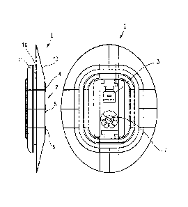
Figure 1: A fitting with inserted electrode in a top view and side view;
Figure 2: a perspectivist representation of the electrode in a top view from
above and
below.
Figure 3: A fitting without electrode from the internal side of the shaft;
Figure 4: the back side of the fitting pursuant to figure 3;
Figure 5: An internal shaft with inserted electrode, as well as
Figure 6: a partially cut away external shaft with inserted internal shaft.
Detailed Description of the Drawings
In figure 1, fitting 1 is shown with electrode 2 inserted, the electrical
connections 3
for conduction of the action potentials of the muscle groups via the skin
contacts 4, 5,
and 6. In the left side view, the spherical cap construction of the stump side
surface 13,
the fitting 1, the groove 10 and the retention bar are seen. In the groove,
10, the

= CA 02584954 2014-03-06
4
internal shaft is inserted. Through the pressing of the electrode fitting from
inside to
outside in a recess in the internal shaft that is so large that the contour is
assumed
within the groove 10, and is covered by the internal side of the fitting 1 and
the
retention bar 11, an air and watertight seal is created within the internal
shaft. A rotary
switch 7 on the back side of the electrode enables an adjustment of the
mounted
electrode 2.
The electrode 2 can be injected, adhered, pressed or form-fit into the
fitting. In the
perspectivist view in figure 2, one can see the finished mounted electrode 2
in fitting 1.
With a multiple component design of electrode and fitting, the fitting 1, as
shown in
figures 3 or 4 in various views, is made of a molded part or injection molded
part of a
skin tolerable material, silicon for example and is equipped with a recess 12
for the
insertion of the conduction electrode 2.
In figure five, the internal shaft 30 is represented diagonally from the back,
from the
insertion direction of the stump, an arm stump, in the example. The internal
shaft 30 is
constructed as a suction shaft and displays an electrode 2 on the internal
side which is
attached to the internal shaft 30 via a spherical cap fitting. The contour of
the fitting 1
on the internal side of shaft 30 is only slightly convex, in order to provide
the most
comfortable feeling for the wearer without pressure points while providing a
secure
connection to electrode 2 on the stump, so that there is a durative electro-
myographic
signal. As described above, the fitting 1 is equipped with groove 10, which
the internal
shaft grabs, so that the required recess is sealed against air and moisture.
In figure 6, we have a prosthesis part with an internal shaft 30, and an
external shaft 40,
whereby the external shaft is shown in a partial cutaway representation. The
internal
shaft 30 is secured via screws 34 to the stabile exterior shaft 40. In
addition, a bore
hole 32 is provided in the external shaft, through which the electrode 2,
which is
attached to internal shaft 30, can be adjusted by rotational switch 7.

=
CA 02584954 2014-03-06
In the partial cutaway representation we see that the internal shaft 30 is
attached to the
external shaft via a connection tube 50. The connection tube 50 enables an
escape of
the air in the internal shaft to an appropriate location in the externals
shaft. In order to
prevent back flow of the air, there is a unidirectional valve located in the
connection
5 tube 50. Through use of a lever 15, an o-ring 16 is activated within
the connection
tube 50 and thereby seals off the internal shaft 30. Air can then only escape
through he
unidirectional valve.

Representative Drawing
A single figure which represents the drawing illustrating the invention.
Administrative Status

2024-08-01:As part of the Next Generation Patents (NGP) transition, the Canadian Patents Database (CPD) now contains a more detailed Event History, which replicates the Event Log of our new back-office solution.

Please note that "Inactive:" events refers to events no longer in use in our new back-office solution.

For a clearer understanding of the status of the application/patent presented on this page, the site Disclaimer , as well as the definitions for Patent , Event History , Maintenance Fee  and Payment History  should be consulted.

Event History

Description Date
Letter Sent 2024-04-16
Inactive: COVID 19 - Deadline extended 2020-03-29
Common Representative Appointed 2019-10-30
Change of Address or Method of Correspondence Request Received 2018-01-09
Inactive: Late MF processed 2016-05-03
Letter Sent 2016-04-18
Grant by Issuance 2015-02-24
Inactive: Cover page published 2015-02-23
Pre-grant 2014-12-10
Inactive: Final fee received 2014-12-10
Notice of Allowance is Issued 2014-10-23
Letter Sent 2014-10-23
Notice of Allowance is Issued 2014-10-23
Inactive: Q2 passed 2014-10-02
Inactive: Approved for allowance (AFA) 2014-10-02
Amendment Received - Voluntary Amendment 2014-09-02
Inactive: S.30(2) Rules - Examiner requisition 2014-05-12
Inactive: Report - No QC 2014-04-29
Amendment Received - Voluntary Amendment 2014-03-06
Inactive: S.30(2) Rules - Examiner requisition 2013-11-15
Inactive: Report - No QC 2013-11-08
Letter Sent 2012-04-10
Request for Examination Requirements Determined Compliant 2012-03-22
All Requirements for Examination Determined Compliant 2012-03-22
Request for Examination Received 2012-03-22
Amendment Received - Voluntary Amendment 2012-03-22
Inactive: Filing certificate - No RFE (English) 2008-01-24
Application Published (Open to Public Inspection) 2007-11-09
Inactive: Cover page published 2007-11-09
Letter Sent 2007-10-29
Inactive: IPC assigned 2007-10-11
Inactive: First IPC assigned 2007-10-11
Inactive: Office letter 2007-09-18
Amendment Received - Voluntary Amendment 2007-09-12
Inactive: Single transfer 2007-09-12
Request for Priority Received 2007-09-11
Inactive: Correspondence - Formalities 2007-07-19
Request for Priority Received 2007-06-05
Inactive: Courtesy letter - Evidence 2007-05-15
Inactive: Filing certificate - No RFE (English) 2007-05-12
Filing Requirements Determined Compliant 2007-05-12
Application Received - Regular National 2007-05-12

Abandonment History

There is no abandonment history.

Maintenance Fee

The last payment was received on 2014-03-25

Note : If the full payment has not been received on or before the date indicated, a further fee may be required which may be one of the following

  • the reinstatement fee;
  • the late payment fee; or
  • additional fee to reverse deemed expiry.

Please refer to the CIPO Patent Fees web page to see all current fee amounts.

Owners on Record

Note: Records showing the ownership history in alphabetical order.

Current Owners on Record
OTTO BOCK HEALTHCARE PRODUCTS GMBH
Past Owners on Record
CHRISTIAN KLEIN
Past Owners that do not appear in the "Owners on Record" listing will appear in other documentation within the application.
Documents

To view selected files, please enter reCAPTCHA code :


To view images, click a link in the Document Description column. To download the documents, select one or more checkboxes in the first column and then click the "Download Selected in PDF format (Zip Archive)" or the "Download Selected as Single PDF" button.

List of published and non-published patent-specific documents on the CPD .

If you have any difficulty accessing content, you can call the Client Service Centre at 1-866-997-1936 or send them an e-mail at CIPO Client Service Centre.


Document
Description 
Date
(yyyy-mm-dd) 
Number of pages   Size of Image (KB) 
Abstract 2007-04-16 1 10
Description 2007-04-16 5 206
Claims 2007-04-16 2 48
Drawings 2007-04-16 6 238
Representative drawing 2007-10-29 1 13
Cover Page 2007-10-29 1 37
Drawings 2007-09-12 6 74
Description 2014-03-06 5 198
Claims 2014-03-06 2 38
Drawings 2014-03-06 6 74
Claims 2014-09-02 3 100
Cover Page 2015-02-04 1 33
Representative drawing 2015-02-04 1 8
Commissioner's Notice - Maintenance Fee for a Patent Not Paid 2024-05-28 1 569
Filing Certificate (English) 2007-05-12 1 158
Filing Certificate (English) 2008-01-24 1 160
Courtesy - Certificate of registration (related document(s)) 2007-10-29 1 104
Reminder of maintenance fee due 2008-12-17 1 112
Reminder - Request for Examination 2011-12-19 1 118
Acknowledgement of Request for Examination 2012-04-10 1 177
Commissioner's Notice - Application Found Allowable 2014-10-23 1 162
Late Payment Acknowledgement 2016-05-03 1 163
Maintenance Fee Notice 2016-05-03 1 170
Late Payment Acknowledgement 2016-05-03 1 163
Correspondence 2007-05-12 1 26
Correspondence 2007-06-05 4 93
Correspondence 2007-07-19 1 40
Correspondence 2007-09-11 1 11
Correspondence 2007-09-11 4 88
Correspondence 2014-12-10 1 36