Language selection

Search

Patent 2585258 Summary

Third-party information liability

Some of the information on this Web page has been provided by external sources. The Government of Canada is not responsible for the accuracy, reliability or currency of the information supplied by external sources. Users wishing to rely upon this information should consult directly with the source of the information. Content provided by external sources is not subject to official languages, privacy and accessibility requirements.

Claims and Abstract availability

Any discrepancies in the text and image of the Claims and Abstract are due to differing posting times. Text of the Claims and Abstract are posted:

  • At the time the application is open to public inspection;
  • At the time of issue of the patent (grant).
(12) Patent Application: (11) CA 2585258
(54) English Title: VACUUM CLEANER WITH AUTO SPRAY DEVICE
(54) French Title: ASPIRATEUR AVEC PULVERISATEUR AUTOMATIQUE
Status: Deemed Abandoned and Beyond the Period of Reinstatement - Pending Response to Notice of Disregarded Communication
Bibliographic Data
Abstracts

English Abstract


A vacuum cleaner with auto spray device comprising a body, a suction pipe, a
suction nozzle, an auto spray device and an aerosol can, the aerosol can is
positioned on the bottom of the auto spray device, wherein said auto spray
device is
fixed on the suction pipe. The auto spray device comprising a gear assembly, a
motor
an auto timing control circuit, and a power supply. The auto spray device is
extended
with a switch, wherein said switch is fixed on the suction pipe. The aerosol
can
comprising a spay nozzle, an aerosol valve and a can body. The gear assembly
comprising two gears and an driving gear, wherein said driving gear is
positioned on
the top of the spray nozzle of the aerosol can. The auto spray device is fixed
on the
suction pipe by the stud; and the auto spray device can rotate along the stud
at
various angles. Said suction pipe and the vacuum cleaner body is an integrity,
said
auto spray device is fixed on the vacuum cleaner body.


Claims

Note: Claims are shown in the official language in which they were submitted.

Claims
1. A vacuum cleaner with auto spray device, comprising: a body, a suction
pipe, a suction nozzle, an auto spray device and an aerosol can,
characterized in that: the aerosol can is positioned on the bottom of the
auto spray device, wherein said auto spray device is fixed on the suction
pipe.
2. A vacuum cleaner with auto spray device in accordance with claim 1,
characterized in that: the auto spray device comprising a gear assembly, a
motor, an auto timing control circuit, and a power supply.
3. A vacuum cleaner with auto spray device in accordance with claim 1,
characterized in that: the auto spray device is extended with a switch,
wherein said switch is fixed on the suction pipe.
4. A vacuum cleaner with auto spray device in accordance with claim 1,
characterized in that: the liquid in the aerosol can is water or disinfecting
solution or insect killer solution.
51. A vacuum cleaner with auto spray device in accordance with claim 1,
characterized in that: the aerosol can comprising a spay nozzle, an
aerosol valve and a can body.
6. A vacuum cleaner with auto spray device in accordance with claim 2,
characterized in that: the gear assembly comprising two gears and an
driving gear, wherein said driving gear is positioned on the top of the
spray nozzle of the aerosol can.
7. A vacuum cleaner with auto spray device in accordance with claim 1,
characterized in that: the auto spray device is fixed on the suction pipe
by the stud; and the auto spray device can rotate along the stud at various
angles.
8. A vacuum cleaner with auto spray device in accordance with claim 1,
characterized in that: said suction pipe and the vacuum cleaner body is an
integrity, said auto spray device is fixed on the vacuum cleaner body.
1

Description

Note: Descriptions are shown in the official language in which they were submitted.


CA 02585258 2007-04-02
DESCRIPTION
TITLE OF THE INVENTION
Vacuum cleaner with auto spray device
FIELD OF THE INVENTION
This invention relates the vacuum cleaner, further relates one kind to vacuum
and auto spray integrative vacuum cleaner.
BACKGROUND OF THE INVENTION
At present, most general vacuum cleaner only have vacuum function, but some
vacuum cleaner have sterilizing devices. Said sterilizing devices as Ozonizer
or
Ultraviolet radiation generator. Such as China Patent "Ultraviolet radiation
sterilizing
vacuum cleaner"(Patent number: 92239349) and "A purgation air cleaner" (Patent
number: 02225737), US Patent "Air cleaner, air cleaning method, and air
cleaner with
sterilization"(Patent number: 6,494,934).
The shortcomings of above patents are only have an effect to be vacuumed
object. To the ground or the environment that does not have an effect.
Otherwise,
above patent product is helpless when be requested to spray water or to kill
the
insect.
The purpose of the present invention is to solve the disadvantages
of vacuum cleaner, and provide people an integrated vacuum cleaner combined
with
functions of automatic spraying and vacuum cleaner. This device can work
automatically for timing spray, or be operated manually. Spraying of medicinal
liquid
is able to implement disinfection or kill insects, while spraying of water is
able to
settle down dusts and avoid static-electricity. Such elimination of static-
electricity
enables objects to be drafted into the machine more easily.
The beneficial effects of the present innovation are:
1. Feature a function of automatic spraying of water, disinfecting solution
and
insect killer solution etc;
2. Be controlled automatically or manually through a convenient and easy
operation;
Enable disinfection for outside and inside environments of a vacuum
2

CA 02585258 2007-04-02
1. cleaner;
2. Water spraying is able to eliminate static electricity to achieve better
vacuum cleaning effect.
SUMMARY OF THE INVENTION
This and other advantages are provided by a vacuum cleaner with auto spray
device comprising a body, a suction pipe, a suction nozzle, an auto spray
device and
an aerosol can, the aerosol can is positioned on the bottom of the auto spray
device,
wherein said auto spray device is fixed on the suction pipe.
The auto spray device comprising a gear assembly, a motor, an auto timing
control circuit, and a power supply. The auto spray device is extended with a
switch,
wherein said switch is fixed on the suction pipe. The aerosol can comprising a
spay
nozzle, an aerosol valve and a can body. The gear assembly comprising two
gears
and an driving gear, wherein said driving gear is positioned on the top of the
spray
nozzle of the aerosol can. The auto spray device is fixed on the suction pipe
by the
stud; and the auto spray device can rotate along the stud at various angles.
Said
suction pipe and the vacuum cleaner body is an integrity, said auto spray
device is
fixed on the vacuum cleaner body.
BRIEF DESCRIPTION OF THE DRAWINGS
Better understanding of the present invention will be had when reference is
made to
the accompanying drawings, wherein identical parts are identified by identical
reference numerals and wherein:
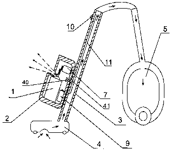
FIG. 1 is a side view of construction for the present innovation according to
the
preferred embodiment;
FIG 2, is a frontal section view of the auto spray device of the present
innovation;
FIG. 3, is a schematic drawing of a spray device of the present innovation
fixed on a
vacuum cleaner integrated with a suction pipe and a body.
DETAILED DESCRIPTION OF THE INVENTION
Figure 1 and 2 hereto shows the preferred embodiment of the present
innovation. An
aerosol can I is able to be filled with water, disinfection solution or insect
killer
2

CA 02585258 2007-04-02
solution along with compressed air. Referring to Figure 2, an auto spray
device 2
comprises a gear assembly 6, a motor 7, an auto timing control circuit 8 and a
power
supply 9, wherein said gear assembly 6 comprises two gears 30,31 and a driving
gear
32. The power supply 9 is electrically connected with the auto timing control
circuit 8,
which has an electrical connection with the motor 7. The shaft of the motor 7
is
attached with the gear 30. The gear 30 is engaged with the gear 31, and the
gear 31 is
engaged with driving gear 32, which is positioned on the top of a spray head
20 of the
aerosol can. When a signal is sent from the auto timing control circuit 8 or a
switch 10,
the motor 7 rotates to move the gear 31 through triggering movements of the
gear 30,
and consequently start movements of the driving gear 32, in order to press
down the
spray head 20 of the aerosol can, and finally enable the aerosol can I to
spray. When
spraying motion is done, an aerosol valve 21 can rebound to reposition the
driving
gear 32 trough triggering the spray head 20. Thus the entire spray operation
is
completed. The auto spray device 2 is able to rotate around a suction pipe 3
to enable
a multi-orientation spray in front and rear, right and left directions.
Referring to Figure
3, the auto spray device 2 can be fixed on a suction head 4 or a vertical
vacuum
cleaner 50. Moreover, the auto spray device 2 is able to make a muiti-angie
rotation
around a stud 40 for purposes of diversified environments.
The auto spray device 2 is able to work in a mode of timing repetition for
operation, and enables a timing spray of water or medicinal liquid during
vacuum
cleaning made by users. Water, disinfection solution or insect killer solution
can be
used as the liquid In the aerosol can. Users can also actuate the switch 10 to
control
the aerosol can for a spray of disinfection liquid, and enable disinfection of
the
environment, as well as of objects in the dust collector of the vacuum
cleaner, into
which the disinfection solution is drafted.
For the present innovation, a pressure container should be adopted for the
aerosol can to ensure the effect of atomization; otherwise, there is a
difficulty in
achieving anticipated purposes. Besides the construction shown in Figure 1, 2
and 3,
the vacuum cleaner in the present Innovation may feature other construction
conversions. Such simple conversions shall not exceed the protection scope of
the
present Innovation.
3

Representative Drawing
A single figure which represents the drawing illustrating the invention.
Administrative Status

2024-08-01:As part of the Next Generation Patents (NGP) transition, the Canadian Patents Database (CPD) now contains a more detailed Event History, which replicates the Event Log of our new back-office solution.

Please note that "Inactive:" events refers to events no longer in use in our new back-office solution.

For a clearer understanding of the status of the application/patent presented on this page, the site Disclaimer , as well as the definitions for Patent , Event History , Maintenance Fee  and Payment History  should be consulted.

Event History

Description Date
Application Not Reinstated by Deadline 2010-04-06
Time Limit for Reversal Expired 2010-04-06
Inactive: Adhoc Request Documented 2010-01-07
Deemed Abandoned - Failure to Respond to Maintenance Fee Notice 2009-04-02
Application Published (Open to Public Inspection) 2008-10-02
Inactive: Cover page published 2008-10-01
Inactive: IPC assigned 2008-09-11
Inactive: IPC assigned 2008-09-09
Inactive: First IPC assigned 2008-09-09
Inactive: IPC assigned 2008-09-09
Application Received - Regular National 2007-05-15
Filing Requirements Determined Compliant 2007-05-15
Inactive: Filing certificate - No RFE (English) 2007-05-15

Abandonment History

Abandonment Date Reason Reinstatement Date
2009-04-02

Fee History

Fee Type Anniversary Year Due Date Paid Date
Application fee - small 2007-04-02
Owners on Record

Note: Records showing the ownership history in alphabetical order.

Current Owners on Record
ZHI XIONG HUO
Past Owners on Record
None
Past Owners that do not appear in the "Owners on Record" listing will appear in other documentation within the application.
Documents

To view selected files, please enter reCAPTCHA code :


To view images, click a link in the Document Description column. To download the documents, select one or more checkboxes in the first column and then click the "Download Selected in PDF format (Zip Archive)" or the "Download Selected as Single PDF" button.

List of published and non-published patent-specific documents on the CPD .

If you have any difficulty accessing content, you can call the Client Service Centre at 1-866-997-1936 or send them an e-mail at CIPO Client Service Centre.


Document
Description 
Date
(yyyy-mm-dd) 
Number of pages   Size of Image (KB) 
Abstract 2007-04-02 1 19
Description 2007-04-02 3 116
Claims 2007-04-02 1 33
Drawings 2007-04-02 3 28
Representative drawing 2008-09-05 1 10
Cover Page 2008-09-17 2 46
Filing Certificate (English) 2007-05-15 1 158
Notice: Maintenance Fee Reminder 2009-01-05 1 121
Courtesy - Abandonment Letter (Maintenance Fee) 2009-05-28 1 172
Second Notice: Maintenance Fee Reminder 2009-10-05 1 118
Notice: Maintenance Fee Reminder 2010-01-05 1 128
Correspondence 2007-05-15 1 10