Language selection

Search

Patent 2585516 Summary

Third-party information liability

Some of the information on this Web page has been provided by external sources. The Government of Canada is not responsible for the accuracy, reliability or currency of the information supplied by external sources. Users wishing to rely upon this information should consult directly with the source of the information. Content provided by external sources is not subject to official languages, privacy and accessibility requirements.

Claims and Abstract availability

Any discrepancies in the text and image of the Claims and Abstract are due to differing posting times. Text of the Claims and Abstract are posted:

  • At the time the application is open to public inspection;
  • At the time of issue of the patent (grant).
(12) Patent Application: (11) CA 2585516
(54) English Title: NORMALIZED LEAST MEAN SQUARE CHIP-LEVEL EQUALIZATION ADVANCED DIVERSITY RECEIVER
(54) French Title: RECEPTEUR EN DIVERSITE AMELIORE A EGALISATION AU NIVEAU PUCE PAR MOINDRES CARRES MOYENS NORMALISES
Status: Deemed Abandoned and Beyond the Period of Reinstatement - Pending Response to Notice of Disregarded Communication
Bibliographic Data
(51) International Patent Classification (IPC):
  • H03H 07/30 (2006.01)
  • H03H 07/40 (2006.01)
  • H03K 05/159 (2006.01)
(72) Inventors :
  • ZEIRA, ARIELA (United States of America)
  • PIETRASKI, PHILIP J. (United States of America)
  • PAN, KYLE JUNG-LIN (United States of America)
  • BELURI, MIHAELA C. (United States of America)
  • YANG, RUI (United States of America)
(73) Owners :
  • INTERDIGITAL TECHNOLOGY CORPORATION
(71) Applicants :
  • INTERDIGITAL TECHNOLOGY CORPORATION (United States of America)
(74) Agent: SMART & BIGGAR LP
(74) Associate agent:
(45) Issued:
(86) PCT Filing Date: 2005-10-18
(87) Open to Public Inspection: 2006-05-18
Examination requested: 2007-04-26
Availability of licence: N/A
Dedicated to the Public: N/A
(25) Language of filing: English

Patent Cooperation Treaty (PCT): Yes
(86) PCT Filing Number: PCT/US2005/037656
(87) International Publication Number: US2005037656
(85) National Entry: 2007-04-26

(30) Application Priority Data:
Application No. Country/Territory Date
11/210,949 (United States of America) 2005-08-24
60/625,648 (United States of America) 2004-11-05

Abstracts

English Abstract


A receiver which includes at least one equalizer filter and a tap coefficients
generator for implementing receive diversity. The equalizer filter processes a
signal derived from signals received by a plurality of antennas. In one
embodiment, sample data streams from the antennas are merged into one sample
data stream. The merged sample data stream is processed by a single extended
equalizer filter, whereby filter coefficients are adjusted in accordance with
a joint error signal. A filter coefficient correction term used by the
equalizer filter is generated by the tap coefficients generator using a
normalized least mean square (NLMS) algorithm. In another embodiment, a
plurality of equalizer filters are utilized, whereby each equalizer receives a
sample data stream from a specific one of the antennas. In yet another
embodiment, the sample data streams are combined after being processed by a
plurality of matched filters based on respective estimated channel impulse
responses.


French Abstract

L'invention concerne un récepteur comprenant au moins un filtre égaliseur et un générateur de coefficients de filtre permettant la mise en oeuvre d'une diversité de réception. Ce filtre égaliseur traite un signal dérivé des signaux reçus par une pluralité d'antennes. Dans une forme de réalisation, des flux de données-échantillon provenant des antennes sont fusionnés en un seul flux de données-échantillon. Le flux de données-échantillon fusionné est traité par un seul filtre égaliseur étendu, les coefficients de filtre étant définis conformément à un signal d'erreur commun. Un terme de correction du coefficient de filtre utilisé par le filtre égaliseur est généré par le générateur de coefficients de filtre au moyen d'un algorithme des moindres carrés moyens normalisés (NLMS). Dans une seconde forme de réalisation, une pluralité de filtres égaliseurs sont utilisés, chaque égaliseur recevant un flux de données-échantillon à partir d'une antenne spécifique. Dans une troisième forme de réalisation, les flux de données-échantillon sont combinés après avoir été traités par une pluralité de filtres accordés, en fonction des réponses impulsionnelles des voies estimées respectives.

Claims

Note: Claims are shown in the official language in which they were submitted.


CLAIMS
What is claimed is:
1. A receiver comprising:
a plurality of antennas for receiving signals;
a plurality of samplers coupled to respective ones of the antennas for
generating a plurality of sample data streams, wherein each of the samplers
generates a respective sample data stream based on the signals received by a
respective one of the antennas;
a multiplexer for merging the sample data streams generated by the
samplers into one merged sample data stream; and
an equalizer for processing the merged sample data stream.
2. The receiver of claim 1 wherein the receiver is a code division
multiple access (CDMA) receiver in which the sample data streams are sampled
at two times a chip rate by the respective samplers, and the merged sample
data
stream is processed by the equalizer at four times the chip rate.
3. The receiver of claim 1 wherein the equalizer comprises:
an equalizer filter for processing the merged sample stream with filter
coefficients; and
a tap coefficients generator for generating at least one filter coefficient
correction term for use by the equalizer filter.
4. The receiver of claim 3 wherein the filter coefficient correction term
is generated based on a despread pilot sequence.
5. The receiver of claim 3 wherein the filter coefficient correction term
is generated based on a non-despread pilot sequence.
-16-

6. The receiver of claim 3 wherein the filter coefficient correction term
is generated by the tap coefficients generator using a normalized least mean
square (NLMS) algorithm.
7. The receiver of claim 3 wherein the tap coefficients generator
comprises:
a first multiplier coupled to a first output of the equalizer filter, the
first
multiplier being configured to receive an equalizer output signal from the
first
output of the equalizer filter and multiply the equalizer output signal with a
scrambling code conjugate signal to generate a descrambled equalizer output
signal;
a second multiplier coupled to a second output of the equalizer filter, the
second multiplier being configured to receive an equalizer tapped delay line
(TDL) signal from the second output of the equalizer filter and multiply the
equalizer TDL signal with the scrambling code conjugate signal to generate a
vector signal having a value X;
an adder for subtracting the first descrambled signal from a pilot reference
signal to generate an error signal;
a vector norm square estimator for receiving the vector signal and
generating a signal having a value which is equal to .parallel. X .parallel.2;
and
a taps correction unit which generates a vector signal representing tap
values used by the equalizer filter to generate the equalizer output signal
and the
equalizer TDL signal.
8. A receiver comprising:
a plurality of antennas for receiving signals;
a plurality of samplers coupled to respective ones of the antennas for
generating a plurality of sample data streams, wherein each of the samplers
generates a respective sample data stream based on the signals received by a
respective one of the antennas; and
an equalizer for processing the sample data streams.
-17-

9. The receiver of claim 8 wherein the receiver is a code division
multiple access (CDMA) receiver in which the sample data streams are sampled
at two times a chip rate by the respective samplers.
10. The receiver of claim 8 wherein the equalizer comprises:
a plurality of equalizer filters coupled to respective ones of the samplers
for
processing the sample data streams using filter coefficients; and
a tap coefficients generator for generating at least one filter coefficient
correction term for use by the equalizer filters.
11. The receiver of claim 10 wherein the receiver is a code division
multiple access (CDMA) receiver in which the sample data streams are sampled
at two times a chip rate by the respective samplers and are down-sampled to
chip
rate by the respective equalizer filters.
12. The receiver of claim 10 wherein the filter coefficient correction term
is generated based on a despread pilot sequence.
13. The receiver of claim 10 wherein the filter coefficient correction term
is generated based on a non-despread pilot sequence.
14. The receiver of claim 10 wherein the filter coefficient correction term
is generated by the tap coefficients generator using a normalized least mean
square (NLMS) algorithm.
15. The receiver of claim 10 wherein the tap coefficients generator
comprises:
a plurality of serial-to-parallel (S4P) to vector converters coupled to
respective ones of the samplers and equalizer filters for converting each
respective sample data stream to a length L vectors signal;
-18-

a plurality of vector descrambling multipliers coupled to respective ones of
the S.fwdarw.P to vector converters, each vector descrambling multiplier being
configured to multiply the length L vectors signal output by a respective
S.fwdarw.P to
vector converter with a scrambling code conjugate signal to generate a
descrambled vectors signal;
a first adder coupled to each of the equalizer filters for adding an equalized
output signal generated by each of the equalizer filters to generate a summed
equalizer output signal;
an equalizer output multiplier coupled to the adder for multiplying the
summed equalizer output signal with the scrambling code conjugate signal to
generate a descrambled summed equalizer signal;
a second adder for subtracting the descrambled summed equalizer signal
from a pilot reference signal to generate a joint error signal; and
a plurality of correction term generators coupled to the adder, a respective
one of the vector descrambling multipliers and a respective one of the
equalizer
filters, wherein each of the correction term generators outputs correction
terms
for use by a respective one of the equalizer filters based on the joint error
signal
and a respective descrambled vectors signal generated by a respective vector
descrambling multiplier.
16. The receiver of claim 15 wherein the tap coefficients generator
further comprises:
a plurality of vectors accumulators coupled between respective ones of the
vector descrambling multipliers and respective ones of the correction term
generators; and
a chips accumulator coupled between the equalizer output multiplier and
the second adder.
17. A receiver comprising:
a plurality of antennas for receiving signals;
-19-

a plurality of samplers coupled to respective ones of the antennas for
generating a plurality of sample data streams, wherein each of the samplers
generates a respective sample data stream based on the signals received by a
respective one of the antennas;
a plurality of channel estimators for estimating a channel impulse
response;
a plurality of matched filters (MFs) coupled to respective ones of the
samplers and the MFs for processing the sample data streams in accordance with
the estimated channel impulse response;
a combiner for combining outputs from the MFs; and
an equalizer for processing the combined outputs of the MFs.
18. The receiver of claim 17 wherein the receiver is a code division
multiple access (CDMA) receiver in which the sample data streams are sampled
at two times a chip rate by the respective samplers.
19. The receiver of claim 17 wherein the combiner combines a plurality
of multipath components of the signals received by the antennas.
20. The receiver of claim 17 wherein the equalizer comprises:
an equalizer filter for processing the combined outputs of the MFs using
filter coefficients; and
a tap coefficients generator for generating at least one filter coefficient
correction term for use by the equalizer filter.
21. The receiver of claim 17 wherein the receiver is a code division
multiple access (CDMA) receiver in which the sample data streams are sampled
at two times a chip rate by the respective samplers and are down-sampled to
chip
rate by the equalizer filter.
-20-

22. The receiver of claim 20 wherein the filter coefficient correction term
is generated based on a despread pilot sequence.
23. The receiver of claim 20 wherein the filter coefficient correction term
is generated based on a non-despread pilot sequence.
24. The receiver of claim 15 wherein the filter coefficient correction term
is generated by the tap coefficients generator using a normalized least mean
square (NLMS) algorithm.
25. The receiver of claim 20 wherein the tap coefficients generator
comprises:
a serial-to-parallel (S.fwdarw.P) to vector converter coupled to the combiner
and
the equalizer filter for converting the combined outputs of the MFs to a
length L
vectors signal;
a vector descrambling multiplier coupled to the S.fwdarw.P to vector converter
for multiplying the length L vectors signal output by the S.fwdarw.P to vector
converter
with a scrambling code conjugate signal to generate a descrambled vectors
signal;
an equalizer output multiplier coupled to the equalizer filter for
multiplying an equalizer output signal generated by the equalizer filter with
a
scrambling code conjugate signal to generate a descrambled equalizer signal;
an adder for subtracting the descrambled equalizer signal from a pilot
reference signal to generate an error signal; and
a correction term generator coupled to the adder, the vector descrambling
multiplier and the equalizer filters, wherein the correction term generator
outputs correction terms for use by the equalizer filter based on the error
signal
and the descrambled vectors signal generated by the vector descrambling
multiplier.
26. The receiver of claim 25 wherein the tap coefficients generator
further comprises:
-21-

a vectors accumulator coupled between the vector descrambling multiplier
and the correction term generator; and
a chips accumulator coupled between the equalizer output multiplier and
the adder.
27. An integrated circuit (IC) used in conjunction with a receiver having
a plurality of antennas for receiving signals, the IC comprising:
a plurality of samplers coupled to respective ones of the antennas for
generating a plurality of sample data streams, wherein each of the samplers
generates a respective sample data stream based on the signals received by a
respective one of the antennas;
a multiplexer for merging the sample data streams generated by the
samplers into one merged sample data stream; and
an equalizer for processing the merged sample data stream.
28 The IC of claim 27 wherein the receiver is a code division multiple
access (CDMA) receiver, the sample data streams are sampled at two times a
chip rate by the respective samplers, and the merged sample data stream is
processed by the equalizer at four times the chip rate.
29. The IC of claim 27 wherein the equalizer comprises:
an equalizer filter for processing the merged sample stream with filter
coefficients; and
a tap coefficients generator for generating at least one filter coefficient
correction term for use by the equalizer filter.
30. The IC of claim 29 wherein the filter coefficient correction term is
generated based on a despread pilot sequence.
31. The IC of claim 29 wherein the filter coefficient correction term is
generated based on a non-despread pilot sequence.
-22-

32. The IC of claim 29 wherein the filter coefficient correction term is
generated by the tap coefficients generator using a normalized least mean
square
(NLMS) algorithm.
33. The IC of claim 29 wherein the tap coefficients generator comprises:
a first multiplier coupled to a first output of the equalizer filter, the
first
multiplier being configured to receive an equalizer output signal from the
first
output of the equalizer filter and multiply the equalizer output signal with a
scrambling code conjugate signal to generate a descrambled equalizer output
signal;
a second multiplier coupled to a second output of the equalizer filter, the
second multiplier being configured to receive an equalizer tapped delay line
(TDL) signal from the second output of the equalizer filter and multiply the
equalizer TDL signal with the scrambling code conjugate signal to generate a
vector signal having a value X;
an adder for subtracting the first descrambled signal from a pilot reference
signal to generate an error signal;
a vector norm square estimator for receiving the vector signal and
generating a signal having a value which is equal to ~×~2; and
a taps correction unit which generates a vector signal representing tap
values used by the equalizer filter to generate the equalizer output signal
and the
equalizer TDL signal.
34. An integrated circuit (IC) used in conjunction with a receiver having
a plurality of antennas for receiving signals, the IC comprising:
a plurality of samplers coupled to respective ones of the antennas for
generating a plurality of sample data streams, wherein each of the samplers
generates a respective sample data stream based on the signals received by a
respective one of the antennas; and
an equalizer for processing the sample data streams.
-23-

35. The IC of claim 34 wherein the receiver is a code division multiple
access (CDMA) receiver and the sample data streams are sampled at two times a
chip rate by the respective samplers.
36. The IC of claim 34 wherein the equalizer comprises:
a plurality of equalizer filters coupled to respective ones of the samplers
for
processing the sample data streams using filter coefficients; and
a tap coefficients generator for generating at least one filter coefficient
correction term for use by the equalizer filters.
37. The IC of claim 36 wherein the receiver is a code division multiple
access (CDMA) receiver and the sample data streams are sampled at two times a
chip rate by the respective samplers and are down-sampled to chip rate by the
respective equalizer filters.
38. The IC of claim 36 wherein the filter coefficient correction term is
generated based on a despread pilot sequence.
39. The IC of claim 36 wherein the filter coefficient correction term is
generated based on a non-despread pilot sequence.
40. The IC of claim 36 wherein the filter coefficient correction term is
generated by the tap coefficients generator using a normalized least mean
square
(NLMS) algorithm.
41. The IC of claim 36 wherein the tap coefficients generator comprises:
a plurality of serial-to-parallel (S.fwdarw.P) to vector converters coupled to
respective ones of the samplers and equalizer filters for converting each
respective sample data stream to a length L vectors signal;
-24-

a plurality of vector descrambling multipliers coupled to respective ones of
the S.fwdarw.P to vector converters, each vector descrambling multiplier being
configured to multiply the length L vectors signal output by a respective
S.fwdarw.P to
vector converter with a scrambling code conjugate signal to generate a
descrambled vectors signal;
a first adder coupled to each of the equalizer filters for adding an equalized
output signal generated by each of the equalizer filters to generate a summed
equalizer output signal;
an equalizer output multiplier coupled to the adder for multiplying the
summed equalizer output signal with the scrambling code conjugate signal to
generate a descrambled summed equalizer signal;
a second adder for subtracting the descrambled summed equalizer signal
from a pilot reference signal to generate a joint error signal; and
a plurality of correction term generators coupled to the adder, a respective
one of the vector descrambling multipliers and a respective one of the
equalizer
filters, wherein each of the correction term generators outputs correction
terms
for use by a respective one of the equalizer filters based on the joint error
signal
and a respective descrambled vectors signal generated by a respective vector
descrambling multiplier.
42. The IC of claim 41 wherein the tap coefficients generator further
comprises:
a plurality of vectors accumulators coupled between respective ones of the
vector descrambling multipliers and respective ones of the correction term
generators; and
a chips accumulator coupled between the equalizer output multiplier and
the second adder.
43. An integrated circuit (IC) used in conjunction with a receiver having
a plurality of antennas for receiving signals, the IC comprising:
-25-

a plurality of samplers coupled to respective ones of the antennas for
generating a plurality of sample data streams, wherein each of the samplers
generates a respective sample data stream based on the signals received by a
respective one of the antennas;
a plurality of channel estimators for estimating a channel impulse
response;
a plurality of matched filters (MFs) coupled to respective ones of the
samplers and the MFs for processing the sample data streams in accordance with
the estimated channel impulse response;
a combiner for combining outputs from the MFs; and
an equalizer for processing the combined outputs of the MFs.
44. The IC of claim 43 wherein the receiver is a code division multiple
access (CDMA) receiver and the sample data streams are sampled at two times a
chip rate by the respective samplers.
45. The IC of claim 43 wherein the combiner combines a plurality of
multipath components of the signals received by the antennas.
46. The IC of claim 43 wherein the equalizer comprises:
an equalizer filter for processing the combined outputs of the MFs using
filter coefficients; and
a tap coefficients generator for generating at least one filter coefficient
correction term for use by the equalizer filter.
47. The IC of claim 43 wherein the receiver is a code division multiple
access (CDMA) receiver in which the sample data streams are sampled at two
times a chip rate by the respective samplers and are down-sampled to chip rate
by the equalizer filter.
-26-

48. The IC of claim 46 wherein the filter coefficient correction term is
generated based on a despread pilot sequence.
49. The IC of claim 46 wherein the filter coefficient correction term is
generated based on a non-despread pilot sequence.
50. The IC of claim 46 wherein the filter coefficient correction term is
generated by the tap coefficients generator using a normalized least mean
square
(NLMS) algorithm.
51. The IC of claim 46 wherein the tap coefficients generator comprises:
a serial-to-parallel (S.fwdarw.P) to vector converter coupled to the combiner
and
the equalizer filter for converting the combined outputs of the MFs to a
length L
vectors signal;
a vector descrambling multiplier coupled to the S.fwdarw.P to vector converter
for multiplying the length L vectors signal output by the S.fwdarw.P to vector
converter
with a scrambling code conjugate signal to generate a descrambled vectors
signal;
an equalizer output multiplier coupled to the equalizer filter for
multiplying an equalizer output signal generated by the equalizer filter with
a
scrambling code conjugate signal to generate a descrambled equalizer signal;
an adder for subtracting the descrambled equalizer signal from a pilot
reference signal to generate an error signal; and
a correction term generator coupled to the adder, the vector descrambling
multiplier and the equalizer filters, wherein the correction term generator
outputs correction terms for use by the equalizer filter based on the error
signal
and the descrambled vectors signal generated by the vector descrambling
multiplier.
52. The IC of claim 51 wherein the tap coefficients generator further
comprises:
-27-

a vectors accumulator coupled between the vector descrambling multiplier
and the correction term generator; and
a chips accumulator coupled between the equalizer output multiplier and
the adder.
53. A method of processing signals received from a plurality of
antennas, the method comprising:
(a) generating a plurality of sample data streams, wherein each of sample
data stream is based on the, signals received by a respective one of the
antennas;
(b) merging the sample data streams into one merged sample data stream;
and
(c) processing the merged sample data stream.
54. The method of claim 53 wherein a code division multiple access
(CDMA) receiver is used to perform steps (a)-(c), the method further
comprising:
(d) sampling the sample data streams at two times a chip rate; and
(e) processing the merged sample data stream at four times the chip rate.
55. The method of claim 53 further comprising:
(d) processing the merged sample stream with filter coefficients; and
(e) generating at least one filter coefficient correction term.
56. The method of claim 55 wherein the filter coefficient correction term
is generated based on a despread pilot sequence.
57. The method of claim 55 wherein the filter coefficient correction term
is generated based on a non-despread pilot sequence.
58. The method of claim 55 wherein the filter coefficient correction term
is generated using a normalized least mean square (NLMS) algorithm.
-28-

59. The method of claim 55 further comprises:
(f) receiving an equalized output signal and multiplying the equalized
output signal with a scrambling code conjugate signal to generate a
descrambled
equalized output signal;
(g) receiving an equalizer tapped delay line (TDL) signal and multiplying
the equalizer TDL signal with the scrambling code conjugate signal to generate
a
vector signal having a value X;
(h) subtracting the first descrambled signal from a pilot reference signal to
generate an error signal;
(i) generating a signal having a value which is equal to ~ X ~2 based on the
vector signal; and
(j) generating a vector signal representing tap values used to generate the
equalized output signal and the equalizer TDL signal.
60. A method of processing signals received from a plurality of
antennas, the method comprising:
(a) generating a plurality of sample data streams, wherein each of sample
data stream is based on the signals received by a respective one of the
antennas;
and
(b) processing the sample data streams.
61. The method of claim 60 wherein a code division multiple access
(CDMA) receiver is used to perform steps (a) and (b), the method further
comprising:
(c) sampling the sample data streams at two times a chip rate.
62. The method of claim 60 further comprising:
(c) processing the sample data streams using filter coefficients; and
(d) generating at least one filter coefficient correction term.
-29-

63. The method of claim 60 wherein a code division multiple access
(CDMA) receiver is used to perform steps (a)-(d), the method further
comprising:
(e) sampling the sample data streams at two times a chip rate; and
(f) down-sampling the sample data streams to chip rate.
64. The method of claim 62 wherein the filter coefficient correction term
is generated based on a despread pilot sequence.
65. The method of claim 62 wherein the filter coefficient correction term
is generated based on a non-despread pilot sequence.
66. The method of claim 62 wherein the filter coefficient correction term
is generated using a normalized least mean square (NLMS) algorithm.
67. The method of claim 62 further comprising:
(e) converting each respective sample data stream to a length L vectors
signal;
(f) multiplying each length L vectors signal with a scrambling code
conjugate signal to generate a respective descrambled vectors signal;
(g) adding a plurality of equalized output signals to generate a summed
equalizer output signal;
(h) multiplying the summed equalizer output signal with the scrambling
code conjugate signal to generate a descrambled summed equalizer signal;
(i) subtracting the descrambled summed equalizer signal from a pilot
reference signal to generate a joint error signal; and
(j) generating correction terms based on the joint error signal and a
respective descrambled vectors signal.
68. A method of processing signals received from a plurality of
antennas, the method comprising:
-30-

(a) generating a plurality of sample data streams, wherein each of sample
data stream is based on the signals received by a respective one of the
antennas;
(b) estimating a channel impulse response;
(c) processing the sample data streams in accordance with the estimated
channel impulse response to generate a plurality of processed signals;
(d) combining the processed signals; and
(e) processing the combined processed signals.
69. The method of claim 68 wherein a code division multiple access
(CDMA) receiver is used to perform steps (a)-(e), the method further
comprising:
(f) sampling the sample data streams at two times a chip rate.
70. The method of claim 68 wherein step (d) comprises combining a
plurality of multipath components of the signals received by the antennas.
71. The method of claim 68 further comprising: -
(f) processing the combined processed signals using filter coefficients; and
(g) generating at least one filter coefficient correction term.
72. The method of claim 68 wherein a code division multiple access
(CDMA) receiver is used to perform steps (a)-(e), the method further
comprising:
(f) sampling the sample data streams at two times a chip rate; and
(g) down-sampling the sample data streams to chip rate.
73. The method of claim 71 wherein the filter coefficient correction term
is generated based on a despread pilot sequence.
74. The method of claim 71 wherein the filter coefficient correction term
is generated based on a non-despread pilot sequence.
-31-

75. The method of claim 71 wherein the filter coefficient correction term
is generated using a normalized least mean square (NLMS) algorithm.
76. The method of claim 71 further comprising:
(h) converting the combined processed signals to a length L vectors signal;
(i) multiplying the length L vectors signal output by the S.fwdarw.P to vector
converter with a scrambling code conjugate signal to generate a descrambled
vectors signal;
(j) multiplying an equalized output signal with a scrambling code
conjugate signal to generate a descrambled equalizer signal;
(k) subtracting the descrambled equalizer signal from a pilot reference
signal to generate an error signal; and
(l) generating correction terms based on the error signal and the
descrambled vectors signal.
-32-

Description

Note: Descriptions are shown in the official language in which they were submitted.


CA 02585516 2007-04-26
WO 2006/052407 PCT/US2005/037656
[0001] NORMALIZED LEAST MEAN SQUARE CHIP-LEVEL
EQUALIZATION ADVANCED DIVERSITY RECEIVER
[0002] FIELD OF THE INVENTION
[0003] The present invention is related to a wireless communication system
which employs receiver diversity. More particularly, the present invention
relates to receive diversity techniques for a normalized least mean square
(NLMS) chip-level equalization (CLE) receiver.
[00041 BACKGROUND
[0005] Chip-level equalizers are suitable candidates for advanced receiver
systems, such as those used in wireless transmit/receive units (WTRUs) and
base
stations. An NLMS-based CLE receiver offers superior performance for high data
rate services such as high speed downlink packet access (HSDPA) over a Rake
receiver. A typical NLMS receiver consists of an equalizer filter and an NLMS
algorithm. The equalizer filter is typically a finite impulse response (FIR)
filter.
[0006] The NLMS algorithm is used as the tap coefficients generator. It
generates appropriate tap coefficients used by the equalizer filter and
updates
them appropriately and iteratively in a timely manner. Typically, tap
coefficients generation includes the error signal computation, vector norm
calculation and leaky integration to generate and update the tap coefficients.
[0007] Although the NLMS CLE has been well proven for the single antenna
receiver, an extension of the NLMS algorithm for receiver diversity has not
been
provided. A simple extension would be to provide one NLMS CLE for each
antenna and combine the results of each. However, this is unnecessarily
suboptimal.
[00081 SUMMARY
[0009] The present invention is related to a receiver which includes at least
one equalizer filter and a tap coefficients generator for implementing receive
diversity. The equalizer filter processes a signal derived from signals
received by
a plurality of antennas. In one embodiment, sample data streams from the
-1-

CA 02585516 2007-04-26
WO 2006/052407 PCT/US2005/037656
antennas are merged into one sample data stream. The merged sample data
stream is processed by a single extended equalizer filter, whereby filter
coefficients are adjusted in accordance with a joint error signal. A filter
coefficient correction term used by the equalizer filter is generated by the
tap
coefficients generator using an NLMS algorithm. In another embodiment, a
plurality of equalizer filters is utilized, whereby each equalizer receives a
sample
data stream from a specific one of the antennas. In yet another embodiment,
the
sample data streams are combined after being processed by a plurality of
matched filters based on respective estimated channel impulse responses.
[0010] BRIEF DESCRIPTION OF THE DRAWINGS
[0011] A more detailed understanding of the invention may be had from the
following description, given by way of example and to be understood in
conjunction with the accompanying drawings wherein:
[0012] Figure 1 is a block diagram of an exemplary NLMS CLE receiver
configured in accordance with a first embodiment of the present invention;
[0013] Figure 2 is a block diagram of an exemplary NLMS CLE receiver
configured in accordance with a second embodiment of the present invention;
[0014] Figure 3 is a block diagram of a simplified version of the NLMS CLE
receiver of Figure 2; and
[0015] Figure 4 is a block diagram of an exemplary NLMS CLE receiver
configured in accordance with a third embodiment of the present invention.
[0016] DETAILED DESCRIPTION OF THE PREFERRED EMBODIMENTS
[0017] The preferred embodiments will be described with reference to the
drawing figures where like numerals represent like elements throughout.
[00181 Hereafter, the terminology "WTRU" includes but is not limited to a
user equipment (UE), a mobile station, a laptop, a personal data assistant
(PDA),
a fixed or mobile subscriber unit, a pager, or any other type of device
capable of
operating in a wireless environment. When referred to hereafter, the
terminology "base station" includes but is not limited to an access point
(AP), a
Node-B, a site controller or any other type of interfacing device in a
wireless
-2-

CA 02585516 2007-04-26
WO 2006/052407 PCT/US2005/037656
environment.
[0019] The features of the present invention may be incorporated into an
integrated circuit (IC) or be configured in a circuit comprising a multitude
of
interconnecting components.
[0020] Hereafter, the present invention will be explained with reference to
an NLMS algorithm. However, it should be noted that any other adaptive
equalization algorithm may be utilized.
[0021] Hereafter, the present invention will be explained with reference to
methods of receiver diversity for an NLMS algorithm. However, it should be
noted that any type of adaptive equalization or filtering, such as least mean
square (LMS), Griffith's algorithm, channel estimation based NLMS (CE-NLMS),
and other iterative or recursive algorithms may be used.
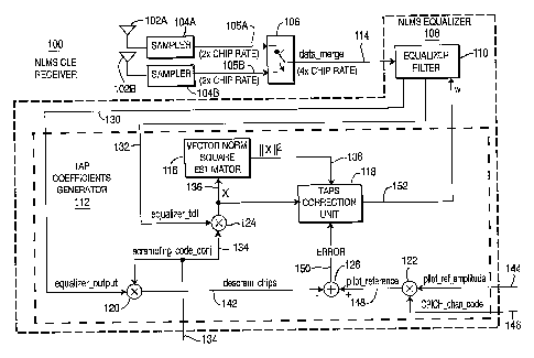
[0022] Figure 1 is a block diagram of an exemplary NLMS CLE receiver
100 configured in accordance with a first embodiment of the present invention.
The NLMS CLE receiver 100 is a joint processing NLMS receiver which uses a
single equalizer filter. The NLMS CLE receiver 100 includes a plurality of
antennas 102A, 102B, a plurality of samplers 104A, 104B, a multiplexer 106 and
an NLMS equalizer 108. The NLMS equalizer 108 includes an equalizer filter
110 and a tap coefficients generator 112.
[0023] Signals received by the antennas 102A, 102B are respectively input
into the samplers 104A, 104B for generating respective sample data streams
105A, 105B which are sampled at two times (2x) the chip rate. The sample data
streams 105A, 105B are merged by the multiplexer 106 into a single sample data
stream 114 which is input into the equalizer filter 110 of the NLMS equalizer
108. Since samples occur at twice the chip rate on each of the sample data
streams 105A, 105B, samples will occur at 4 times (4x) the chip rate on the
sample data stream 114. Each sample that occurs on the sample data stream
114 originated from either sample data stream 105A or 105B. The effective rate
of the equalizer filter 106 is four times (4x) the chip rate.
[0024] Although Figure 1 illustrates the NLMS CLE receiver 100 as being
capable of sampling signals received from two (2) antennas at twice (2x) the
chip
-3-

CA 02585516 2007-04-26
WO 2006/052407 PCT/US2005/037656
rate, it should be noted that the NLMS CLE receiver 100 may comprise any
number of antennas and the signals received by the antennas may be sampled at
any desired rate.
[0025] The equalizer filter 110 comprises a plurality of taps with filter
coefficients. A FIR filter may be utilized as the equalizer filter 110. The
number
of taps in the equalizer filter 110 may be optimized for specific multipath
channels of different power-delay profiles and vehicle speeds. The tap
coefficients
generator 112 includes a vector norm square estimator 116, a taps correction
unit
118, multipliers 120, 122, 124, and an adder 126.
[0026] The equalizer filter 110 outputs an equalizer output signal 130,
which is a chip rate signal. The equalizer output signal 130 is multiplied
with a
scrambling code conjugate signal 134 via the multiplier 120 to generate a
descrambled equalizer output signal 142, (which is an estimate of the
unscrambled transmitted chips). The descrambled equalizer output signa1142 is
input to a first input of the adder 126. The equalizer output signal 130 is
determined based on an equalizer tapped delay line (TDL) signa1132 and a taps
correction signal 152.
[0027] A pilot amplitude reference signa1144 is used to adjust the average
output power of the equalizer 108 by changing the amplitude of a pilot
reference
signal 148, which is generated by the multiplier 122 which multiplies the
pilot
reference amplitude signal 144 with a scaled pilot, (i.e., common pilot
channel
(CPICH)), channelization code 146. The pilot reference signal 148 is input to
a
second input of the adder 126. The descrambled equalizer output signal 142 is
subtracted from the pilot reference signal 148 by the adder 126 to generate an
error signal 150 which is input to a first input of the taps correction unit
118.
The external signals 134, 144 and 146 are configured and generated based on
information signaled from higher layers.
[0028] The equalizer TDL signa1132 is multiplied with the scrambling code
conjugate signa1134 via the multiplier 124 to generate a vector signa1136
having
a value X, which is a descrambled version of signa1132. The vector signa1136
is
input to the vector norm square estimator 116 and to a second input of the
taps
-4-

CA 02585516 2007-04-26
WO 2006/052407 PCT/US2005/037656
correction unit 118. The vector norm square estimator 116 generates a signal
138 having a value which is equal to II X112, (i.e., the norm squared of the
value X
of the vector signal 136, or equivalently the equalizer TDL signal 132). The
vector norm square estimator 116 outputs the signal 138 to a third input of
the
taps correction unit 118. Based on the signals 136, 138 and 150, the taps
correction unit 118 outputs the taps correction signal 152 having a value, w,
which is input to the equalizer filter 110.
[0029] The taps correction signal 152 represents the tap values used by the
equalizer filter 110. At a given time, the next value w of the taps correction
signal 152 is computed by adding to the current value of the taps correction
signal 152, (possibly weighted by a leakage factor), the product of the
normalized
signal, (signal 130 divided by signal 140), and the error signal 150 and a
step size
parameter defined within the taps correction unit 118. A more detailed
mathematical description is provided below.
[0030] The taps correction signa1152 is updated by the taps correction unit
118 as follows:
iH
Wn = a Wii_1 -h 'LL II _ IIZ error, Equation (1)
x -iE
where wn is a weight vector defined for the equalizer filter 110, x, x~ are
vectors
based on the samples received from the antennas 102A, 102B, ,u, a, s are
parameters chosen to control the adaptation step size, tap leakage, and to
prevent division by zero (or near zero) numbers respectively. s is a small
number used to prevent from dividing by zero. The leakage parameter a (alpha)
is a weighting parameter typically not greater than 1. The step size parameter
,u is a scale factor on the error. The equalizer filter 110 is simply a FIR
structure
that computes the inner product of w and X, <w,X>. The result of the inner
product is the equalizer output signal 130.
[0031] The present invention implements receive diversity in conjunction
with an adaptive equalizer, which greatly improves the receiver performance. A
-5-

CA 02585516 2007-04-26
WO 2006/052407 PCT/US2005/037656
joint equalizer filter coefficient vector adaptation scheme in accordance with
the
present invention is described below.
[0032] A joint weight vector wn,jo;,,t is defined for the equalizer filter as
a
union of multiple component weight vectors. Each component weight vector
corresponds to data collected by a different antenna. Any permutation of
elements from component vectors may comprise the joint weight vector so long
as
the permutation properly reflects the order in which data enters the joint
NLMS
equalizer. As these are mathematically equivalent, the permutation may be
chosen for notational convenience. For example, for two antennas, the joint
weight vector wn,joi.t can be defined as follows:
Wn,joint -[Wn,t5w,TZ]T, Equation (2)
where ()T denotes a transpose operation. The total number of taps of the
equalizer
filter is denoted by L. wn, joint is a colunm vector.
[0033] For the chosen notation in Equation (2), the notation for the joint
update vector is defined as follows:
xn jo;.t =[x;,x~], Equation (3)
where x;,zn are vectors based on the samples received from antenna 1 and
antenna 2, respectively. xn jo;nt is a row vector.
[0034] The filter coefficient adaptation for the joint NLMS equalizer can
then be processed in a usual way for an NLMS equalizer. For example, the
updated coefficient vector can be obtained as follows:
_ xHn,joint
Wn+l,joint -a Wn>joint +,ll 2 (d[n]-xn,jointWn,joit
11 x,' j 't 11+~ , Equation (4)
where ()H denotes a transpose conjugate operation, d[n] is the reference
signal for
NLMS and c is a small number used to prevent from dividing by zero. The
parameter a is a weighting parameter and ,u is a scale factor of error signal.
The ,u can be estimated based on the vehicle speed and signal-to-interference
and noise ratio (SINR) and interpolated to obtain a continuous estimation.
-6-

CA 02585516 2007-04-26
WO 2006/052407 PCT/US2005/037656
[0035] For pilot-directed NLMS, d[n] can be a pilot signal, training signal,
or other known pattern signals, either despread signal with pre-determined
despreading factors or non-despread signal. Similarly for data-directed NLMS,
d[n] can be fully-, partially- or non-despread data symbols. The tap
correction
terms 0õ are computed as follows:
_ x
x n,joint
An - ~ 2 e,t,ioint
11 xn,j ~t 11 Equation (5)
~
where the factor eõ ja;nt is a joint error signal and is computed by
subtracting the
equalizer filter output from the reference signal d[n] as follows:
en,joint = d[n] - xn.jointwn,joint . Equation (6)
[0036] The new tap coefficients for the next iteration are obtained by
adding the tap correction terms 0õ to the (weighted) tap coefficients of the
previous iteration. The weighting mechanism can be characterized by a
parameter a (alpha) formulated as follows:
wõ+, = a- wõ + 0õ Equation (7)
[0037] The joint tap update vector in Equation (4) is simply obtained by
substituting the joint weight vector w,,,joit for wn and the joint update
vector
xn,jo;nt for xn into the standard NLMS equation. Equation (4)'uses the joint
equalizer output and subtracts it from the desired signal or pilot signal to
produce joint estimation error. The vector norm square for the input signal is
a
joint vector norm square. The joint estimation error together with the complex
conjugate of input signal, u and vector norm square of input signal produces a
correction term which is added to the tap-weight vector of the iteration n to
produce the tap-weight vector of iteration n+1, the updated tap-weight vector.
[0038] Figure 2 is a block diagram of an exemplary NLMS CLE receiver
200 configured in accordance with a second embodiment of the present
invention.
The NLMS CLE receiver 200 is a despread pilot-directed joint processing NLMS
receiver which uses multiple equalizers. The NLMS CLE receiver 200 includes a
plurality of antennas 202A, 202B, a plurality of samplers 204A, 204B and an
-7-

CA 02585516 2007-04-26
WO 2006/052407 PCT/US2005/037656
NLMS equalizer 206. The NLMS equalizer 206 includes a plurality of equalizer
filters 208A, 208B and a tap coefficients generator 210. Signals received by
the
antennas 202A, 202B are respectively input into the samplers 204A, 204B, which
generate respective sample data streams 205A, 205B, (Xl, X2).
[0039] Although Figure 2 illustrates the NLMS CLE receiver 200 as being
capable of sampling signals received from two (2) antennas at twice (2x) the
chip
rate, it should be understood that the NLMS CLE receiver 200 may comprise any
number of antennas and equalizer filters, and the signals received by the
antennas may be sampled at any desired rate.
[0040] The samples data streams 205A, 205B from the samplers 204A,
204B enter the corresponding equalizer filters 208A, 208B and the tap
coefficients generator 210. The sample data streams 205A, 205B are processed
and down-sampled, (in this example, down-sampled by 2), by the equalizer
filters
208A, 208B to generate equalized signals 212A, 212B at one times (lx) the chip
rate.
[0041] The tap coefficients generator 210 includes serial-to-parallel (S4P)
to vector converters 213A, 213B, multipliers 214A, 214B and 222, vectors
accumulators 216A, 216B, correction term generators 218A, 218B, adders 220
and 226, and a chip accumulator 224. The S4P to vector converters 213A, 213B
are similar to a TDL, whereby the output of the S->P to vector converters
213A,
213B indicates the state of the TDL used to generate the signal output by the
equalizer filter 110 in Figure 1.
[0042] Each of the 2x chip rate sample data streams 205A, 205B is
converted to lx chip rate length L vectors signals 231A, 231B by the S4P to
vector converters 213A, 213B. The length L vectors signals 231A, 231B are then
multiplied with a scrambling code conjugate signal 232, ("P"), via the
multipliers
214A, 214B, respectively, which each outputs a descrambled vectors signal
234A,
234B to respective vectors accumulators 216A, 216B to generate respective
update vectors signals 217A, 217B. The vectors accumulators 216A, 216B
implement a despreading operation over periods, (i.e., the same periods as for
the
chips accumulator 224), that can be other than the spreading factor of the
pilot
-8-

CA 02585516 2007-04-26
WO 2006/052407 PCT/US2005/037656
signal received by the antennas 202A and 202B. The update vectors signals
217A, 217B are forwarded to the correction term generators 218A, 218B.
[0043] The equalized signals 212A, 212B are summed together by the
adder 220 which outputs a summed equalized signa1221. The summed equalized
signa1221 is then multiplied with the scrambling code conjugate signa1232, via
the multiplier 222, which then outputs a descrambled signal 223. The
descrambled signa1223 is fed to the chips accumulator 224, which implements a
despreading operation over periods that can be other than the spreading factor
of
a pilot signal received by the antennas 202A and 202B. The accumulated result
signal 225 output by the chips accumulator 224 is subtracted from a pilot
reference signa1230 by the adder 226 to generate a joint error signa1227.
[0044] Each of the correction term generators 218A, 218B includes a vector
norm square estimator, (not shown, but similar to block 116 shown in Figure
1),
for generating a vector norm square of the update vectors signals 217A, 217B
and
for generating correction terms 219A, 219B based on the update vectors signals
217A, 217B, the vector norm square of the update vectors signals 217A, 217B,
and the joint error signa1227 for the equalizer filters 208A, 208B to be added
to
the filter coefficients of the previous iteration to generate updated filter
coefficients for the next iteration.
[0045] The correction term generator 218A may generate the correction
terms 219A based on the correction term pP = e,ol,,T = Xud 2 which is added in
II Xud,joint II
the equalizer filter 208A to the filter coefficients of the previous iteration
to
generate updated filter coefficients for the next iteration. Likewise, the
correction term generator 218B may generate the correction terms 219B based on
the correction term ,uP = e jo~t X"d which is added in the equalizer filter
I IXud, joint 112
208B to the filter coefficients of the previous iteration to generate updated
filter
coefficients for the next iteration.
-9-

CA 02585516 2007-04-26
WO 2006/052407 PCT/US2005/037656
[0046] Alternatively, the correction term generator 218A may generate the
correction terms 219A based on the correction term ,up = e,o~T = Xud 2 , and
II Xudjoint II +~
the correction term generator 218B may generate the correction terms 219B
based on the correction term ,uP = e j0ll1t = X d Z . The variable 77 is a
II Xud,joint II +,7
relatively small number that is used to improve the numerical properties and
prevent the fixed-point computation from overflow when the correction term is
generated.
[0047] Figure 3 is a block diagram of a simplified version of the NLMS CLE
receiver 200 of Figure 2. The NLMS CLE receiver 300 is a non-despread pilot-
directed joint processing NLMS receiver which uses multiple equalizers. The
NLMS CLE receiver 300 includes a plurality of antennas 302A, 302B, a plurality
of samplers 304A, 304B and an NLMS equalizer 306. The NLMS equalizer 306
includes a plurality of equalizer filters 308A, 308B and a tap coefficients
generator 310. Signals received by the antennas 302A, 302B are respectively
input into the samplers 304A, 304B, which generate respective sample data
streams 305A, 305B.
[0048] Although Figure 3 illustrates the NLMS CLE receiver 300 as being
capable of sampling signals received from two (2) antennas at twice (2x) the
chip
rate, it should be understood that the NLMS CLE receiver 300 may comprise any
number of antennas and equalizer filters, and the signals received by the
antennas may be sampled at any desired chip rate.
[0049] The NLMS CLE receiver 300 of Figure 3 is similar to the NLMS
CLE receiver 200 shown in Figure 2 except that the input sample data stream
and the outputs from the filter coefficients are not accumulated.
[0050] The sample data streams 305A, 305B from the samplers 304A, 304B
enter the corresponding equalizer filters 308A, 308B and the tap coefficients
generator 310. The sample data streams 305A, 305B are processed and down-
sampled, (in this example, down-sampled by 2) by the equalizer filters 308A,
308B to generate equalized signals 312A, 312B at one times (lx) the chip rate.
-10-

CA 02585516 2007-04-26
WO 2006/052407 PCT/US2005/037656
[0051] The tap coefficients generator 310 includes S4 P to vector converters
313A, 313B, multipliers 314A, 314B and 322, correction term generators 318A,
318B and adders 320, 326. Each of the sample data streams 305A, 305B is
converted to length L vectors signals 331A, 331B by the S->P to vector
converters
313A, 313B, which implement a despreading operation over periods that can be
other than the spreading factor of a pilot signal received by the antennas
302A
and 302B. The length L vectors signals 331A, 331B are then multiplied with the
scrambling code conjugate signal 332, ("P"), via the multipliers 314A, 314B,
respectively, to generate descrambled vectors signals 334A, 334B. The
descrambled vectors signals 334A, 334B are respectively forwarded to the
correction term generators 318A, 318B.
[0052] The equalized signals 312A, 312B are summed together by the
adder 320 which outputs a summed equalized signa1321. The summed equalized
signal 321 is then multiplied with a scrambling code conjugate signal 332,
("P"),
via the multiplier 322, which then outputs a descrambled signal 323. The
descrambled signal 323 is subtracted from a reference pilot, (e.g., scaled
pilot),
signal 325 by the adder 326 to generate a joint error signal 327.
[0053] The correction term generators 318A, 318B are similar to the
correction term generators 318A, 318B described in detail above. Each of the
correction term generators 3 18A, 3 18B includes a vector norm square
estimator,
(not shown, but similar to block 116 shown in Figure 1), for generating a
vector
norm square of the descrambled vectors signals 334A, 334B and for generating
correction terms 319A, 319B based on the descrambled vectors 317A, 317B, the
vector norm square of the vector norm square of the descrambled vectors
signals
334A, 334B, and the joint error signal 327 for the equalizer filters 308A,
308B to
be added to the filter coefficients of the previous iteration to generate
updated
filter coefficients for the next iteration.
[0054] The generation of updated filter coefficients used by the NLMS CLE
receivers 200 and 300 are as follows:
-11-

CA 02585516 2007-04-26
WO 2006/052407 PCT/US2005/037656
1 1 1H
~n+l Wn p 1 'xn
_ - 2 2 a + en, oint 2 H
Wn+l wn , II 'xn,joint II +6 xn Equation (8)
a
where en, jo;nt is the joint estimation error resulting from joint processing
of two
antennas and is defined as follows:
(xn 1 2-,2
enjoint = d[n] - l N'n + xn ~'n ) Equation (9)
[0055] A diversity receiver performs the NLMS equalization for each
receiving antenna independently as such:
a ' -F'n + S,,
Equation (10)
a
where w;, and z' are the tap-weight vector and input update vector of the NLMS
equalizer i respectively corresponding to receive antenna i at iteration n.
The
equalizer i generates the error signal of its own and updates the tap-weight
vector independently. The equalizer outputs are despread and combined. For the
pilot-directed method, despread data of multiple antennas are soft combined to
generate the final output for enhanced performance. For the data-directed
method, de-spread data of multiple antennas are soft combined to generate the
final output for hard decision and the resulting hard signal is used as
reference
signal.
[0056] Another variation can be obtained if the tap correction terms 0'n of
Equation (10) are computed by:
.CHn,I
~ n eoint
-'~ 11 x,=>1 112 +~ n,j Equation (11)
and
.xHn,2
~ p II xn,2 112 +6
enjo~t Equation (12)
[0057] Figure 4 is a block diagram of an exemplary NLMS CLE receiver
400 configured in accordance with a third embodiment of the present invention.
The NLMS CLE receiver 400 uses pre-equalization combining of signals received
from the diversity antennas. The NLMS CLE receiver 400 includes a plurality of
antennas 402A, 402B, a plurality of samplers 403A, 403B, a plurality of
matched
-12-

CA 02585516 2007-04-26
WO 2006/052407 PCT/US2005/037656
filters (MFs) 404A, 404B, a plurality of channel estimators 405A, 405B, a
combiner 406 and an NLMS equalizer 408. The NLMS equalizer 408 includes an
equalizer filter 410 and a tap coefficients generator 412.
[0058] Signals are received by the antennas 402 and sample data streams
are generated by the samplers 403 from the received signals. As an example,
Figure 4 illustrates two antennas and sampling at 2x chip rate. However, it
should be noted that the receiver 400 may comprise any number of antennas and
the samples can be generated at any rate. The samples are processed by the
matched filters 404 with channel estimators 405 and combined by the combiner
406 to generate a combined sample data stream 407. The combiner 406 may be a
simple adder with or without weighting. Alternatively, a matched filter may be
used as the combiner 406 to perform the diversity signal combining. The
combined sample data stream 407 remains at the same rate as the sampling rate.
[0059] The combined sample data stream 407 is then fed to the equalizer
filter 408 and the tap coefficients generator 410. Assuming that two antennas
are used, the combined signal can be expressed as follows:
1H 1 2H 2
xn,comb _ - H xn +H 'xn Equation (13)
where H' is the estimated channel response matrix corresponding to the receive
antenna i, where, for the exemplary NLMS CLE receiver 400 which has two
antennas, i=1, 2. The vector xn,,o,,,b is the combined signal vector after the
receive
diversity combining at the iteration n.
[0060] After the diversity combining is performed, a combined sample data
stream 407 is generated and forwarded to the equalizer filter 410 and
processed
to perform equalization to mitigate the interference such as inter-symbol
interference (ISI) and multiple access interference (MAI). In this example,
the
equalizer filter 410 is running at twice (2x) the chip rate and the processed
results are down-sampled by 2 to generate a chip rate output, which is then
descrambled with a scrambling code sequence.
-13-

CA 02585516 2007-04-26
WO 2006/052407 PCT/US2005/037656
[0061] The NLMS can be described in terms of tap-weight vector updates
H
as follows: w = a w + xn,comb d f~ - x w
n+l,comb n,comb P II Z ([] n,comb n,comb )
xn,comb II +E
Equation (14)
where wn,comb is the tap-weight vector for equalizing the combined receiving
signal
and d[n] is the reference signal at time n.
[0062] The tap coefficients generator 412 includes multipliers 411, 420, a
chips accumulator 413, an adder 414, a correction term generator 417, a
vectors
accumulator 422, a multiplier 420 and an S4P to vector converter 418. The
output from the equalizer filter 410 is descrambled via the multiplier 411.
The
output of the multiplier 411 is accumulated by the chips accumulator 413,
which
implements a despreading operation over periods that can be other than the
spreading factor of a pilot signal received by the antennas 402A and 402B. The
accumulated result output by the chips accumulator 413 is subtracted from a
pilot reference signal 415 by the adder 414 to generate a joint error signal
416.
[0063] The combined data sample stream 407 is converted to length L
vectors by the S->P to vector converter 418 and descrambled by the multiplier
420. The descrambled input vectors are accumulated by the vectors accumulator
422 to generate update vectors 423. The vectors accumulator 422 implements a
despreading operation over periods, (i.e., the same periods as for the chips
accumulator 413), that can be other than the spreading factor of the pilot
signal
received by the antennas 402A and 402B. The update vectors 423 are forwarded
to the correction term generator 417. The correction term generator 417
generates correction terms 425 for the equalizer filter 410 to be added to the
filter
coefficients of the previous iteration to generate updated filter coefficients
for the
next iteration.
[0064] The correction term generated by the correction term generator 417
is the product of the normalized signal (signal 423 divided by the norm of
signal
423) and the error signal 416 and a step size parameter (mu) defined within
417.
The new filter values are generated by adding the correction term to the
-14-

CA 02585516 2007-04-26
WO 2006/052407 PCT/US2005/037656
previous filter values. The filter output is an inner product of the filter
values
and the TDL state vector.
[0065] The correction term generator 417 may generate the correction
terms 425 based on the correction term uP - ejoint = II x"d IIZ which is added
in the
Xud
equalizer filter 410 to the filter coefficients of the previous iteration to
generate
updated filter coefficients for the next iteration. Alternatively, the
correction
term generator 417 may generate the correction terms 425 based on the
correction term ,uP = ejoit = X u 2
II Xud II +77
[0066] The foregoing description of the third embodiment shown in Figure
4 is related to a despread pilot-directed receiver. Alternatively, the
receiver may
be a non-despread pilot-directed as shown in Figure 3. In such a case, no
accumulation of the descrambled samples and the received samples streams for
generating an update vector need be performed.
[0067] Although the features and elements of the present invention are
described in particular combinations, each feature or element can be used
alone
without the other features and elements of the preferred embodiments or in
various combinations with or without other features and elements of the
present
invention.
[0068] While the present invention has been described in terms of the
preferred embodiment, other variations which are within the scope of the
invention will be apparent to those skilled in the art.
* x: x~
-15-

Representative Drawing
A single figure which represents the drawing illustrating the invention.
Administrative Status

2024-08-01:As part of the Next Generation Patents (NGP) transition, the Canadian Patents Database (CPD) now contains a more detailed Event History, which replicates the Event Log of our new back-office solution.

Please note that "Inactive:" events refers to events no longer in use in our new back-office solution.

For a clearer understanding of the status of the application/patent presented on this page, the site Disclaimer , as well as the definitions for Patent , Event History , Maintenance Fee  and Payment History  should be consulted.

Event History

Description Date
Inactive: IPC expired 2011-01-01
Application Not Reinstated by Deadline 2009-10-19
Time Limit for Reversal Expired 2009-10-19
Deemed Abandoned - Failure to Respond to Maintenance Fee Notice 2008-10-20
Inactive: Cover page published 2007-07-25
Letter Sent 2007-07-12
Inactive: Acknowledgment of national entry - RFE 2007-07-12
Letter Sent 2007-07-12
Inactive: First IPC assigned 2007-05-17
Application Received - PCT 2007-05-16
National Entry Requirements Determined Compliant 2007-04-26
All Requirements for Examination Determined Compliant 2007-04-26
Request for Examination Requirements Determined Compliant 2007-04-26
National Entry Requirements Determined Compliant 2007-04-26
Application Published (Open to Public Inspection) 2006-05-18

Abandonment History

Abandonment Date Reason Reinstatement Date
2008-10-20

Maintenance Fee

The last payment was received on 2007-09-17

Note : If the full payment has not been received on or before the date indicated, a further fee may be required which may be one of the following

  • the reinstatement fee;
  • the late payment fee; or
  • additional fee to reverse deemed expiry.

Patent fees are adjusted on the 1st of January every year. The amounts above are the current amounts if received by December 31 of the current year.
Please refer to the CIPO Patent Fees web page to see all current fee amounts.

Fee History

Fee Type Anniversary Year Due Date Paid Date
Registration of a document 2007-04-26
Basic national fee - standard 2007-04-26
Request for examination - standard 2007-04-26
MF (application, 2nd anniv.) - standard 02 2007-10-18 2007-09-17
Owners on Record

Note: Records showing the ownership history in alphabetical order.

Current Owners on Record
INTERDIGITAL TECHNOLOGY CORPORATION
Past Owners on Record
ARIELA ZEIRA
KYLE JUNG-LIN PAN
MIHAELA C. BELURI
PHILIP J. PIETRASKI
RUI YANG
Past Owners that do not appear in the "Owners on Record" listing will appear in other documentation within the application.
Documents

To view selected files, please enter reCAPTCHA code :


To view images, click a link in the Document Description column (Temporarily unavailable). To download the documents, select one or more checkboxes in the first column and then click the "Download Selected in PDF format (Zip Archive)" or the "Download Selected as Single PDF" button.

List of published and non-published patent-specific documents on the CPD .

If you have any difficulty accessing content, you can call the Client Service Centre at 1-866-997-1936 or send them an e-mail at CIPO Client Service Centre.

({010=All Documents, 020=As Filed, 030=As Open to Public Inspection, 040=At Issuance, 050=Examination, 060=Incoming Correspondence, 070=Miscellaneous, 080=Outgoing Correspondence, 090=Payment})


Document
Description 
Date
(yyyy-mm-dd) 
Number of pages   Size of Image (KB) 
Description 2007-04-25 15 784
Claims 2007-04-25 17 684
Drawings 2007-04-25 4 137
Abstract 2007-04-25 2 79
Representative drawing 2007-07-24 1 15
Acknowledgement of Request for Examination 2007-07-11 1 177
Reminder of maintenance fee due 2007-07-11 1 112
Notice of National Entry 2007-07-11 1 204
Courtesy - Certificate of registration (related document(s)) 2007-07-11 1 105
Courtesy - Abandonment Letter (Maintenance Fee) 2008-12-14 1 174
PCT 2007-04-25 5 146
Fees 2007-09-16 1 30