Note: Descriptions are shown in the official language in which they were submitted.
CA 02585966 2007-05-02
WO 2006/052047 1 PCT/KR2004/003542
Description
APPARATUS FOR CONTROLLING STANDBY POWER
Technical Field
[11 The present invention relates to an apparatus for controlling standby
power, and
more particularly to a standby power controller for monitoring individual
states of
peripheral devices connected to a computer and a current state of the
computer, and
completely blocking a power-supply voltage from being applied to the
peripheral
devices and the computer according to the monitoring result, such that it
blocks the
occurrence of standby power.
Background Art
[2] Recently, a variety of power-saving electric appliances have been
increasingly
developed to accomplish energy-saving and environment-protection purposes,
such
that they have been widely used thrughout the world. As a variety of power-
saving
electronic fluorescent lamps using a power semiconductor have rapidly come
into
widespread use in the Republic of Korea since the beginning of the 1990's, a
high
power-saving effect has been established in an illumination field. A plurality
of
ccuntries have divided an energy efficiency grade of electric appliances into
first to
fifth energy efficiency grades to allow such energy-saving appliances to come
into
widespread use.
[31 The most important matter to determine the above-mentioned energy
efficiency
grade is standby power.
[4] For example, a TV using a remote-controller is called a preheater,
and is designed
to immediately display a screen image in response to a switching-ON signal or
to
consume remote-control power, such that it unavoidably consumes power on the
condition that a user does not take a TV plug cut of a wall althcugh the user
turns off
the TV.
[51 The amount of standby power occupies about 11% of total household
power
consumption according to academic research. In the case of reducing the amount
of
standby power, annual energy costs can be reduced by about 33,000 Won for each
household, and annual energy costs can be reduced by about 500 billion Won in
the
ccuntry as a whole. In the case of OECD member countries, the amcunt of power
of
abctit 10%-15% of average household power consumption has been consumed as
annual standby power, such that unnecessary consumption of standby power has
been
considered to be the most serious problem of power consumption in the world.
CA 02585966 2011-12-06
- 2 -
[6] The above-mentioned standby power has been unfavorably named "Power
Vampire" by
public opinion organizations in the United States since the occurrence of the
California power
crisis in 2001. The US government has announced the Presidential Order
dictating that products
which do not satisfy the requisite 1-Watt standby power shall be excluded from
governmental
procurement.
[7] European Union (EU) has established a standby power reference by
announcing the lower
Efficiency Principles in Brussels. The Japanese Government has also
established a variety of
rules associated with standby power, such that it has increasingly
concentrated upon
development of improved standby power technologies in conjunction with
associated enterprises.
[8] In the meantime, with the increasing development of computers and the
widespread of
multimedia, a plurality of peripheral devices are connected to the computers
for use in individual
households and offices. For example, a plurality of peripheral devices, for
example, a monitor,
speakers, a printer, a scanner, and a PC camera, etc., are generally connected
to a single
computer. In order to supply a power-supply voltage to the computer and the
peripheral devices,
a multi-concent for use in the computer is generally used.
[9] However, the peripheral devices are used by only a user command
generated when a
computer main body is currently operated, such that the user must directly
power off individual
devices when the computer is not in use, resulting in greater inconvenience of
use. For example,
if a plug of the computer is connected to the socket although the computer is
powered off, i.e., in
the case of a standby time, or if the computer or a specific peripheral device
is not in use for a
long period of time on the condition that the computer is powered on, i.e., in
the case of an idle
time, the user must directly power off individual devices. The amount of power
consumed for the
idle time is greater than that consumed for the standby time, such that it is
considered to be a
very serious problem.
[10] In order to reduce the amount of power consumption during the standby
time, a first method
for mounting a manually-operable switch to the multi-concent to control power
on/off
operations, and a second method for detecting a current of a power-supply
voltage transmitted
from a computer socket to a computer main body, and blocking peripheral
devices from
receiving a power-supply voltage when the computer is powered off are well
known in the art. A
representative example is described in Korean Utility Model Registration No.
20-218843, issued
on 19 January 2001, entitled "Power-Saving Multi-Concent". Korean
CA 02585966 2007-05-02
WO 2006/052047 3 PCT/KR2004/003542
Utility Model Registration No. 20-218843 describes a method for detecting
on/off
states of a computer according to a current detection scheme, and blocks a
power-
supply voltage from being applied to peripheral devices when the computer is
powered
off.
[111 However, in the case of the idle time, i.e., in the case where a
computer or specific
peripheral device is not in use for a long period of time on the condition
that a user
powers on the computer, there is no solution to accomplish the power-saving
effect.
Disclosure of Invention
Technical Problem
[121 Therefore, the present invention has been made in view of the above
problems, and
it is an object of the present invention to provide a standby power control
device for
monitoring state information of peripheral devices connected to a computer and
a
current state of the computer, and controlling power-supply voltages of the
peripheral
devices and the computer according to the monitoring result, such that it
reduces the
amcunt of power consumed for an idle time dating which a user does not
actually use
the computer and at least one peripheral device the to his or her mealtime,
conference,
settlement, and cuting, etc. after the computer and the peripheral devices are
powered
on, and reduces power consumption of the remaining unused peripheral devices
even
when one or more peripheral devices are used, resulting in the implementation
of
complete power-saving effect.
[131 It is another object of the present invention to provide a standby
power control
device for efficiently reducing the amount of standby power (i.e., power
consumption
generated when a plug is connected to a socket although the computer is
powered off)
of a computer and its peripheral devices on the condition that a user powers
off the
computer to leave his or her office or to fall asleep.
Technical Solution
[141 In accordance with the present invention, the above and other objects
can be ac-
complished by the provision of a standby power control apparatus for use in a
power
control device for controlling a power-supply voltage of a computer system
including a
computer and a monitor, and controlling power-supply voltages of peripheral
devices,
for example, a printer, a scanner, a speaker, and a personal computer(PC)
camera, etc.,
the apparatus comprising: a power-supply unit for converting a commercial
power
source to a DC power-supply voltage requisite for the system, and providing
individual
components with necessary power-supply voltages; an interface unit being
connected
CA 02585966 2007-05-02
WO 2006/052047 4 PCT/KR2004/003542
to the computer via a communication line, and interfacing a signal transmitted
from the
computer; an Input/Output (I/0) terminal unit being connected to a mouse and a
keyboard of the computer, and transmitting input signals received from the
mcuse and
the keyboard to a microprocessor; a switching unit for connecting a plurality
of
switches to a plurality of sockets, respectively, switching the switches
according to an
external control signal, and recovering or blocking power-supply voltages
applied to
the sockets; an individual load detector for receiving power-supply state
information
from the switching unit, and detecting load information of the peripheral
device on the
basis of the received power-supply state information; a sensor being mounted
to one
side of the computer or the monitor, and determining the presence or absence
of a user;
a microprocessor for receiving a first input signal from the computer via the
interface
unit, a second input signal from the mcuse and the keyboard via the I/0
terminal unit,
and a third input signal from the individual load detector and the sensor,
switching the
switching unit according to the received first to third input signals, and
controlling a
power-supply voltage generated from the sockets; an individual drive signal
generator
for receiving a control command signal from the microprocessor, and generating
a
drive signal to switch on or off the switches of the switching unit; and a
monitoring/
management unit for determining whether the computer, the monitor, and the
peripheral device are actually used, transmitting a power-supply control
command
signal to the microprocessor via the interface unit according to the
determined result,
and being installed in the computer in the form of an application program,
such that it
provides the user with a variety of administrator setup menus to allow the
user to
control overall operations of the system using the administrator setup menus.
Advantageous Effects
[15] The standby power control device monitors state information of
peripheral devices
connected to a computer and a current state of the computer, and controls
power-
supply voltages of the peripheral devices and the computer according to the
monitoring
result, such that it reduces the amount of power consumed for either an idle
time
dating which a user does not actually use the computer and at least one
peripheral
device the to his or her mealtime, conference, settlement, and outing, etc.
after the
computer and the peripheral devices are powered on, or a standby time after
the system
is terminated, and reduces power consumption of the remaining unused
peripheral
devices even when one or more peripheral devices are used, resulting in the
imple-
mentation of complete power-saving effect. Also, the standby power control
device ef-
ficiently reduces the amount of standby power of the computer and its
peripheral
CA 02585966 2007-05-02
WO 2006/052047 5 PCT/KR2004/003542
devices on the condition that the user powers off the computer to leave his or
her office
or to fall asleep.
Brief Description of the Drawings
[161 The above and other objects, features and other advantages of the
present invention
will be more clearly understood from the following detailed description taken
in
conjunction with the accompanying drawings, in which:
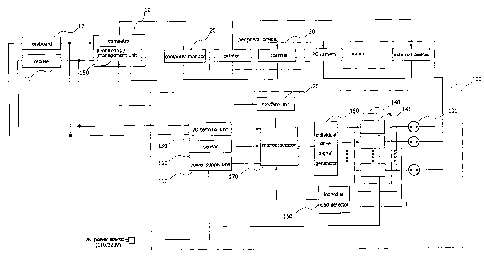
[171 Fig. 1 is a block diagram illustrating a standby power control device
according to
the present invention;
[181 Fig. 2 is a flow chart illustrating a power control method for use in
a monitoring/
management unit contained in the standby power control device of Fig. 1
according to
the present invention; and
[191 Fig. 3 is a flow chart illustrating a power control method for use in
a micro-
processor contained in the standby power control device of Fig. 1 according to
the
present invention.
Mode for the Invention
[201 Now, preferred embodiments of the present invention will be described
in detail
with reference to the annexed drawings. In the drawings, the same or similar
elements
are denoted by the same reference numerals even though they are depicted in
different
drawings. In the following description, a detailed description of known
tnctions and
configirations incorporated herein will be omitted when it may make the
subject
matter of the present invention rather unclear.
[211 Fig. 1 is a block diagram illustrating a standby power control device
according to
the present invention.
[221 Referring to Fig. 1, the standby power control device 100 according
to the present
invention includes a power-supply unit 110, an interface unit 120, an Input/
Output(I/0) terminal unit 130, a switching unit 140, a detector 150 for
detecting
individual load(hereinafter referred to as an individual load detector), a
sensor 160, a
microprocessor 170, an output unit 180 for generating individual drive
signals(hereinafter referred to as an individual drive signal generator), and
a
monitoring/management unit 190.
[231 The power-supply unit 110 converts a 110V or 220V commercial power
source to a
DC power-supply voltage requisite for a system, and provides individual
components
with necessary power-supply voltages. The power-supply unit 110 includes a
rectifier
circuit(not shown) for rectifying an AC voltage to a DC voltage, and a
constant-
CA 02585966 2013-01-11
WO 2006/052047 6 PCT/ICR2004/003542
voltage cirant(not shown) for converting the DC voltage generated from the
rectifier
circuit into a constant DC voltage. Also, the power-supply unit 110 may
receive a DC
voltage from either the interface unit 120 or the computer 10.
[24] The interface unit 120 is connected to the computer via a
communication line, and
interfaces a signal transmitted from the computer 10. In this case, the
interface unit 120
supports a variety of communication schemes, for example, an USB (Universal
Serial
Bus), a PS2, and an RS232, etc.
[25] The I/O terminal unit 130 is connected to a mouse 11 and a keyboard 12
of the
computer 10, and transmits input signals received from the mouse 11 and the
keyboard
12 to the microprocessor 170. In more detail, the I/O terminal unit 130
includes PS2
and IJSB ports to interconnect the mcuse 11 and the keyboard 12, a PS2 port
connected to a P52 port of the computer 10, and an USB port connected to an
USB
port of the computer 10.
[26] The switching unit 140 connects a plurality of switches 141 such as
relays to a
plurality of sockets 101, respectively. The switches 141 are switched by a
drive signal
of the cutput unit for generating individral drive signals, and recovers or
blocks a
commercial power source applied to indivicbal sockets 101. In this case, the
socket
101 includes designated addresses for every peripheral device such that the
micro-
processor 170 independently controls the computer 10, a computer monitor 20,
and a
peripheral device 30. A commercial power source is applied to the switches 141
via
individual sockets 101.
[27] The indivilal load detector 150 receives power-supply state
information from the
switching unit 140, and detects load information of the peripheral device 30
on the
basis of the received power-supply state information. In this case, a user may
monitor
whether the system is normally operated on the basis of the amcunt of load
detected by
the individual load detector 150.
[28] The sensor 160 is mounted to one side of the computer 10 or the
monitor 20 to
determine the presence or absence of a user. In this case, a variety of
sensors may be
used as the sensor 160, for example, a thermal sensor, an optical sensor, a
contact
sensor, and an __ crustic sensor, etc.
[29] The microprocessor 170 receives a first input signal num the computer
10 via the
interface unit 120, a second input signal from the mcuse 11 and the keyboard
12 via
the I/O terminal unit 130, and a third input signal from the indivicbal load
detector 150
and the sensor 160, and switches the switching unit 140 according to the
received first
to third input signals, such that it controls a power-supply voltage generated
from the
CA 025859662007-05-03 PCT/KR
200 4 / 0 0 3 5 42
7
2066
sockets 101. In this case, if the microprocessor 170 receives a first power-
supply
control command, a second power-supply control command, or a third power-
supply
control command, it selectively recovers a power-supply voltage of the
'computer
monitor 20 or the peripheral device 30 or simultaneously recovers the power-
supply
voltages of the computer monitor 20 and the peripheral device 30 according to
the
received power-supply control command information. In this case, the first
power-
supply control command is adapted to selectively recover a power-supply
voltage of
the computer monitor 20 or the peripheral device 30 or simultaneously recover
power-
supply voltages of the computer monitor 20 and the peripheral device 30 on the
condition that the microprocessor 170 receives power-supply recovery commands
of
the computer monitor 20 and the peripheral device 30 from the monitoring/
management unit 190 via the interface unit 120 after the computer monitor 20
and the
peripheral device 30 are powered off. The second power-supply control command
is
adapted to recover a power-supply voltage of a specific peripheral device on
the
condition that the microprocessor 170 determines whether the specific
peripheral
device is used after recognizing used state information of the computer
monitor 20 and
the peripheral device 30 in real time. The third power-supply control command
is
adapted to recover power-supply voltages of the computer monitor 20 and
the peripheral device 30 by allowing the microprocessor 170 to determine
whether an
input signal is generated from the mouse 11 or the keyboard 12.
In the case of the following first to fourth cases, the microprocessor 170
blocks a
power-supply voltage from being applied to the computer 10, the monitor 20,
and the
peripheral device 30. In the first case, a system of the computer 10 is
terminated such
that the monitoring/management unit 190 does not generate a response signal at
least
predetermined number of times. In the second case, there is no input signal
from the
mouse 11 and the keyboard 12 during at least a predetermined time. In the
third case,
when the individual load detector 150 detects the amount of load of the
computer 10,
the computer monitor 20, or the peripheral device 30, it is determined that
the detected
load is less than a predetermined amount of load. In the fourth case, a user
is not
detected by the sensor 160 during at least a predetermined time.
If the user generates an input signal using the keyboard 12 or the mouse 11 on
the
Condition that the computer 10, the computer monitor 20, and the peripheral
device 30
are power off, namely on the condition that standby power is provided, or of
the
presence of the user is detected by the sensor 160, the micro-processor 170
recovers
power-supply voltages of the computer 10, the monitor 20, and the peripheral
device 30.
iAMENDED UEET(ART31)
CA 02585966 2007-05-03 PrVIIR
200 4 1 0 03 5 42
8
09. 1 1. 2006
The microprocessor 170 provides the computer 10 with only standby power when
the presence of the user is detected by the sensor 160 on the condition that
the
computer 10 is powered off. That is, on the condition that the computer is
powered off
so the power is not consumed, standby power is provided thus remains the
condition
of power-off.
The individual drive signal generator 180 receives a control command signal
from
The microprocessor 170, and outputs a drive signal to switch on or off the
switches 141
of the switching unit 140.
The monitoring/management unit 190 determines whether the computer 10 is
actually used or the peripheral device 30 is actually used, outputs a signal
to the micro-
processor 170 via the interface unit 120 according to the determined result.
The
monitoring/management unit 190 is installed in the computer 10 in the form of
an ap-
plication program, such that it provides a user with a variety of
administrator setup
menus to allow the user to control overall operations of the system using the
ad-
ministrator setup menus. In this case, the monitoring/management unit 190
includes
address information when a power-supply control command is transmitted to the
mi-
croprocessor 170.
if the monitoring/management unit 190 transmits a first power-supply control
command, a second power-supply control command, a third power-supply control
command, or a fourth power-supply control command. In this case, the first
power-
supply control command is adapted to selectively or simultaneously block power-
supply voltages of the peripheral device 30 when a user enters a power-supply
blocking command of the peripheral device 30. The second power-supply control
command is adapted to block a power-supply voltage from being applied to a
specific
peripheral device on the condition that used state information of the
peripheral device
30 is recognized in real time and the specific peripheral device is in an idle
state during
a predetermined period. The third power-supply control command is adapted to
block
a power-supply voltage from being applied to a corresponding peripheral device
when
a user manually powers off the corresponding peripheral device. The fourth
power-
supply control command is adapted to block a power-supply voltage from being
applied to the peripheral device 30 if the monitoring/management unit 190
receives no
input signal from the mouse 11 or the keyboard 12 during at least a
predetermined
time.
Contrary to the above-mentioned cases, the monitoring/management unit 190
Generates a first power-supply control command to selectively or
simultaneously
Recover power-supply voltages of the peripheral device 30 when a user enters a
power
____________________ Alt _____
ilDED
,41 :cT (AR 1. ;4/?,)
CA 025859662007-05-03 PCT/KR 200 4 / 0 0 3 5 42
8/1
09, 1 1. 2006
recovery command of the peripheral device 30 using menu information. Also, the
1\ilEMED SHEET (ART. 3 4 )
CA 02585966 2007-05-02
WO 2006/052047 9 PCT/KR2004/003542
monitoring/management unit 190 generates a second power-supply control command
such that it recognizes used state information of the peripheral device 30 in
real time,
determines whether a specific peripheral device is used, and recovers a power-
supply
voltage applied to the specific peripheral device. The monitoring/management
unit 190
generates a third power-supply control command such that it determines whether
an
input signal is generated from the mcuse 11 or the keyboard 12, recovers a
power-
supply voltage of the peripheral device 30 or selectively recovers only power-
supply
voltages of an unused peripheral device other than the used peripheral device
30. In the
case of recovering a power-supply voltage of the peripheral device 30, the
monitoring/
management unit 190 displays a message indicative of a power-supply recovery
on the
computer monitor 20 until the peripheral device 30 recovers its power-supply
voltage
in a warm-up state.
[371 Also, if the monitoring/management unit 190 transmits a first power-
supply control
command, a second power-supply control command, a third power-supply control
command, a fourth power-supply control command, or a fifth power-supply
control
command. In this case, the first power-supply control command is adapted to
block a
power-supply voltage of the computer monitor 20 upon receiving a power-supply
blocking command of the computer monitor 20 from a user. The second power-
supply
control command is adapted to block a power-supply voltage from being applied
to the
computer monitor 20 on the condition that used state information of the
computer
monitor 20 is recognized in real time and the computer monitor 20 is in an
idle state
dating a predetermined period. The third power-supply control command is
adapted to
block a power-supply voltage from being applied to the computer monitor 20
when a
user powers off the computer monitor 20. The fctirth power-supply control
command
is adapted to block a power-supply voltage from being applied to the computer
monitor 20 when there is no input signal from the mouse 11 or the keyboard 12
dating
at least a predetermined time. The fifth power-supply control command is
adapted to
block a power-supply voltage from being applied to the computer monitor 20 if
a
screen saver or a monitor-off operation is activated according to power-supply
setup
information of the monitor 20 from among power-supply option information of
the
computer system.
[381 Contrary to the above-mentioned cases, the monitoring/management unit
190
determines whether an input signal is generated from the mcuse 11 or the
keyboard 12,
recovers a power-supply voltage of the computer monitor 20 according to the
determined result. Otherwise, the monitoring/management unit 190 recognizes
used
CA 02585966 2007-05-02
WO 2006/052047 10 PCT/KR2004/003542
state information(e.g., image data transmission from the computer 10, etc.) of
the
computer monitor 20 in real time, and recovers a power-supply voltage of the
computer monitor 20 according to the recognized state information.
[391 Also, the monitoring/management unit 190 monitors state information
of the
computer 10 on the condition that the peripheral device 30 is powered off,
generates a
command for storing all current tasks if the computer 10 is in an unused
state(e.g., no
download, no file transmission, inactive program state, no data transmission
to
peripheral devices, etc.), stores the current tasks, and terminates the
system. In this
case, the monitoring/management unit 190 turns off an HDD or activates a
system
standby mode according to power-supply option information of a computer system
before the system is terminated. Also, the monitoring/management unit 190
monitors
state information of the computer 10 during a predetermined time, and
terminates the
system if the computer 10 is continuously in the unused state.
[401 Operations of the standby power control device according to the
present invention
will hereinafter be described with reference to Figs. 1 to 3.
[411 Fig. 2 is a flow chart illustrating a power control method for use in
the monitoring/
management unit contained in the standby power control device of Fig. 1
according to
the present invention, and Fig. 3 is a flow chart illustrating a power control
method for
use in the microprocessor contained in the standby power control device of
Fig. 1
according to the present invention.
[421 Prior to describing the present invention, the term "System
Termination'br
"Thwer-Off state'is indicative of a specific state during which system
operations are
completely halted by a user who presses a power Eutton of the system. In the
case of
the system termination or the power-off state, standby power is left in the
system,
resulting in the occurrence of power consumption. And, the other term "Thwer-
Supply
Blocking State'is indicative of a specific state during which an input power
source of
the system is completely blocked, such that there is no power consumption
during the
power-supply blocking state. In other words, the power-supply blocking state
corresponds to an unplugged state.
[431
[441 <DEVICE ADDRESS SETUP>
[451 Individual sockets 101 contained in the standby power control device
100 include
unique designated addresses, respectively. Individual sockets 101 include pre-
determined labels such that they are connected to individual plugs of unique
peripheral
devices 30, for example, a computer monitor 20, a speaker, and a printer, etc.
If a plug
CA 02585966 2007-05-02
WO 2006/052047 11 PCT/KR2004/003542
of one of the peripheral devices 30 is connected to a corresponding socket, an
address
of the peripheral device 30 is determined. This address determination of the
peripheral
device 30 is called a "default setup". In the meantime, provided that a user
desires to
freely establish an address of a specific peripheral device, the user may re-
establish the
address of the peripheral device 30 using the monitoring/management unit 190.
[461
[471 <METHOD FOR CONTROLLING POWER-SUPPLY VOLTAGE OF
PERIPHERAL DEVICE USING MONITORING/MANAGEMENT UNIT>
[481 The computer 10, the computer monitor 20, and the peripheral device
30 are
connected to their designated sockets 101, respectively. The switching unit
140 is
switched on to power on the computer 10, the computer monitor 20, and the
peripheral
device 30, and the computer 10 is booted, such that the system starts its
operation.
[491 Under the above-mentioned situation, if a user selects a
corresponding option menu
to block a power-supply voltage from being applied to a specific peripheral
device or
all peripheral devices using the monitoring/management unit 190 at step S10,
as shown
in Fig. 2, the monitoring/management unit 190 determines which one of
peripheral
devices receives a power-supply blocking command at step S11, determines a
flag of a
corresponding peripheral device to be "1"at step S12, and transmits an address
of a
corresponding peripheral device and a signal including a power-supply control
command for blocking a power-supply voltage to the microprocessor 170 at step
S13.
[501 The monitoring/management unit 190 recognizes used state information
of the
peripheral device 30 in real time dating a first period "periodrat steps S20
and S21,
and determines whether a specific peripheral device is in an idle state during
a pre-
determined time at step S22. If it is determined that the specific peripheral
device is in
the idle state at step S22, the monitoring/management unit 190 determines a
flag of a
corresponding peripheral device to be "1"at step S24, and enters a standby
state during
a maximum standby state allowable time before blocking a power-supply voltage
of
the system at step S25. In this case, provided that the corresponding
peripheral device
is not in the idle state dating the predetermined time and is actually used,
the
monitoring/management unit 190 determines a flag of the corresponding
peripheral
device to be "0"at step S23.
[511 Thereafter, the monitoring/management unit 190 determines whether the
cor-
responding peripheral device is not in use dating a standby allowable time
such as a
second period denoted by "period2", namely, the monitoring/management unit 190
determines whether the flag of the corresponding peripheral device maintains
the value
CA 02585966 2007-05-02
WO 2006/052047 12 PCT/KR2004/003542
of "1"at steps S30 and S31. If it is determined that the flag of the
corresponding
peripheral device maintains the value of "1", the monitoring/management unit
190
transmits an address of the corresponding peripheral device and a signal
including a
power-supply control command for blocking a power-supply voltage to the micro-
processor at step S33. Otherwise, if it is determined that the flag of the
corresponding
peripheral device does not maintain the value of "1", the
monitoring/management unit
190 determines a flag of the corresponding peripheral device to be "0"at step
S32.
[52] The monitoring/management unit 190 determines whether a user manually
turns off
the power-supply voltage of the peripheral device at step S40. If it is
determined that
the user manually turns off the power-supply voltage of the peripheral device
at step
S41, the monitoring/management unit 190 determines the flag of the
corresponding
peripheral device to be "1"at step S42, and transmits an address of the
peripheral
device and a signal including a power-supply control command for blocking a
power-
supply voltage to the microprocessor 170 at step S43.
[53] The monitoring/management unit 190 determines whether no input signal
is
received from the mouse 11 or the keyboard 12 at step S50, and determines
whether
the no input signal state is maintained dating at least a predetermined time
at step S51.
If it is determined that the no input signal state is maintained dating at
least the pre-
determined time at step S51, the monitoring/management unit 190 determines
flags of
all peripheral devices to be the value of"1"at step S52, and transmits
addresses of all
peripheral devices and a signal including a power-supply control command for
blocking a power-supply voltage to the microprocessor 170 at step S53.
[54] Contrary to the above-mentioned operations, if the user enters a power-
supply
recovery command of the peripheral device 30 using menu information, the
monitoring/management unit 190 transmits one of the following first to third
power-
supply control commands. The first power-supply control command selectively or
si-
multanecusly recovers power-supply voltages of the peripheral device 30. The
second
power-supply control command recognizes used state information of the
peripheral
device 30 in real time, determines whether a specific peripheral device is
used, and
recovers a power-supply voltage of the corresponding peripheral device. The
third
power-supply control command determines whether an input signal is generated
from
the mouse 11 or the keyboard 12, recovers all power-supply voltages of all
peripheral
devices 30, or selectively recovers only power-supply voltages of unused
peripheral
devices 30 other than the used peripheral device 30.
[55] However, in the case of a specific peripheral device, for example, a
printer or a
CA 02585966 2007-05-02
WO 2006/052047 13 PCT/KR2004/003542
scanner, an error message occurs when a power-supply voltage is not supplied
to a
peripheral device at the moment at which the computer transmits a service
request to
the peripheral device. In this case, if the peripheral device is in a warm-up
state, the
monitoring/management unit 190 displays a message indicative of a power-supply
recovery, instead of the error message, on the computer monitor 20 until the
power-
supply recovery is finished (e.g., during a device power-supply recovery
completion
time), such that it allows a user to re-transmit a service request to the
above peripheral
device.
[551
[571 <METHOD FOR CONTROLLING POWER-SUPPLY VOLTAGE OF
PERIPHERAL DEVICE USING MICROPROCESSOR>
[581 A method for controlling a power-supply voltage of the peripheral
device using the
microprocessor will hereinafter be described with reference to Fig. 3.
Referring to Fig.
3, if the monitoring/management unit 190 transmits a power-supply control
command
at step S100, the microprocessor 170 determines the number of responses to the
power-supply control command to be "0"at step 5110, analyzes a corresponding
power-supply control command, and determines whether the analyzed power-supply
control command is indicative of a power-supply blocking command at step S120.
If
the corresponding power-supply control command is determined to be the power-
supply blocking command at step S120, the monitoring/management unit 190
analyzes
a signal received from the interface unit 120 to recognize a peripheral
device, a power-
supply voltage of which is to be controlled, and controls the individual drive
signal
generator 180 to switch off the switch 141 of the switching unit 140 connected
to the
socket 101 to which a corresponding peripheral device is connected, such that
it blocks
a power-supply voltage from being applied to the peripheral device connected
to the
socket 101 at step S130. If the microprocessor 170 analyzes a corresponding
power-
supply control command, and determines the analyzed power-supply control
command
to be a power supply command at step S140, it controls the individual drive
signal
generator 180 to turn on the switch 141 of the switching unit 140 connected to
the
socket 101 to which a corresponding peripheral device is connected, and
supplies a
power-supply voltage to the peripheral device connected to the socket 101 at
step 150.
In more detail, the microprocessor 170 receives a power-supply recovery
command of
the user's peripheral device 30 from the monitoring/management unit 190 via
the
interface unit 120 on the condition that the peripheral device 30 is powered
off, and
receives a first power-supply command to selectively or simultaneously recover
CA 02585966 2007-05-02
WO 2006/052047 14 PCT/KR2004/003542
power-supply voltages of the peripheral device 30, such that it selectively or
simul-
tanewsly recovers the power-supply voltages of the peripheral device 30. Also,
the
microprocessor 170 recognizes used state information of the peripheral device
30 in
real time, determines whether a specific peripheral device is used, and
receives a
second power-supply control command to recover a power-supply voltage of the
specific peripheral device, such that it selectively or simultanewsly recovers
the
power-supply voltages of the peripheral device 30. Otherwise, the
microprocessor 170
determines whether an input signal is generated from the mwse 11 or the
keyboard 12,
and receives a third power-supply control command to recover a power-supply
voltage
of the peripheral device 30, such that it selectively or simultanewsly
recovers the
power-supply voltages of the peripheral device 30.
[591 The microprocessor 170 detects the amount of load of the peripheral
device 30
using the individial load detector 150 as shown in the first period denoted by
"periodrof Fig. 3 at steps S200 and S210, compares the detected load with
reference
load, determines whether the detected load is less than the reference load at
step S220,
and blocks a power-supply voltage from being applied to the peripheral device
30.
[601 The microprocessor 170 determines whether a response signal is
received from the
monitoring/management unit 190 as shown in the second period denoted
by"petiod2'bf Fig. 3 at steps S300 and S310, and determines the presence or
absence
of at least three response signals at step S320. If the absence of at least
three response
signal is determined at step S320, the microprocessor 170 returns to step
S230, such
that it controls the individual drive signal generator 180 to turn off the
switch 141 of
the switching unit 140 connected to the socket 101 to which the peripheral
device 30 is
connected at step S230, thereby blocking a power-supply voltage from being
applied
to the peripheral device 30 connected to the socket 101.
[611
[621 <POWER-SUPPLY CONTROL METHOD FOR USE IN COMPUTER
MONITOR>
[631 A power-supply control method for use in a computer monitor using the
monitoring/management unit and the microprocessor will hereinafter be
described. The
monitoring/management unit 190 transmits a power-supply control command to
block
a power-supply voltage from being applied to the computer monitor 20 when a
user
enters a power-supply blocking command of the computer monitor 20.
[641 The monitoring/management unit 190 recognizes used state information
of the
computer monitor 20 in real time, and transmits a first power-supply control
command
CA 02585966 2007-05-02
WO 2006/052047 15 PCT/KR2004/003542
to block a power-supply voltage from being applied to the computer monitor 20
when
the computer monitor 20 is in an idle state dating a predetermined time. If
the user
manually powers off the computer monitor 20, the monitoring/management unit
190
transmits a second power-supply control command to block a power-supply
voltage
from being applied to the computer monitor 20. If an input signal is not
received from
the maise 11 or the keyboard 12 dating at least a predetermined time, the
monitoring/
management unit 190 transmits a third power-supply control command to block a
power-supply voltage from being applied to the computer monitor 20.
[651 If a screen saver or a monitor-off operation is activated according
to monitor
power-supply setup information from among power-supply option information of
the
computer system, the monitoring/management unit 190 transmits a fctirth power-
supply control command to block a power-supply voltage from being applied to
the
computer monitor 20. In other words, if the user activates a system power-
saving mode
or a system protection mode (e.g., a monitor-off tnction or a screen saver
Inchon,
etc., contained in a power-supply management program mainted to a computer
equipped with the EnergyStar logo) using menu information, and selects an
input
power-supply blocking function of the computer monitor 20, the monitoring/
management unit 190 completely blocks an input power-supply voltage from being
applied to the computer monitor 20 in the system power-saving mode or the
system
protection mode.
[661 In the meantime, if the microprocessor 170 determines that a user
does not use the
computer monitor 20 dating a long period of time on the basis of information
received
from the sensor 160 and the individual load detector 150, determines that the
amount
of load is less than reference load because the computer monitor 20 is powered
off, or
determines that an input signal is not received from the maise 11 or the
keyboard 12
dating at least a predetermined time, it blocks a power-supply voltage from
being
applied to the computer monitor 20.
[671 Contrary to the above-mentioned operations, the monitoring/management
unit 190
determines whether an input signal is received from the mouse 11 or the
keyboard 12,
recovers a power-supply voltage of the computer monitor 20 if it is determined
that the
input signal is received from the mouse 11 or the keyboard 12, recognizes used
state
information of the computer monitor 20 in real time, and recovers the power-
supply
voltage of the computer monitor 20 according to the recognized state
information.
[ il I If the user enters a desired input signal using the maise 11 or the
keyboard 12 such
that the microprocessor 170 receives the user entry signal from the 110
terminal unit
CA 02585966 2007-05-02
WO 2006/052047 16 PCT/KR2004/003542
130, or if the sensor 160 detects the presence of the user, the microprocessor
170
recovers a power-supply voltage of the computer monitor 20. In other words,
the mi-
croprocessor 170 receives a power-supply recovery command of the user's
computer
monitor 20 from the monitoring/management unit 190 via the interface unit 120
on the
condition that the computer monitor 20 is powered off, and receives a first
power-
supply command to selectively or simultanewsly recover power-supply voltages
of the
peripheral device 30, such that it recovers the power-supply voltage of the
computer
monitor 20. Also, the microprocessor 170 recognizes used state information of
the
computer monitor 20 in real time, determines whether the computer monitor 20
is
used, and receives a second power-supply control command to recover a power-
supply
voltage of the computer monitor 20, such that it recovers the power-supply
voltage of
the computer monitor 20. Otherwise, the microprocessor 170 determines whether
an
input signal is generated from the mwse 11 or the keyboard 12, and receives a
third
power-supply control command to recover a power-supply voltage of the computer
monitor 20, such that it recovers the power-supply voltage of the computer
monitor 20.
[691
[701 <POWER-SUPPLY CONTROL METHOD FOR USE IN COMPUTER>
[711 A power-supply control method for use in the computer using the
monitoring/
management unit and the microprocessor will hereinafter be described. If all
peripheral
devices 30 are powered off, the microprocessor 170 transmits a first signal
indicative
of a peripheral device power-off message to the monitoring/management unit
190. The
monitoring/management unit 190 directly recognizes used state information of
the
peripheral device 30 in real time, and may transmit a second signal indicative
of a
peripheral device power-off message when all the peripheral devices 30 are
powered
off.
[721 Upon receiving the above-mentioned first signal from the
microprocessor 170, the
monitoring/management unit 190 monitors state information of the computer 10
on the
condition that all peripheral devices 30 are powered off, generates a command
for
storing all current tasks if the computer 10 is in an unused state, stores the
current
tasks, and terminates the system. In this case, the monitoring/management unit
190
turns off an HDD or activates a system standby mode according to power-supply
option information of a computer system before the system is terminated. Also,
the
monitoring/management unit 190 monitors state information of the computer 10
dining
a predetermined time, and terminates the system if the computer 10 is
continuously in
the unused state.
CA 02585966 2007-05-02
WO 2006/052047 17 PCT/KR2004/003542
[731 Until a predetermined second setup time elapses after all power-
supply voltages of
the peripheral devices 30 are completely powered off, if one or more
peripheral
devices are not in use and the computer 10 is in the unused state, the
monitoring/
management unit 190 may generate a command for storing current tasks, may
store the
current tasks, and may terminate the system. Also, the monitoring/management
unit
190 periodically monitors operation state information of the computer 10, and
determines whether I/0 signals are not generated dating at least a
predetermined time.
If it is determined that the I/0 signals are not generated daring at least the
pre-
determined time, the monitoring/management unit 190 may switch a current mode
of
the system to an HDD-off mode or a system standby mode.
[741 If the system is terminated, the microprocessor 170 recognizes a
current state of the
computer 10 using a power-supply blocking method equal to that of the
peripheral
device 30 and the computer monitor 20, such that it blocks a power-supply
voltage
from being applied to the computer 10. In more detail, the microprocessor 170
recognizes the current state of the computer 10 using a method for recognizing
the
number of response signals, a method for comparing load quantities, signals
received
from the mcuse and the keyboard, and signals received from the sensor, etc.,
such that
it blocks a power-supply voltage from being applied to the computer 10. In the
meantime, the microprocessor 170 may independently use the above-mentioned
power-supply blocking method, such that it may perform a system termination
function.
[751 Contrary to the above-mentioned operations, if a user enters a
desired input signal
using the mouse 11 or the keyboard 12 on the condition that the computer 10 is
completely powered off such that the user entry signal is transmitted to the
micro-
processor 170 via the I/0 terminal unit 130, or if the presence of the user is
detected by
the sensor 160, the computer 10 receives only the standby power. However, if
the
computer 10 is completely powered off, even the standby power is not present
in the
computer 10, such that the system is not powered on although the user presses
the
power switch (not shown) of the computer 10. In this case, there is a need to
recover
the standby power of the computer 10, such that only the standby power is
temporarily
supplied to the computer 10 if the sensor 160 determines that the user is
seated in the
front of a computer desk, or the standby power supplied to the computer 10 is
blocked
if the sensor 160 determines that the user leaves the above seat.
[761 In the meantime, in the case of using the above-mentioned standby
power control
device 100, a network-based power-supply control method is made available.
CA 02585966 2007-05-02
WO 2006/052047 18 PCT/KR2004/003542
[771 In more detail, if a plurality of systems are contained in a single
room and a specific
management system is also contained in the same room, the management system
may
completely block a power-supply voltage from being applied to a plurality of
computers and their peripheral devices. Also, the management system transmits
a
message to the standby power control device 100, which is independently used
or is
used for every group, such that it may block an input power-supply voltage
from being
applied to the computer or its peripheral devices connected to the standby
power
control device 100. The above-mentioned operations may be used to allow
schools,
companies, or private educational institutes to simultanewsly control the
power-
supply voltages of their computers or peripheral devices.
[781 Also, the standby power control device 100 according to the present
invention may
be used as a system for automatically controlling a power-supply voltage of
the entire
Wilding. In more detail, the monitoring/management unit is installed in a
central
server for a network system, the standby power control device 100 is designed
to have
a box-shaped high capacity, individual computers, peripheral devices, or
computer/
peripheral device groups are connected to the standby power control device
100, such
that a power-supply management operation and other control operations for the
entire
Wilding may be made available.
Industrial Applicability
[791 As apparent from the above description, the present invention
provides a standby
power control device for monitoring state information of peripheral devices
connected
to a computer and a current state of the computer, and controlling power-
supply
voltages of the peripheral devices and the computer according to the
monitoring result,
such that it reduces the amwnt of power consumed for either an idle time
dating
which a user does not actually use the computer and at least one peripheral
device the
to his or her mealtime, conference, settlement, and outing, etc. after the
computer and
the peripheral devices are powered on, or a standby time after the system is
terminated,
and reduces power consumption of the remaining unused peripheral devices even
when one or more peripheral devices are used, resulting in the implementation
of
complete power-saving effect.
[801 Also, the present invention provides a standby power control device
for efficiently
reducing the amount of standby power of the computer and its peripheral
devices on
the condition that the user powers off the computer to leave his or her office
or to fall
asleep.
[811 Although the preferred embodiments of the present invention have been
disclosed
1
CA 02585966 2011-12-06
-19-
for illustrative purposes, those skilled in the art will appreciate that
various modifications,
additions and substitutions are possible, without departing from the scope of
the
invention as disclosed in the accompanying claims.