Note: Descriptions are shown in the official language in which they were submitted.
CA 02586732 2007-05-04
Method and apparatus for producing membrane electrode units
The present invention relates to the technical field of electrochemistry and
describes a method and an apparatus for producing fuel cell components,
in particular for producing membrane electrode units ("MEUs") for
membrane fuel cells (PEMFC, DMFC) but also for other electrochemical
devices such as electrolysers or sensors.
Fuel cells convert a fuel and an oxidizing agent spatially separated from
one another, at two electrodes, into power, heat and water. Hydrogen, a
hydrogen-rich gas or methanol can serve as the fuel, and oxygen or air as
the oxidizing agent. The process of energy conversion in the fuel cell is
distinguished by a particularly high efficiency. For this reason, fuel cells
in
combination with electric motors are acquiring considerable importance as
an alternative to conventional internal combustion engines. However, they
are also increasingly being used for stationary and portable applications.
The polymer electrolyte membrane fuel cell ("REM" fuel cell) is
distinguished by a compact design, a high power density and a high
efficiency. The technology of the fuel cells is described in detail in the
literature, cf. for example K. Kordesch and G. Simader, "Fuel Cells and
their Applications", VCH Verlag Chemie, Weinheim (Germany) 1996.
A PEM fuel cell stack consists of a stacked arrangement ("stack") of
individual PEM fuel cells, which in turn consist of membrane electrode units
("MEU"s), between which so-called bipolar plates for gas supply and power
conduction are arranged. In order to achieve a certain cell voltage, a large
number of individual membrane electrode units are stacked one behind the
other.
A membrane electrode unit, as described in the present application, has, as
a rule, five layers and consists preferably of an ion-conducting membrane
which is connected on both sides in each case to an electrode ("5-layered
MEU"). Each electrode in turn comprises a gas diffusion substrate, also
known as a gas diffusion layer ("(IDLs"), which is provided with a catalyst
layer.
CA 02586732 2007-05-04
- 2 -
The catalyst layer on the anode is formed for the oxidation of hydrogen, so
the corresponding electrode is referred to as the "anode electrode", or the
"anode" for short.
The catalyst layer on the cathode is formed for the reduction of oxygen.
The corresponding electrode is therefore referred to as the "cathode
electrode", or the "cathode" for short.
The gas diffusion substrates (GDLs) are generally based on substrates
which permit good access of the reaction gases to the electrodes and good
conduction of the cell current. They may consist of porous, electrically
conductive materials, such as carbon fibre paper, carbon fibre nonwovens,
woven carbon fibre fabrics, metal meshes, metallized fibre fabrics and the
like.
For gas-tight sealing of the Ma's on installation in fuel cell stacks, the
MEUs may furthermore contain sealing materials, reinforcing materials or
optionally protective films in the edge region. In this way, more highly
integrated MEU products can also be produced (for example "7-layered
MEUs'').
Bipolar plates (also referred to as "separator plates"), which, as a rule, are
produced from conductive graphite and have channels for the gas supply
and gas removal, are mounted between the MEUs.
Anode and cathode electrodes contain electrocatalysts which catalytically
support the respective reaction (oxidation of hydrogen or reduction of
oxygen). As a rule, noble metal-containing catalysts which contain finely
dispersed noble metals, such as, for example, platinum, palladium,
ruthenium, gold or combinations thereof, are used for this purpose. Carbon
black-supported catalysts of the type Pt/C or PtRu/C, which comprise finely
dispersed platinum or platinum/ruthenium on a conductive carbon black
surface, are preferred. Typical noble metal loads of the catalyst-coated
electrodes are from 0.1 to 0.5 mg Pt/cm2 for the anode side and from 0.2 to
1 mg Pt/cm2 for the cathode side. On the anode side, special PtRu-
containing catalysts are used for operation with reform ate gas.
The ion-conducting membrane preferably consists of proton-conducting
polymer materials. A tetrafluoroethylene/fluorovinyl ether copolymer having
CA 02586732 2007-05-04
- 3 -
acid functions, in particular sulphonic groups, is used with particular
preference. Such a material is sold, for example, under the trade name
Nation by E.I. DuPont. However, it is also possible to use other, in
particular fluorine-free, ionomer materials, such as sulphonated polyether
ketones, sulphonated polyaryl ketones, doped polybenzimidazoles and/or
inorganic ionomers.
Various methods for producing components for fuel cells are described in
the literature:
EP 1 365 464 A2 discloses a continuous process for producing gas
diffusion layers for REM fuel cells. A laminating method is not mentioned.
EP 1 037 295 B1 describes a method for applying electrode layers to an
ionomer membrane in ribbon form by means of a screen printing process.
EP 868 760 B1 discloses a continuous method for producing membrane-
electrode composites. In this case, the ion-conducting membrane is
laminated and bonded with the contacting material in ribbon form in a roller
arrangement.
WO 03/084748 A2 discloses a method and an apparatus for producing
membrane electrode units. The MEUs are in this case produced using an
ionomer membrane in ribbon form by lamination on both sides with
electrodes (i.e. gas diffusion substrates) or catalyst-coated substrates (so-
called "decals"). The electrodes or substrates, previously cut to size in a
punching device, are transported to the laminating location with the aid of
vacuum belts and are laminated there with the polymer electrolyte
membrane. This method has the following disadvantages:
a) The vacuum belts used lead to a high degree of complexity of the
apparatus, which results in higher costs, complicated measurement
and control technology and increased servicing work.
b) The feeding by means of vacuum belts implies transfer locations to the
rollers. As a result, the size of the electrodes is limited in the downward
direction for geometrical reasons; it is not possible to produce MEUs to
any small size that may be desired.
c) The use of vacuum belts limits the heat influencing zone for the
electrodes or substrates to the region of the roller nip. This narrow
heating zone has the effect that there is insufficient heat transmission
CA 02586732 2012-10-19
- 4 -
during the laminating process, in particular if relatively high production
rates have to be realized. The system capacity of such an apparatus is
therefore limited.
The object of the present invention is therefore to provide a simple,
improved method for producing membrane electrode units and to propose
a corresponding improved apparatus.
The object is achieved by a method for producing a membrane
electrode unit which comprises the following steps:
a) Applying the respective electrodes to two neighbouring rollers that
are subjected to a vacuum
b) Feeding the applied electrodes into the roller nip between the two
rollers and
c) Pressing the electrodes with an ion-conducting membrane.
The object is also achieved by a device which has at least two rotating
rollers, the rollers being heatable vacuum rollers.
Furthermore, the object is achieved by a system for producing a membrane
electrode unit comprising one of the devices according to the invention, the
device being coupled to a pick-and-place system.
The present invention avoids the disadvantages of the prior art, in that it
provides a rolling press with heatable vacuum rollers. Consequently, the
vacuum required for fixing the electrode substrates is integrated in the
rolling press. Additional subassemblies such as vacuum belts are no longer
required; the method and device are simplified considerably. Costs for
investment and maintenance are lowered, efficiency is increased. Since the
vacuum belts are no longer required, there are no longer any transfer
locations within the apparatus according to the invention. The size of the
electrodes is consequently not limited in the downward direction, which is
of great benefit in particular against the background of miniaturization
efforts in the fuel cell industry.
CA 02586732 2012-10-19
- 5 -
in particular, the electrodes can be heated through very well after they
have been placed on the vacuum rollers. The heat influencing zone is
considerably extended in comparison with conventional apparatuses; for
this reason, higher operating speeds and higher production rates can be
realized. In spite of an extremely simple configuration, high production
rates with cycle times of around 0.3 seconds can be achieved with the
method described and the associated device.
It has surprisingly been found that the device described can be completely
independent of the dimensions of the electrodes up to the width of its
rollers. The electrodes can be positioned on the vacuum rollers directly by
a commercially available pick-and-place unit. For example, when the
system according to the invention is used, laborious mechanical alignment
is no longer required, if there is a change of format it is just necessary for
example to reprogram a robot that is used. Since this can, for example,
often also take place offline, no setting-up and standstill times occur when
there is a change of format. Additional tool costs are also not incurred.
The electrodes may be cut in advance on a commercially available
diecutting die. Such dies are significantly cheaper than cutting dies for
rotary diecutting. In addition, gas diffusion substrates (GDLs), which are
commercially available only as sheet stock, can be further processed.
Further features and advantages of the present invention are evident
from the subsequent description in conjunction with the appended
drawings, the drawings representing the following:
Figure 1 shows the plan view of the front side of a roller (1) of an
embodiment of the apparatus according to the invention. The bore holes,
which are subjected to a vacuum or blowing air, are covered by
corresponding slides.
Figure 2 shows an axial section of an embodiment of the apparatus
according to the invention.
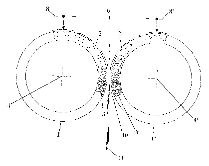
Figure 3 shows a cross section through both rollers (1, 1') of an
embodiment of the apparatus according to the invention during the
production of membrane electrode units.
CA 02586732 2007-05-04
- 6 -
The device according to the invention comprises at least two rotating rollers
(1, 1'), which preferably rotate in a synchronized manner and in opposite
directions. The rollers may be cantilevered and driven on the bearing side,
cf. drive shaft (7). The rollers (1, 1') have vacuum zones (2, 2') and blowing
zones (3, 3'). In a particularly preferred embodiment, the rollers may be
configured as hollow shafts which can be heated to the desired surface
temperature from the inside, for example by means of a controlled infrared
radiator (4). In a further embodiment, however, it is also possible to
configure the heating as electrical heating panels, applied to the inner
surface of the hollow shaft for example with a clamping ring. Typical
surface temperatures of the rollers are in the range from 130 to 220 C,
preferably in range from 150 to 190 C.
The wall of the hollow shaft may be provided with axial distribution bore
holes (5), which can be subjected to vacuum or blowing air in any desired
segments by means of slides located on the front side (the non-mounted
side). From the distribution bore holes, radial bore holes (6) may extend to
the roller surface, the suction effect of which can be used to fix exactly in
position the electrodes placed on the surface of the respective roller. In a
particularly preferred configuration, the rollers are additionally provided
with
a flexible coating, such as for example with silicone rubber, which
increases the width of the pressure influencing zone and reduces the
pressure gradient.
One of the two rollers is preferably formed as a fixed roller. For the
purposes of the invention, a fixed roller means that the fixed roller is the
primarily driven roller and can only perform a rotational movement about its
axis. Electric motors, in particular servomotors or d.c. motors, may be used
for example for the drive. The second roller is preferably formed as a loose
roller, which can be arranged such that it is displaceable transversely to the
roller axis on suitable linear guides. It is also possible to arrange the
loose
roller such that it oscillates on an arc of a circle. To exert the rolling
force,
the loose roller can be adjusted. In a particularly preferred embodiment of
the present invention, this may take place by means of a pneumatic
cylinder; in other embodiments, however, the adjustment may also take
place for example by a hydraulic system or by means of a motor and
spindle. The drive and synchronization of the loose roller may take place by
means of a toothed belt, which may have a tensioning device, or by means
CA 02586732 2007-05-04
- 7 -
of a functionally equivalent machine element. The circumferential speed of
the rollers (1, 1') typically lies in the range from 50 to 500 m/h, preferably
in
the range from 100 to 300 m/h.
The adjustment by means of a force that can be set may be limited by a
displacement stop, which is likewise variable and can be set according to
the requirements of the respective product. For this purpose, an accurate,
electronic displacement measuring means may be attached to the linear
guide. It is also possible, however, to perform the setting for example by
means of a micrometre screw.
=
All the auxiliary units required for operation of the apparatus are preferably
arranged on the bearing side of the rollers. These include, for example, the
drive motor, vacuum station, electrical devices, synchronization of the drive
and adjustment of the loose roller. This arrangement has the advantage
that the front side of the rollers is freely accessible, for example for the
pick-and-place system. In this way it is possible for example to achieve the
minimum possible travelling paths and cycle times for the robot or robots.
In particular, it is readily possible to load both rollers with a single robot
up
to moderate production rates, whereby the efficiency of the apparatus is
once again increased.
The electrodes are preferably available cut-to-size in a magazine, but they
may also be picked from the diecutting base. For example, by means of a
suitable gripper, such as a needle gripper, vacuum gripper or icing gripper,
a correspondingly programmed robot (linear system or SCARA principle)
can pick up the electrode and place it exactly in position on a first roller.
To achieve high accuracies, the position of the electrode on the gripper can
be analysed during the travelling movement by an image processing
system and the robot corrected to correspond to the setpoint value. After
the positionally exact placement of the first electrode, the robot can grip
the
second electrode (possibly from a second magazine) and position it on the
second roller.
In a further embodiment, two robots may also be used for this. In this case,
the two electrodes can be placed exactly at the same time on the apex
points of the first and second rollers by two robots equipped with grippers.
The greater structural complexity is then offset by the advantage that the
CA 02586732 2007-05-04
- 8 -
two electrodes can be placed on the apex points of the two rollers at
synchronized times. By contrast, if a single robot is used, either the rolling
mill has to be stopped for the duration of the pick-and-place process (about
0.5 sec) or else the placement position of the second electrode has to be
computationally corrected by the amount of displacement from a point on
the surface of the roller that has been travelled since the placement of the
first electrode. Up to moderate production rates (depending on the size of
format about 2500 items/h), the cost factor (one robot) can predominate; at
higher production rates, the benefit factor can predominate (two robots).
The electrodes placed exactly position on the rollers (1, 1') are held by
the vacuum applied to the rollers and are fed to the roller nip by the
rotational movement. The first roller is preferably subjected to a vacuum in
the range from approximately 3400 - 90 , the second roller is preferably
subjected to a vacuum in the range from approximately 270 - 20 .
The vacuum used is typically at a negative pressure of 50 to 300 mbars
and can be produced for example by a Venturi nozzle or side-channel
blower. If a side-channel blower is used, no contamination of the air with oil
or water takes place and the exhaust gas of the blower can be used
particularly advantageously as blowing air in the next zone.
The roller nip may be formed by an adjustable stop on the loose roller. The
setting can be performed according to the requirements of the product. The
width of the roller nip is preferably greater than the thickness of the
product,
as to be achieved in the mounted stack under operating conditions. The
limitation of the roller nip avoids inadmissibly high compression of the gas
diffusion layers or electrodes, which could impair the function, and at the
same time ensures that the ion-conducting membrane, which can run as
ribbon-like material between the rollers in the roller nip synchronously with
the circumferential speed of the rollers, is not subjected to loading or
damaged outside the area contacted by the electrodes. The linear load that
is effective during the pressing/laminating lies in the range from 50 to 300
N/cm width of the active area, preferably in the range from 80 to 200 N/cm.
The rolling pressure is preferably applied to the loose roller by one or more
pneumatic cylinders. The rolling pressure may also be exerted by a
hydraulic system or by means of a combination of an electric drive and a
spindle.
CA 02586732 2012-10-19
- 9 -
In the roller nip, the heated-up electrodes, fixed on the rollers by vacuum,
a.(9 brought into contact with the membrane running centrally through the
culler nip as ribbon-like product and bonded under the influence of
temperature and pressure. At this location, the vacuum zone ends and
blowing air is introduced over the following 200 of the circumference
removing the composite that has been produced from the surfaces of the
first and second rollers. In special cases, it is also possible in each case
to
allow an additional separating film to rotate synchronously with the
corresponding roller in order to minimize further the adhesive forces, in
particular of the membrane to the coating of the roller.
After one pass through the rolling mill, the finished composite is available
for further processing. Depending on the form taken by the downstream
process steps, the MEUs located on the membrane ribbon can be passed
on for further processing either in an individually separated form or as
ribbon-like product. The individual separation of the MEUs may take place
discontinuously or continuously by diecutting dies, rotary diecutting dies,
diecutting cutters, perforation rollers or guillotine shears.
In embodiments, the present invention provides:
Item 1) A method for producing a membrane-electrode unit for
membrane fuel cells, comprising an anode electrode (8), a cathode
electrode (8') and an ion-conducting membrane (9) arranged in
between, comprising the following steps:
a) Applying the electrodes (8, 8') to two neighbouring heated
rollers (1, 1') that are subjected to a vacuum,
b) Feeding the applied electrodes (8, 8') into the roller nip (10)
between the two rollers (1, 1'), and
C) Pressing the electrodes (8, 8') with the ion-conducting
membrane (9).
Item 2) A method according to Item 1), further comprising steps for
individually separating the membrane-electrode units.
Item 3) A method according to Item 1) or 2), wherein the vacuum
applied to the two rollers (1, 1') is in the range from 50 to 300 mbar.
Item 4) A method according to any one of Items 1) to 3), wherein the
electrodes (8, 8') consist of gas diffusion substrates which comprise
CA 02586732 2012-10-19
,
=
,
,
- 9a -
porous, electrically conductive materials, such as carbon fibre paper,
carbon fibre nonwovens, woven carbon fibre fabrics, metal meshes,
metallized fibre fabrics and the like and are provided with a catalyst
layer.
Item 5) A method according to any one of Items 1) to 4), wherein the
ion-conducting membrane (9) contains organic ionomers, such as
fluorinated polymeric sulphonic acid derivatives, sulphonated polyether
ketones, sulphonated polyaryl ketones, doped polysulphones, doped
polybenzimidazoles and/or inorganic iononners.
Item 6) A method according to any one of Items 1) to 5), wherein the
electrodes (8, 8') are diecut in advance.
Item 7) A method according to any one of Items 1) to 6), wherein the
electrodes (8, 8') are applied to the rollers (1, 1') with the aid of at least
one robot.
Item 8) A method according to Item 5), wherein the position of the
electrodes (8, 8') on the gripper is analysed during the travelling
movement by an image processing system and the robot is corrected to
correspond to the setpoint value.
Item 9) A method according to any one of Items 1) to 8), wherein the
electrodes (8, 8') are placed on the rollers (1, 1') at synchronized times.
Item 10) A method according to any one of Items 1) to 8), wherein the
electrodes (8, 8') are placed an the rollers (1, V) at times separated by
a delay.
Item 11) A method according to any one of Items 1) to 10), wherein the
pressing of the electrodes (8, 8') with the ion-conducting membrane (9)
takes place with a linear load in the range from 50 to 300 N/cm,
preferably in the range from 80 to 200 N/cm.
Item 12) A method according to any one of Items 1) to 11), wherein the
pressing of the electrodes (8, 8') with the ion-conducting membrane (9)
takes place with a surface temperature of the rolling rollers in the range
from 130 to 220 C, preferably in the range from 150 to 190 C.
CA 02586732 2012-10-19
- 9b -
Item 13) A method according to any one of Items 1) to 12), wherein the
circumferential speed of the rollers (1, 1') is in the range from 50 to 500
m/h, preferably in the range from 100 to 300 m/h.
Item 14) A method according to any one of Items 1) to 13), wherein the
pressing of the respective electrodes is followed by blowing air to the
surface of the rollers (1, 1').
Item 15) A method according to any one of Items 1) to 14), wherein the
membrane-electrode unit is more highly integrated and optionally
comprises sealing materials, reinforcing materials or protective films.
Item 16) A method according to Item 2), wherein the individual
separation takes place by diecutting dies, rotary diecutting dies,
diecutting cutters, perforation rollers or guillotine shears.
Item 17) An apparatus for producing a membrane-electrode unit for
membrane fuel cells, comprising a rolling mill with at least two rotating
rollers (1, 1'), wherein the rollers are heatable vacuum rollers.
Item 18) An apparatus according to Item 17), wherein the apparatus
comprises at least two heat sources (4, 4') for heating the rollers (1, 1').
Item 19) An apparatus according to Item 18), wherein the heat sources
(4, 4') are infrared radiators.
Item 20) An apparatus according to Item 18), wherein the heat sources
(4, 4') are electrical heating panels, applied to the inside of the roller
ring.
Item 21) An apparatus according to any one of Items 17) to 20),
wherein the rollers (1, 1') comprise a number of zones, in particular
vacuum zones (2, 2') and blowing zones (3, 3').
Item 22) An apparatus according to any one of Items 17) to 21),
wherein the respective roller is configured as a hollow shaft and the wall
of the hollow shaft is provided with axial distribution bore holes (5).
Item 23) An apparatus according to any one of Items 17) to 22),
wherein from the axial distribution bore holes (5) radial bore holes (6)
lead to the roller surface.
= CA 02586732 2012-10-19
- 9c -
Item 24) An apparatus according to any one of Items 17) to 22),
wherein the rollers (1, 1') are additionally provided with a flexible
coating, for example silicone rubber.
Item 25) An apparatus according to any one of Items 17) to 24),
wherein one roller is a fixed roller and comprises a drive shaft.
Item 26) An apparatus according to any one of Items 17) to 25),
wherein one roller is a loose roller and the loose roller is mounted on
linear guides such that it is displaceable transversely to the roller axis.
Item 27) An apparatus according to any one of Items 17) to 25),
wherein one roller is a loose roller and the loose roller is guided such
that it oscillates on an arc of a circle transversely to the roller axis.
Item 28) A system for producing a membrane-electrode unit for
membrane fuel cells, wherein the apparatus according to any one of
Items 17) to 27) is coupled to a pick-and-place system.
Item 29) A system for producing a membrane-electrode unit for
membrane fuel cells, wherein the apparatus according to any one of
Items 17) to 27) is coupled to an image processing system.
EXAMPLE
In the present example, a machine which corresponds to the
configurational aspects of the previous sections and has a roller body
diameter of 300 mm is used. To prepare for the production run, a reel of the
ionomer membrane (applied to a carrier film, covered with a protective film;
Nafion NR112, from DuPont; USA) is suspended in the machine and
aligned. The apparatus has a device for delaminating both the carrier film
and the protective film of the membrane, so that said membrane runs freely
into the roller nip.
Furthermore, the anode and cathode electrodes, die-cut to the final
dimensions (also referred to as GCBs -"Catalyst Coated Backings"), are
placed into their respective magazines. The electrodes respectively
comprise a gas diffusion substrate (GDL) of the type SGL Sigracet 30-BC
,from SGL, Meitingen, DE), which is coated with an anode catalyst or
CA 02586732 2007-05-04
- 10 -
cathode catalyst. Carbon black-supported platinum in a formulation which
contains 60% by weight of platinum is used as the catalyst. The suitable
coating processes are known to a person skilled in the art.
Anode and cathode electrodes (CCBs) which have external dimensions of
71 x 71 mm are used. For the materials mentioned in the example, the stop
of the loose roller is set to a distance between the roller surfaces of 600
um, and an adjusting force of 850 N is chosen. The rollers are allowed to
run at a circumferential speed of 160 m/h; the surface temperature is
170 C. The coated CCBs are stored in magazines, from which they are
removed with a gripper. The gripper is mounted on a SCAFIA robot.
The circumferential speed of the rollers in the present example is 44.5
mm/sec (= 160.2 m/h). The first electrode is placed by the robot on the
apex point of the first roller. The second electrode is placed on the second
roller one second later by the same robot in such a way that the centre line
of the second electrode, parallel to the axis of rotation of the roller, lies
44.5
mm closer to the imaginary line of contact of the rollers than the apex point
of the second roller, thereby compensating for the shifting forward of the
first electrode on the first roller. The electrodes are immediately fixed at
the
placement point by the negative pressure of the rollers and released by the
gripper. The rotational movement of the rollers has the effect that the
electrodes are fed to the roller nip exactly in position. The working cycle is
repeated in such a way that there is always the same distance between the
electrodes on the roller surface, corresponding at least to twice the
membrane rim intended for the final product.
In the roller nip, the electrodes fixed on the rollers by negative pressure
are
laminated exactly in position by means of pressure and temperature onto
the membrane guided between them through the roller nip. Those
chambers of the rollers which have passed the roller nip are subjected to
blowing air over a circumferential angle of about 20 , so that the membrane
sheet provided with electrodes easily detaches itself from the two rollers
and runs out freely from the machine. Tension on the membrane sheet
allows the laminates to be easily passed on for further processing, for
example to a diecutting step. In the present example, the final product has
an outer membrane rim of 100 x 100 mm2. Accordingly, 6000 laminates per
hour are obtained.
CA 02586732 2007-05-04
- 1 1 -
List of reference numerals
1/1 roller
2/2' vacuum zone
3/3' blowing zone
4/4' heat source
axial distribution bore hole
6 radial bore hole
7 drive shaft
8/8' electrodes (catalyst-coated anode and cathode)
9 ion-conducting membrane
roller nip
11 membrane-electrode unit
CA 02586732 2007-05-04
Method and apparatus for producing membrane electrode units
The present invention relates to the technical field of electrochemistry and
describes a method and an apparatus for producing fuel cell components,
in particular for producing membrane electrode units ("MEUs") for
membrane fuel cells (PEMFC, DMFC) but also for other electrochemical
devices such as electrolysers or sensors.
Fuel cells convert a fuel and an oxidizing agent spatially separated from
one another, at two electrodes, into power, heat and water. Hydrogen, a
hydrogen-rich gas or methanol can serve as the fuel, and oxygen or air as
the oxidizing agent. The process of energy conversion in the fuel cell is
distinguished by a particularly high efficiency. For this reason, fuel cells
in
combination with electric motors are acquiring considerable importance as
an alternative to conventional internal combustion engines. However, they
are also increasingly being used for stationary and portable applications.
The polymer electrolyte membrane fuel cell ("REM" fuel cell) is
distinguished by a compact design, a high power density and a high
efficiency. The technology of the fuel cells is described in detail in the
literature, cf. for example K. Kordesch and G. Simader, "Fuel Cells and
their Applications", VCH Verlag Chemie, Weinheim (Germany) 1996.
A PEM fuel cell stack consists of a stacked arrangement ("stack") of
individual PEM fuel cells, which in turn consist of membrane electrode units
("MEU"s), between which so-called bipolar plates for gas supply and power
conduction are arranged. In order to achieve a certain cell voltage, a large
number of individual membrane electrode units are stacked one behind the
other.
A membrane electrode unit, as described in the present application, has, as
a rule, five layers and consists preferably of an ion-conducting membrane
which is connected on both sides in each case to an electrode ("5-layered
MEU"). Each electrode in turn comprises a gas diffusion substrate, also
known as a gas diffusion layer ("(IDLs"), which is provided with a catalyst
layer.
CA 02586732 2007-05-04
- 2 -
The catalyst layer on the anode is formed for the oxidation of hydrogen, so
the corresponding electrode is referred to as the "anode electrode", or the
"anode" for short.
The catalyst layer on the cathode is formed for the reduction of oxygen.
The corresponding electrode is therefore referred to as the "cathode
electrode", or the "cathode" for short.
The gas diffusion substrates (GDLs) are generally based on substrates
which permit good access of the reaction gases to the electrodes and good
conduction of the cell current. They may consist of porous, electrically
conductive materials, such as carbon fibre paper, carbon fibre nonwovens,
woven carbon fibre fabrics, metal meshes, metallized fibre fabrics and the
like.
For gas-tight sealing of the Ma's on installation in fuel cell stacks, the
MEUs may furthermore contain sealing materials, reinforcing materials or
optionally protective films in the edge region. In this way, more highly
integrated MEU products can also be produced (for example "7-layered
MEUs'').
Bipolar plates (also referred to as "separator plates"), which, as a rule, are
produced from conductive graphite and have channels for the gas supply
and gas removal, are mounted between the MEUs.
Anode and cathode electrodes contain electrocatalysts which catalytically
support the respective reaction (oxidation of hydrogen or reduction of
oxygen). As a rule, noble metal-containing catalysts which contain finely
dispersed noble metals, such as, for example, platinum, palladium,
ruthenium, gold or combinations thereof, are used for this purpose. Carbon
black-supported catalysts of the type Pt/C or PtRu/C, which comprise finely
dispersed platinum or platinum/ruthenium on a conductive carbon black
surface, are preferred. Typical noble metal loads of the catalyst-coated
electrodes are from 0.1 to 0.5 mg Pt/cm2 for the anode side and from 0.2 to
1 mg Pt/cm2 for the cathode side. On the anode side, special PtRu-
containing catalysts are used for operation with reform ate gas.
The ion-conducting membrane preferably consists of proton-conducting
polymer materials. A tetrafluoroethylene/fluorovinyl ether copolymer having
CA 02586732 2007-05-04
- 3 -
acid functions, in particular sulphonic groups, is used with particular
preference. Such a material is sold, for example, under the trade name
Nation by E.I. DuPont. However, it is also possible to use other, in
particular fluorine-free, ionomer materials, such as sulphonated polyether
ketones, sulphonated polyaryl ketones, doped polybenzimidazoles and/or
inorganic ionomers.
Various methods for producing components for fuel cells are described in
the literature:
EP 1 365 464 A2 discloses a continuous process for producing gas
diffusion layers for REM fuel cells. A laminating method is not mentioned.
EP 1 037 295 B1 describes a method for applying electrode layers to an
ionomer membrane in ribbon form by means of a screen printing process.
EP 868 760 B1 discloses a continuous method for producing membrane-
electrode composites. In this case, the ion-conducting membrane is
laminated and bonded with the contacting material in ribbon form in a roller
arrangement.
WO 03/084748 A2 discloses a method and an apparatus for producing
membrane electrode units. The MEUs are in this case produced using an
ionomer membrane in ribbon form by lamination on both sides with
electrodes (i.e. gas diffusion substrates) or catalyst-coated substrates (so-
called "decals"). The electrodes or substrates, previously cut to size in a
punching device, are transported to the laminating location with the aid of
vacuum belts and are laminated there with the polymer electrolyte
membrane. This method has the following disadvantages:
a) The vacuum belts used lead to a high degree of complexity of the
apparatus, which results in higher costs, complicated measurement
and control technology and increased servicing work.
b) The feeding by means of vacuum belts implies transfer locations to the
rollers. As a result, the size of the electrodes is limited in the downward
direction for geometrical reasons; it is not possible to produce MEUs to
any small size that may be desired.
c) The use of vacuum belts limits the heat influencing zone for the
electrodes or substrates to the region of the roller nip. This narrow
heating zone has the effect that there is insufficient heat transmission
CA 02586732 2007-05-04
- 4 -
during the laminating process, in particular if relatively high production
rates have to be realized. The system capacity of such an apparatus is
therefore limited.
The object of the present invention is therefore to provide a simple,
improved method for producing membrane electrode units and to propose
a corresponding improved apparatus.
This object is achieved by the invention with the features of the
independent claims. Advantageous embodiments of the invention are
characterized in the subclaims.
In particular, the object is achieved by a method for producing a membrane
electrode unit which comprises the following steps:
a) Applying the respective electrodes to two neighbouring rollers that
are subjected to a vacuum
b) Feeding the applied electrodes into the roller nip between the two
rollers and
c) Pressing the electrodes with an ion-conducting membrane.
The object is also achieved by a device which has at least two rotating
rollers, the rollers being heatable vacuum rollers.
Furthermore, the object is achieved by a system for producing a membrane
electrode unit comprising one of the devices according to the invention, the
device being coupled to a pick-and-place system.
The present invention avoids the disadvantages of the prior art, in that it
provides a rolling press with heatable vacuum rollers. Consequently, the
vacuum required for fixing the electrode substrates is integrated in the
rolling press. Additional subassemblies such as vacuum belts are no longer
required; the method and device are simplified considerably. Costs for
investment and maintenance are lowered, efficiency is increased. Since the
vacuum belts are no longer required, there are no longer any transfer
locations within the apparatus according to the invention. The size of the
electrodes is consequently not limited in the downward direction, which is
of great benefit in particular against the background of miniaturization
efforts in the fuel cell industry.
CA 02586732 2007-05-04
- 5 -
In particular, the electrodes can be heated through very well after they
have been placed on the vacuum rollers. The heat influencing zone is
considerably extended in comparison with conventional apparatuses; for
this reason, higher operating speeds and higher production rates can be
realized. In spite of an extremely simple configuration, high production
rates with cycle times of around 0.3 seconds can be achieved with the
method described and the associated device.
It has surprisingly been found that the device described can be completely
independent of the dimensions of the electrodes up to the width of its
rollers. The electrodes can be positioned on the vacuum rollers directly by
a commercially available pick-and-place unit. For example, when the
system according to the invention is used, laborious mechanical alignment
is no longer required, if there is a change of format it is just necessary for
example to reprogram a robot that is used. Since this can, for example,
often also take place offline, no setting-up and standstill times occur when
there is a change of format. Additional tool costs are also not incurred.
The electrodes may be cut in advance on a commercially available
diecutting die. Such dies are significantly cheaper than cutting dies for
rotary diecutting. In addition, gas diffusion substrates (GDLs), which are
commercially available only as sheet stock, can be further processed.
Further features and advantages of the present invention are evident from
the subsequent description and the accompanying claims in conjunction
with the appended drawings, the drawings representing the following:
Figure 1 shows the plan view of the front side of a roller (1) of an
embodiment of the apparatus according to the invention. The bore holes,
which are subjected to a vacuum or blowing air, are covered by
corresponding slides.
Figure 2 shows an axial section of an embodiment of the apparatus
according to the invention.
Figure 3 shows a cross section through both rollers (1, 1') of an
embodiment of the apparatus according to the invention during the
production of membrane electrode units.
CA 02586732 2007-05-04
- 6 -
The device according to the invention comprises at least two rotating rollers
(1, 1'), which preferably rotate in a synchronized manner and in opposite
directions. The rollers may be cantilevered and driven on the bearing side,
cf. drive shaft (7). The rollers (1, 1') have vacuum zones (2, 2') and blowing
zones (3, 3'). In a particularly preferred embodiment, the rollers may be
configured as hollow shafts which can be heated to the desired surface
temperature from the inside, for example by means of a controlled infrared
radiator (4). In a further embodiment, however, it is also possible to
configure the heating as electrical heating panels, applied to the inner
surface of the hollow shaft for example with a clamping ring. Typical
surface temperatures of the rollers are in the range from 130 to 220 C,
preferably in range from 150 to 190 C.
The wall of the hollow shaft may be provided with axial distribution bore
holes (5), which can be subjected to vacuum or blowing air in any desired
segments by means of slides located on the front side (the non-mounted
side). From the distribution bore holes, radial bore holes (6) may extend to
the roller surface, the suction effect of which can be used to fix exactly in
position the electrodes placed on the surface of the respective roller. In a
particularly preferred configuration, the rollers are additionally provided
with
a flexible coating, such as for example with silicone rubber, which
increases the width of the pressure influencing zone and reduces the
pressure gradient.
One of the two rollers is preferably formed as a fixed roller. For the
purposes of the invention, a fixed roller means that the fixed roller is the
primarily driven roller and can only perform a rotational movement about its
axis. Electric motors, in particular servomotors or d.c. motors, may be used
for example for the drive. The second roller is preferably formed as a loose
roller, which can be arranged such that it is displaceable transversely to the
roller axis on suitable linear guides. It is also possible to arrange the
loose
roller such that it oscillates on an arc of a circle. To exert the rolling
force,
the loose roller can be adjusted. In a particularly preferred embodiment of
the present invention, this may take place by means of a pneumatic
cylinder; in other embodiments, however, the adjustment may also take
place for example by a hydraulic system or by means of a motor and
spindle. The drive and synchronization of the loose roller may take place by
means of a toothed belt, which may have a tensioning device, or by means
CA 02586732 2007-05-04
- 7 -
of a functionally equivalent machine element. The circumferential speed of
the rollers (1, 1') typically lies in the range from 50 to 500 m/h, preferably
in
the range from 100 to 300 m/h.
The adjustment by means of a force that can be set may be limited by a
displacement stop, which is likewise variable and can be set according to
the requirements of the respective product. For this purpose, an accurate,
electronic displacement measuring means may be attached to the linear
guide. It is also possible, however, to perform the setting for example by
means of a micrometre screw.
=
All the auxiliary units required for operation of the apparatus are preferably
arranged on the bearing side of the rollers. These include, for example, the
drive motor, vacuum station, electrical devices, synchronization of the drive
and adjustment of the loose roller. This arrangement has the advantage
that the front side of the rollers is freely accessible, for example for the
pick-and-place system. In this way it is possible for example to achieve the
minimum possible travelling paths and cycle times for the robot or robots.
In particular, it is readily possible to load both rollers with a single robot
up
to moderate production rates, whereby the efficiency of the apparatus is
once again increased.
The electrodes are preferably available cut-to-size in a magazine, but they
may also be picked from the diecutting base. For example, by means of a
suitable gripper, such as a needle gripper, vacuum gripper or icing gripper,
a correspondingly programmed robot (linear system or SCARA principle)
can pick up the electrode and place it exactly in position on a first roller.
To achieve high accuracies, the position of the electrode on the gripper can
be analysed during the travelling movement by an image processing
system and the robot corrected to correspond to the setpoint value. After
the positionally exact placement of the first electrode, the robot can grip
the
second electrode (possibly from a second magazine) and position it on the
second roller.
In a further embodiment, two robots may also be used for this. In this case,
the two electrodes can be placed exactly at the same time on the apex
points of the first and second rollers by two robots equipped with grippers.
The greater structural complexity is then offset by the advantage that the
CA 02586732 2007-05-04
- 8 -
two electrodes can be placed on the apex points of the two rollers at
synchronized times. By contrast, if a single robot is used, either the rolling
mill has to be stopped for the duration of the pick-and-place process (about
0.5 sec) or else the placement position of the second electrode has to be
computationally corrected by the amount of displacement from a point on
the surface of the roller that has been travelled since the placement of the
first electrode. Up to moderate production rates (depending on the size of
format about 2500 items/h), the cost factor (one robot) can predominate; at
higher production rates, the benefit factor can predominate (two robots).
The electrodes placed exactly position on the rollers (1, 1') are held by
the vacuum applied to the rollers and are fed to the roller nip by the
rotational movement. The first roller is preferably subjected to a vacuum in
the range from approximately 3400 - 90 , the second roller is preferably
subjected to a vacuum in the range from approximately 270 - 20 .
The vacuum used is typically at a negative pressure of 50 to 300 mbars
and can be produced for example by a Venturi nozzle or side-channel
blower. If a side-channel blower is used, no contamination of the air with oil
or water takes place and the exhaust gas of the blower can be used
particularly advantageously as blowing air in the next zone.
The roller nip may be formed by an adjustable stop on the loose roller. The
setting can be performed according to the requirements of the product. The
width of the roller nip is preferably greater than the thickness of the
product,
as to be achieved in the mounted stack under operating conditions. The
limitation of the roller nip avoids inadmissibly high compression of the gas
diffusion layers or electrodes, which could impair the function, and at the
same time ensures that the ion-conducting membrane, which can run as
ribbon-like material between the rollers in the roller nip synchronously with
the circumferential speed of the rollers, is not subjected to loading or
damaged outside the area contacted by the electrodes. The linear load that
is effective during the pressing/laminating lies in the range from 50 to 300
N/cm width of the active area, preferably in the range from 80 to 200 N/cm.
The rolling pressure is preferably applied to the loose roller by one or more
pneumatic cylinders. The rolling pressure may also be exerted by a
hydraulic system or by means of a combination of an electric drive and a
spindle.
CA 02586732 2007-05-04
- 9 -
In the roller nip, the heated-up electrodes, fixed on the rollers by vacuum,
are brought into contact with the membrane running centrally through the
roller nip as ribbon-like product and bonded under the influence of
temperature and pressure. At this location, the vacuum zone ends and
blowing air is introduced over the following 200 of the circumference,
removing the composite that has been produced from the surfaces of the
first and second rollers. In special cases, it is also possible in each case
to
allow an additional separating film to rotate synchronously with the
corresponding roller in order to minimize further the adhesive forces, in
particular of the membrane to the coating of the roller.
After one pass through the rolling mill, the finished composite is available
for further processing. Depending on the form taken by the downstream
process steps, the MEUs located on the membrane ribbon can be passed
on for further processing either in an individually separated form or as
ribbon-like product. The individual separation of the MEUs may take place
discontinuously or continuously by diecutting dies, rotary diecutting dies,
diecutting cutters, perforation rollers or guillotine shears.
EXAMPLE
In the present example, a machine which corresponds to the
configurational aspects of the previous sections and has a roller body
diameter of 300 mm is used. To prepare for the production run, a reel of the
ionomer membrane (applied to a carrier film, covered with a protective film;
Nafion NR112, from DuPont; USA) is suspended in the machine and
aligned. The apparatus has a device for delaminating both the carrier film
and the protective film of the membrane, so that said membrane runs freely
into the roller nip.
Furthermore, the anode and cathode electrodes, die-cut to the final
dimensions (also referred to as CCBs -Catalyst Coated Backings"), are
placed into their respective magazines. The electrodes respectively
comprise a gas diffusion substrate (GDL) of the type SGL Sigracet 30-BC
(from SGL, Meitingen, DE), which is coated with an anode catalyst or
CA 02586732 2007-05-04
- 10 -
cathode catalyst. Carbon black-supported platinum in a formulation which
contains 60% by weight of platinum is used as the catalyst. The suitable
coating processes are known to a person skilled in the art.
Anode and cathode electrodes (CCBs) which have external dimensions of
71 x 71 mm are used. For the materials mentioned in the example, the stop
of the loose roller is set to a distance between the roller surfaces of 600
um, and an adjusting force of 850 N is chosen. The rollers are allowed to
run at a circumferential speed of 160 m/h; the surface temperature is
170 C. The coated CCBs are stored in magazines, from which they are
removed with a gripper. The gripper is mounted on a SCAFIA robot.
The circumferential speed of the rollers in the present example is 44.5
mm/sec (= 160.2 m/h). The first electrode is placed by the robot on the
apex point of the first roller. The second electrode is placed on the second
roller one second later by the same robot in such a way that the centre line
of the second electrode, parallel to the axis of rotation of the roller, lies
44.5
mm closer to the imaginary line of contact of the rollers than the apex point
of the second roller, thereby compensating for the shifting forward of the
first electrode on the first roller. The electrodes are immediately fixed at
the
placement point by the negative pressure of the rollers and released by the
gripper. The rotational movement of the rollers has the effect that the
electrodes are fed to the roller nip exactly in position. The working cycle is
repeated in such a way that there is always the same distance between the
electrodes on the roller surface, corresponding at least to twice the
membrane rim intended for the final product.
In the roller nip, the electrodes fixed on the rollers by negative pressure
are
laminated exactly in position by means of pressure and temperature onto
the membrane guided between them through the roller nip. Those
chambers of the rollers which have passed the roller nip are subjected to
blowing air over a circumferential angle of about 20 , so that the membrane
sheet provided with electrodes easily detaches itself from the two rollers
and runs out freely from the machine. Tension on the membrane sheet
allows the laminates to be easily passed on for further processing, for
example to a diecutting step. In the present example, the final product has
an outer membrane rim of 100 x 100 mm2. Accordingly, 6000 laminates per
hour are obtained.
CA 02586732 2007-05-04
- 1 1 -
List of reference numerals
1/1 roller
2/2' vacuum zone
3/3' blowing zone
4/4' heat source
axial distribution bore hole
6 radial bore hole
7 drive shaft
8/8' electrodes (catalyst-coated anode and cathode)
9 ion-conducting membrane
roller nip
11 membrane-electrode unit