Language selection

Search

Patent 2587045 Summary

Third-party information liability

Some of the information on this Web page has been provided by external sources. The Government of Canada is not responsible for the accuracy, reliability or currency of the information supplied by external sources. Users wishing to rely upon this information should consult directly with the source of the information. Content provided by external sources is not subject to official languages, privacy and accessibility requirements.

Claims and Abstract availability

Any discrepancies in the text and image of the Claims and Abstract are due to differing posting times. Text of the Claims and Abstract are posted:

  • At the time the application is open to public inspection;
  • At the time of issue of the patent (grant).
(12) Patent Application: (11) CA 2587045
(54) English Title: BICYCLE RACK WITH WHEEL SECURING DEVICES
(54) French Title: SUPPORT A BICYCLETTES AVEC DISPOSITIFS DE FIXATION DES ROUES
Status: Deemed Abandoned and Beyond the Period of Reinstatement - Pending Response to Notice of Disregarded Communication
Bibliographic Data
(51) International Patent Classification (IPC):
  • B60R 09/10 (2006.01)
  • B62H 03/04 (2006.01)
  • B62H 03/06 (2006.01)
(72) Inventors :
  • WANG, CHIU-KUEI (Taiwan, Province of China)
(73) Owners :
  • CHIU-KUEI WANG
(71) Applicants :
  • CHIU-KUEI WANG (Taiwan, Province of China)
(74) Agent: PERLEY-ROBERTSON, HILL & MCDOUGALL LLP
(74) Associate agent:
(45) Issued:
(22) Filed Date: 2007-05-02
(41) Open to Public Inspection: 2007-11-02
Availability of licence: N/A
Dedicated to the Public: N/A
(25) Language of filing: English

Patent Cooperation Treaty (PCT): No

(30) Application Priority Data:
Application No. Country/Territory Date
095207487 (Taiwan, Province of China) 2006-05-02

Abstracts

English Abstract


A bicycle rack a frame and two side rods pivotably connected to two sides of
the frame and two wheel securing devices are connected to the two side rods
respectively. Each wheel securing device includes a wheel retaining unit which
has a
U-shaped member with which the front wheel or the rear wheel is retained. A
post is
pivotably connected to a top of the frame and a frame securing unit is
connected to
the post so as to position the bicycle frame.


Claims

Note: Claims are shown in the official language in which they were submitted.


WHAT IS CLAIMED IS:
1. A bicycle rack comprising:
a connection portion (10) including a frame (11) on a first end thereof and a
second end of the connection portion (10) adapted to be connected with a
connection tube (50) on a vehicle by a securing unit (12);
two side rods (21) pivotably connected to two sides of the frame (11) and
two wheel securing devices (20) connected to the two side rods (21)
respectively,
each wheel securing device (20) including a wheel retaining units (23) which
has a
U-shaped member (233), and
a post (31) pivotably connected to a top of the frame (11) and a frame
securing unit (30) connected to the post (31), the frame securing unit (30)
including a
securing member (33) which is movably connected to the post (31).
2. The bicycle rack as claimed in claim 1, wherein the securing unit (12)
includes a U-shaped member (13) mounted to the second end of the connection
portion (10) and a pin (14) extends through the U-shaped member (13) and the
second end of the connection portion (10) so as to be adapted to connect the
connection tube (50).
3. The bicycle rack as claimed in claim 1, wherein the wheel retaining units
(23) of each of the wheel securing devices (20) includes a bar (231), a
locking set
(232) connected to an end of the bar (231) and the U-shaped member (233)
extending from the bar (231), the locking set (232) is movably connected to
the side
rod (21).
4. The bicycle rack as claimed in claim 3, wherein the locking set (232) is
cooperated with a locking assembly (24) which includes two clamping members so
as to clamp the side rod (21) therebetween and a threaded rod (241) extend
through the two clamping members, a knob (242) is threadedly connected to the
threaded rod (241).
5. The bicycle rack as claimed in claim 3 further comprising a securing belt
(243) mounted to the bar (231).
6. The bicycle rack as claimed in claim 1, wherein the frame securing unit
(30)
includes a locking set (32) which is movably mounted to the post (31) and a
securing

member (33) is connected to the locking set (32), the securing member (33)
includes
a rod (331) and a hook (333).
7. The bicycle rack as claimed in claim 6, wherein the locking set (32) is
cooperated with a positioning set (34) which includes a threaded rod (341)
extending
through two clamping members of the locking set (32) and a knob (342) is
threadedly
connected to the threaded rod (341).
8. The bicycle rack as claimed in claim 1, wherein the frame (11) includes two
side recesses (111) and a top recess (112), the two side rods (21) are
pivotably
engaged with the two side recesses (111) and positioned by a positioning
arrangement (22), the post (31) is pivotably engaged with the top recess
(112).
9. The bicycle rack as claimed in claim 8, wherein each of the two side
recesses (111) is composed of two sidewalls and the positioning arrangement
(22)includes a first hole (222) and a second hole (223) defined in each of the
sidewalls, each of the two side rods (21) includes two positioning holes
(221), one of
the two positioning holes (221) is aligned with one of the first and second
holes
(222, 223), a pin (225) extends through the aligned positioning hole (221) and
one
of the first and second holes (222, 223).
10. The bicycle rack as claimed in claim 9, wherein each of first and second
holes (222, 223) and the positioning holes (221) communicates with respective
one of
notches (224) and the pin (225) is an L-shaped pin which includes a protrusion
(226) which extends through the notches (224) and the pin (225) is rotated
angle to
move the protrusion (226) away from the notches (224).
11. The bicycle rack as claimed in claim 8, wherein the top recess (112) is
composed of two sidewalls and a positioning hole (321) is defined through each
of
the two sidewalls, a pin (323) extends through the positioning holes (321) and
the
post (31).
12. The bicycle rack as claimed in claim 11, wherein each of the positioning
hole (321) communicates with a notch (322) and the pin (323) is an L-shaped
pin
which includes a protrusion which extends through the notches (322) and the
pin
(323) is rotated angle to move the protrusion away from the notches (322).
6
Description

Note: Descriptions are shown in the official language in which they were submitted.


CA 02587045 2007-05-02
BICYCLE RACK WITH WHEEL SECURING DEVICES
FIELD OF THE INVENTION
The present invention relates to a bicycle rack with wheels securing devices
for secure wheels of the bicycles on the bicycle rack.
BACKGROUND OF THE INVENTION
A conventional bicycle rack is connected to a rear end of a vehicle and
generally
indudes a connection end which is connected with a hinge at the rear end of
the vehicle
and an L-shaped post includes a plurality of securing members for securing
bicycle
frames thereto. Another conventional bicycle rack uses hooks and belts to hook
the
bicycle rack on the hatch back of the vehicle. Two support arms extend from
the
rack so as to support bicycie thereon. Fastening members are used to fasten
the
bicycle on the support arms. Both of the conventional bicycle racks can carry
multiple
bicycles. However, neither of the conventional bicycle racks can secure the
wheels
so that the front and rear wheels of the bicycles are freely rotated during
transportation and the wheels usually hit the vehicle to generate noise and
the
fastening or securing members are easily loosened.
The present invention intends to provide a bicycle rack for vehicle wherein
the
front and rear wheels of the bicycles are secured on the wheel retaining
members.
SUMMARY OF THE INVENTION
The present invention relates to a bicycle rack which comprises a connection
portion including a frame on a first end thereof and a second end of the
connection
portion is connected with a connection tube on a vehicle by a securing unit.
Two
side rods are pivotably connected to two sides of the frame and two wheel
securing devices are connected to the two side rods respectively. Each wheel
securing device includes a wheel retaining unit which has a U-shaped member so
as
to position front or rear wheel of the bicycle. A post is pivotably connected
to a top of
1

CA 02587045 2007-05-02
the frame and a frame securing unit is connected to the post. The frame
securing
unit includes a securing member which is movably connected to the post so as
to
positiori the bicycle frame from a top of the bicycle.
The primary object of the present invention is to provide a bicycle rack that
includes two wheel retaining units for positioning the wheels of the bicycle
such that
the wheels are not rotated during transportation.
The present invention will become more obvious from the following description
when taken in connection with the accompanying drawings which show, for
purposes of
illustration only, a preferred embodiment in accordance with the present
invention.
BRIEF DESCRIPTION OF THE DRAWINGS
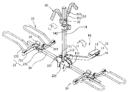
Fig. 1 is a perspective view to show the bicycle rack of the present
invention;
Fig. 2 is an exploded view to show the connection portion and the
securinc~ unit of the present invention, and the connection tube on a vehicle;
Fig. 3 shows the connection of the frame and the two side rods and the post
of the bicycle rack of the present invention;
Fig. 4 shows the wheel retaining unit movable on the side rod;
Fig. 5 shows the bicycle rack is folded;
Fig. 6 shows the frame securing unit is movable on the post;
Fig. 7 shows the bicycle is positioned on the bicycle rack, and
Fug. 8 shows that the post is pivoted to horizontal direction.
DETAILED DESCRIPTION OF THE PREFERRED EMBODIMENT
Referring to Figs. 1 to 3, the bicycle rack of the present invention comprises
a
connection portion 10 including a frame 11 on a first end thereof and a second
end
of the connection portion 10 is connected with a connection tube 50 on a
vehicle
(not shown) by a securing unit 12. The securing unit 12 includes a U-shaped
member 13 mounted to the second end of the connection portion 10 and the
connection tube 50 is mounted to the second end of the connection portion 10.
A pin
2

.,
CA 02587045 2007-05-02
14 extends through the U-shaped member 13, the connection tube 50 and the
second end of the connection portion 10 so as to connect the bicycle rack to
the
vehicle.
The frame 11 includes two side recesses 111 on two sides thereof and a top
recess '112 is defined in a top of the frame 11. Each of the two side recesses
111 is
composed of two sidewalls and two side rods 21 are pivotably connected to the
two
side recesses 111 of the frame 11 by a positioning arrangement 22. Two wheel
securing devices 20 are connected to the two side rods 21 respectively and
each
wheel securing device 20 includes a wheel retaining units 23 which has a U-
shaped
member 233. The positioning arrangement 22 includes a first hole 222 and a
second
hole 223 defined in each of the sidewalls, and each of the two side rods 21
includes
two posiitioning holes 221. One of the two positioning holes 221 is aligned
with one
of the first and second holes 222, 223, an L-shaped pin 225 extends through
the
aligned positioning hole 221 and one of the first and second holes 222, 223.
Each of
first and second holes 222, 223 and the positioning holes 221 communicates
with
respective one of notches 224 and the pin 225 includes a protrusion 226 which
extends through the notches 224 and the pin 225 is rotated angle to move the
protrusion 226 away from the notches 224. It is noted that as shown in Fig. 3,
when
the side rods 21 are located at horizontal positions, the pin 225 extends
through the
second tioles 223 and one of the positioning holes 221. When the sides rods 21
are
pivoted upward, the pin 225 extends through the first holes 222 and one of the
positioning holes 221.
Referring to Fig. 4, the wheel retaining units 23 of each of the wheel
securing
devices 20 includes a bar 231, a locking set 232 connected to an end of the
bar 231
and the U-shaped member 233 extending from the bar 231. The locking set 232 is
cooperated with a locking assembly 24 which includes two clamping members so
as
to clamp the side rod 21 therebetween and a threaded rod 241 extend through
the
two clamping members. A knob 242 is threadedly connected to the threaded rod
241 to secure the locking set 232 at desired position on the side rod 21.
Therefore, the U-shaped member 233 is movable on the side rod 21 to adjust the
distance between the two U-shaped members 233 on the two side rods 21 to fit
bicycles of different sizes. A securing belt 243 is mounted to the bar 231 to
further tie
the bicycle wheel.
A post 31 is pivotably engaged with the top recess 112 which is composed of
two sidewalls and a positioning hole 321 is defined through each of the two
sidewalls. An L-shaped pin 323 extends through the positioning holes 321 and
the
3

I I I N II CA 02587045 2007-05-02
post 31. Each of the positioning hole 321 communicates with a notch 322 and
the
pin 323 includes a protrusion (not shown) which extends through the notches
322
and the pin 323 is rotated angle to move the protrusion away from the notches
322.
A frame securing unit 30 is connected to the post 31 and includes a securing
member 33 which is movably connected to the post 31. A locking set 32 is
movably
mounted to the post 31 and a securing member 33 is connected to the locking
set
32. The securing member 33 includes a rod 331 and a hook 333. The locking set
32
is cooperated with a positioning set 34 which includes a threaded rod 341
extending through two clamping members of the locking set 32 and a knob 342 is
threadedly connected to the threaded rod 341. The hook 333 is lowered to hook
on
the bicycle frame to further position the bicycle as shown in Figs. 6 and 7.
Accordingly, the bicycle can be well secured on the bicycle rack and the
wheels of the bicycle are positioned in the U-shaped members 233. The hook 333
applies a downward force to set the bicycle on the bicycle rack.
As shown in Fig. 5, when the bicycle rack is not in use, the two side rods 21
can be pivoted upward so that the bicycle rack is compact and easily to be
stored.
As shown in Fig. 8, another way to store the bicycle rack is simply pivoting
the post
31 to horizontal position and the whole bicycle rack is flat and can be stored
in the
vehicle trunk without occupying too much space.
While we have shown and described the embodiment in accordance with the
present unvention, it should be clear to those skilled in the art that further
embodiments may be made without departing from the scope of the present
invention.
4

Representative Drawing
A single figure which represents the drawing illustrating the invention.
Administrative Status

2024-08-01:As part of the Next Generation Patents (NGP) transition, the Canadian Patents Database (CPD) now contains a more detailed Event History, which replicates the Event Log of our new back-office solution.

Please note that "Inactive:" events refers to events no longer in use in our new back-office solution.

For a clearer understanding of the status of the application/patent presented on this page, the site Disclaimer , as well as the definitions for Patent , Event History , Maintenance Fee  and Payment History  should be consulted.

Event History

Description Date
Time Limit for Reversal Expired 2010-05-03
Application Not Reinstated by Deadline 2010-05-03
Deemed Abandoned - Failure to Respond to Maintenance Fee Notice 2009-05-04
Application Published (Open to Public Inspection) 2007-11-02
Inactive: Cover page published 2007-11-01
Inactive: First IPC assigned 2007-10-12
Inactive: IPC assigned 2007-10-12
Inactive: IPC assigned 2007-08-08
Application Received - Regular National 2007-05-30
Inactive: Filing certificate - No RFE (English) 2007-05-30

Abandonment History

Abandonment Date Reason Reinstatement Date
2009-05-04

Fee History

Fee Type Anniversary Year Due Date Paid Date
Application fee - small 2007-05-02
Owners on Record

Note: Records showing the ownership history in alphabetical order.

Current Owners on Record
CHIU-KUEI WANG
Past Owners on Record
None
Past Owners that do not appear in the "Owners on Record" listing will appear in other documentation within the application.
Documents

To view selected files, please enter reCAPTCHA code :


To view images, click a link in the Document Description column. To download the documents, select one or more checkboxes in the first column and then click the "Download Selected in PDF format (Zip Archive)" or the "Download Selected as Single PDF" button.

List of published and non-published patent-specific documents on the CPD .

If you have any difficulty accessing content, you can call the Client Service Centre at 1-866-997-1936 or send them an e-mail at CIPO Client Service Centre.


Document
Description 
Date
(yyyy-mm-dd) 
Number of pages   Size of Image (KB) 
Abstract 2007-05-01 1 13
Description 2007-05-01 4 197
Drawings 2007-05-01 8 166
Claims 2007-05-01 2 101
Representative drawing 2007-10-08 1 15
Filing Certificate (English) 2007-05-29 1 159
Reminder of maintenance fee due 2009-01-04 1 113
Courtesy - Abandonment Letter (Maintenance Fee) 2009-06-28 1 172