Language selection

Search

Patent 2587333 Summary

Third-party information liability

Some of the information on this Web page has been provided by external sources. The Government of Canada is not responsible for the accuracy, reliability or currency of the information supplied by external sources. Users wishing to rely upon this information should consult directly with the source of the information. Content provided by external sources is not subject to official languages, privacy and accessibility requirements.

Claims and Abstract availability

Any discrepancies in the text and image of the Claims and Abstract are due to differing posting times. Text of the Claims and Abstract are posted:

  • At the time the application is open to public inspection;
  • At the time of issue of the patent (grant).
(12) Patent Application: (11) CA 2587333
(54) English Title: LIQUID SPECIMEN SAMPLING SYSTEM AND METHOD
(54) French Title: SYSTEME DE PRELEVEMENT D'ECHANTILLONS LIQUIDES, ET PROCEDE ASSOCIE
Status: Deemed Abandoned and Beyond the Period of Reinstatement - Pending Response to Notice of Disregarded Communication
Bibliographic Data
(51) International Patent Classification (IPC):
  • A61B 05/00 (2006.01)
(72) Inventors :
  • PRESSMAN, NORMAN J. (United States of America)
  • MAYER, WILLIAM J. (United States of America)
(73) Owners :
  • MONOGEN, INC.
(71) Applicants :
  • MONOGEN, INC. (United States of America)
(74) Agent: BERESKIN & PARR LLP/S.E.N.C.R.L.,S.R.L.
(74) Associate agent:
(45) Issued:
(86) PCT Filing Date: 2005-11-10
(87) Open to Public Inspection: 2006-05-18
Examination requested: 2008-02-22
Availability of licence: N/A
Dedicated to the Public: N/A
(25) Language of filing: English

Patent Cooperation Treaty (PCT): Yes
(86) PCT Filing Number: PCT/US2005/040764
(87) International Publication Number: US2005040764
(85) National Entry: 2007-05-10

(30) Application Priority Data:
Application No. Country/Territory Date
60/626,441 (United States of America) 2004-11-10

Abstracts

English Abstract


Method and system for obtaining a liquid sample from a particulate matter-
containing liquid in, e.g., a specimen container. A receptacle is used that
has an inlet and a chamber for collecting the liquid sample. A discharge
passage accommodates upward flow of liquid from the container. The discharge
passage preferably has an upper discharge port, and at least one intake
submerged in the liquid in the container. A flow-metering passage prevents
particulate matter above a predetermined size from passing into the receptacle
chamber. Liquid transfer commences after the receptacle inlet is placed in
liquid-tight communication with the discharge port. Operation of mechanized
system also is disclosed, as well as an arrangement and method for handling
multiple receptacles at a liquid transfer station.


French Abstract

L'invention porte sur un procédé et un système de prélèvement d'échantillons liquides dans un liquide contenant une matière particulaire, se trouvant par exemple dans un conteneur renfermant une préparation. On utilise un réceptacle présentant un orifice d'entrée et une chambre de recueil de l'échantillon liquide. Un passage qui reçoit le liquide montant du conteneur présente de préférence un orifice supérieur de décharge et au moins une prise noyée dans le liquide du conteneur. Un calibre empêche les particules dépassant une taille prédéterminée de passer dans la chambre du réceptacle. Le transfert du liquide commence lorsque l'orifice d'entrée du réceptacle se trouve en communication étanche avec l'orifice de décharge. L'invention porte également sur le fonctionnement d'un système mécanisé, et sur un appareil et le procédé associé de manipulation de multiples réceptacles dans une station de transfert de liquides.

Claims

Note: Claims are shown in the official language in which they were submitted.


CLAIMS
1. A method for obtaining a liquid sample from a particulate matter-containing
liquid
specimen in a container, the liquid sample containing size-restricted
particulate matter, the
method comprising the steps of:
providing a receptacle having a chamber for collecting the liquid sample, the
receptacle having an inlet;
providing a discharge passage through which liquid can flow upwardly from the
container to the receptacle, the discharge passage having an upper discharge
port and at least
one intake submerged in the liquid in the container;
providing at least one flow-metering passage associated with the discharge
passage or
the receptacle, the flow-metering passage preventing particulate matter above
a
predetermined size from passing into the receptacle chamber;
placing the receptacle inlet in liquid-tight communication with the discharge
port; and
causing particulate matter-containing liquid to flow from the container
upwardly
through the discharge passage, through the receptacle inlet and into the
receptacle chamber,
the flowing liquid also passing through the flow-metering passage so that the
liquid sample
collected in the receptacle contains only size-restricted particulate matter.
2. A method according to claim 1, wherein the step of causing particulate
matter-
containing liquid to flow from the container to the receptacle chamber
comprises creating a
pressure differential across the receptacle inlet such that the pressure in
the receptacle
chamber is less than the pressure in the container.
3. A method according to claim 2, wherein the step of creating a pressure
differential
comprises applying a vacuum to the receptacle chamber.
4. A method according to claim 2, wherein the inlet is in a resilient tip on
the receptacle,
the resilient tip is adapted to fit into and form a seal with the discharge
port, and the resilient
tip comprises a one-way valve that is pressure-actuated to permit fluid flow
into the interior
of the receptacle when the pressure in the receptacle is less than the
pressure outside the
receptacle at the inlet, and prevents outflow of fluid from the receptacle
under the influence
of any other relative pressure conditions; and wherein the step of placing the
receptacle in
liquid-tight communication with the discharge port comprises inserting the
resilient tip into
the discharge port to form a seal with the discharge port.
13

5. A method according to claim 1, wherein the discharge passage comprises the
lumen
of a tube, and the tube has a vent hole in communication with the lumen of the
tube below
and close to the discharge port; and wherein the step of placing the
receptacle in liquid-tight
communication with the discharge port comprises inserting the portion of the
receptacle
having the inlet into the discharge port to form a seal with the discharge
port and to seal off
the vent hole.
6. A method according to claim 5, wherein the inlet is in a resilient tip on
the receptacle
and the resilient tip comprises a one-way valve that is pressure-actuated to
permit fluid flow
into the interior of the receptacle when the pressure in the receptacle is
less than the pressure
outside the receptacle at the inlet, and prevents outflow of fluid from the
receptacle under the
influence of any other relative pressure conditions; and wherein the step of
placing the
receptacle in liquid-tight communication with the discharge port comprises
inserting the
resilient tip into the discharge port to form a seal with the discharge port
and to seal off the
vent hole.
7. A method according to claim 6, wherein the step of causing specimen liquid
to flow
upwardly through the discharge passage and into the receptacle inlet comprises
creating a
pressure differential across the receptacle inlet such that the pressure in
the receptacle is less
than the pressure in the container.
8. A system for obtaining a liquid sample from a particulate matter-containing
liquid
specimen in a container, the liquid sample containing size-restricted
particulate matter, the
system comprising:
a receptacle having a chamber for collecting the liquid sample, the receptacle
having
an inlet;
a discharge element associated with the container and through which liquid can
flow
upwardly from the container to the receptacle, the discharge element having a
discharge
passage with an upper discharge port and at least one intake submerged in the
liquid in the
container; and
at least one flow-metering passage associated with the discharge passage or
the
receptacle, the flow-metering passage preventing particulate matter above a
predetermined
size from passing into the receptacle chamber so that the liquid sample
collected in the
receptacle chamber contains only size-restricted particulate matter;
14

wherein the receptacle inlet and the discharge port are adapted to releasably
and
sealingly mate to allow specimen liquid to flow from the container to the
receptacle chamber.
9. A system according to claim 8, wherein the inlet is in a resilient tip on
the receptacle,
and the resilient tip is adapted to fit into and form a seal with the
discharge port.
10. A system according to claim 9, wherein the resilient tip comprises a one-
way valve
that is pressure-actuated to permit fluid flow into the interior of the
receptacle when the
pressure in the receptacle is less than the pressure outside the receptacle at
the inlet, and
prevents outflow of fluid from the receptacle under the influence of any other
relative
pressure conditions.
11. A system according to claim 8, wherein the discharge element comprises a
tube, the
discharge passage comprises the lumen of the tube, and the tube has a vent
hole in
communication with the lumen of the tube below and close to the discharge
port; and wherein
the portion of the receptacle having the inlet is adapted to fit into and form
a seal with the
discharge port, and seal off the vent hole.
12. A system according to claim 11, wherein the inlet is in a resilient tip on
the receptacle,
and the resilient tip is adapted to fit into and form a seal with the
discharge port, and seal off
the vent hole.
13. A system according to claim 12, wherein the resilient tip comprises a one-
way valve
that is pressure-actuated to permit fluid flow into the interior of the
receptacle when the
pressure in the receptacle is less than the pressure outside the receptacle at
the inlet, and
prevents outflow of fluid from the receptacle under the influence of any other
relative
pressure conditions.
14. A method for obtaining a liquid sample from a particulate matter-
containing liquid
specimen in a container, the liquid sample containing size-restricted
particulate matter, the
method comprising the steps of:
providing a receptacle for collecting the liquid sample, the receptacle having
an inlet;
providing a discharge passage through which liquid can flow upwardly from the
container to the receptacle, the discharge passage having an upper discharge
port and at least
15

one flow-metering intake submerged in the liquid in the container and through
which liquid
containing only size-restricted particulate matter can enter the discharge
passage;
placing the receptacle inlet in liquid-tight communication with the discharge
port; and
causing liquid containing size-restricted particulate matter to flow upwardly
through
the discharge passage and into the receptacle.
15. A method according to claim 14, wherein the at least one flow-metering
intake is
disposed at or near the bottom of the container so that the liquid sample is
drawn from the
bottom of the specimen.
16. A method according to claim 14, wherein the discharge passage has a
plurality of
flow-metering intakes.
17. A method according to claim 16, wherein the flow-metering intakes are
disposed at or
near the bottom of the container so that the liquid sample is drawn from the
bottom of the
specimen.
18. A method according to any one of claims 14 through 17, wherein the step of
causing
liquid containing size-restricted particulate matter to flow upwardly through
the discharge
passage and into the receptacle comprises creating a pressure differential
across the
receptacle inlet such that the pressure in the receptacle is less than the
pressure in the
container.
19. A method according to claim 18, wherein the step of creating a pressure
differential
comprises applying a vacuum to the receptacle.
20. A method according to claim 18, wherein the inlet is in a resilient tip on
the
receptacle, the resilient tip is adapted to fit into and form a seal with the
discharge port, and
the resilient tip comprises a one-way valve that is pressure-actuated to
permit fluid flow into
the interior of the receptacle when the pressure in the receptacle is less
than the pressure
outside the receptacle at the inlet, and prevents outflow of fluid from the
receptacle under the
influence of any other relative pressure conditions; and wherein the step of
placing the
receptacle in liquid-tight communication with the discharge port comprises
inserting the
resilient tip into the discharge port to form a seal with the discharge port.
16

21. A method according to claim 14, wherein the discharge passage comprises
the lumen
of a tube, and the tube has a vent hole in communication with the lumen of the
tube below
and close to the discharge port; and wherein the step of placing the
receptacle in liquid-tight
communication with the discharge port comprises inserting the portion of the
receptacle
having the inlet into the discharge port to form a seal with the discharge
port and to seal off
the vent hole.
22. A method according to claim 21, wherein the inlet is in a resilient tip on
the receptacle
and the resilient tip comprises a one-way valve that is pressure-actuated to
permit fluid flow
into the interior of the receptacle when the pressure in the receptacle is
less than the pressure
outside the receptacle at the inlet, and prevents outflow of fluid from the
receptacle under the
influence of any other relative pressure conditions; and wherein the step of
placing the
receptacle in liquid-tight communication with the discharge port comprises
inserting the
resilient tip into the discharge port to form a seal with the discharge port
and to seal off the
vent hole.
23. A method according to claim 22, wherein the step of causing liquid
containing size-
restricted particulate matter to flow upwardly through the discharge passage
and into the
receptacle comprises creating a pressure differential across the receptacle
inlet such that the
pressure in the receptacle is less than the pressure in the container.
24. A system for obtaining a liquid sample from a particulate matter-
containing liquid
specimen in a container, the liquid sample containing size-restricted
particulate matter, the
system comprising:
a receptacle for collecting the liquid sample, the receptacle having an inlet;
and
a discharge element associated with the container and through which liquid can
flow
upwardly from the container to the receptacle, the discharge element having a
discharge
passage with an upper discharge port and at least one flow-metering intake
submerged in the
liquid in the container and through which liquid containing only size-
restricted particulate
matter can enter the discharge passage;
wherein the receptacle inlet and the discharge port are adapted to releasably
and
sealingly mate to allow sample liquid to flow into the receptacle.
25. A system according to claim 24, wherein the discharge element has a
plurality of
flow-metering intakes.
17

26. A system according to claim 25, wherein the flow-metering intakes are
disposed at or
near the bottom of the container.
27. A system according to claim 26, wherein the discharge element comprises a
tube, the
discharge passage comprises the lumen of the tube, and the flow-metering
intakes are located
around the periphery of the tube at or immediately adjacent the bottom end of
the tube.
28. A system according to claim 27, wherein the bottom end of the tube is
open, and the
bottom end of the tube and the bottom wall of the container are configured to
form a plurality
of discrete contact areas at their interface and a plurality of discrete flow-
metering intakes
between the contact areas.
29. A system according to claim 28, wherein at least one of the bottom end of
the tube
and the bottom wall of the container has a plurality of standoffs contacting
the other.
30. A system according to claim 29, wherein the standoffs comprise
peripherally spaced
feet on the bottom end of the tube that contact the bottom wall of the
container.
31. A system according to claim 30, wherein the bottom end of the tube is
flared
outwardly.
32. A system according to claim 27, wherein the tube has a vent hole in
communication
with the lumen of the tube below and close to the discharge port, and the
portion of the
receptacle having the inlet is adapted to fit into and form a seal with the
discharge port, and
seal off the vent hole.
33. A system according to claim 32, wherein the inlet is in a resilient tip on
the receptacle,
and the resilient tip is adapted to fit into and form a seal with the
discharge port, and seal off
the vent hole.
34. A system according to claim 33, wherein the resilient tip comprises a one-
way valve
that is pressure-actuated to permit fluid flow into the interior of the
receptacle when the
pressure in the receptacle is less than the pressure outside the receptacle at
the inlet, and
prevents outflow of fluid from the receptacle under the influence of any other
relative
pressure conditions.
18

35. A system according to any one of claims 24 through 27, wherein the inlet
is in a
resilient tip on the receptacle, and the resilient tip is adapted to fit into
and form a seal with
the discharge port.
36. A system according to claim 35, wherein the resilient tip comprises a one-
way valve
that is pressure-actuated to permit fluid flow into the interior of the
receptacle when the
pressure in the receptacle is less than the pressure outside the receptacle at
the inlet, and
prevents outflow of fluid from the receptacle under the influence of any other
relative
pressure conditions.
37. A system according to claim 24, wherein the discharge element comprises a
tube, the
discharge passage comprises the lumen of the tube, and the tube has a vent
hole in
communication with the lumen of the tube below and close to the discharge
port; and wherein
the portion of the receptacle having the inlet is adapted to fit into and form
a seal with the
discharge port, and seal off the vent hole.
38. A system according to claim 37, wherein the inlet is in a resilient tip on
the receptacle,
and the resilient tip is adapted to fit into and form a seal with the
discharge port, and seal off
the vent hole.
39. A system according to claim 38, wherein the resilient tip comprises a one-
way valve
that is pressure-actuated to permit fluid flow into the interior of the
receptacle when the
pressure in the receptacle is less than the pressure outside the receptacle at
the inlet, and
prevents outflow of fluid from the receptacle under the influence of any other
relative
pressure conditions.
40. A method for obtaining a liquid sample from a particulate matter-
containing liquid
specimen in a container, the liquid sample containing size-restricted
particulate matter, the
method comprising the steps of:
providing a receptacle for collecting the liquid sample, the receptacle having
an inlet
and at least one flow-metering passage which prevents passage of particulate
matter above a
predetermined size;
providing a discharge passage through which liquid can flow upwardly from the
container to the receptacle, the discharge passage having an upper discharge
port and at least
one intake submerged in the liquid in the container;
19

placing the receptacle inlet in liquid-tight communication with the discharge
port; and
causing specimen liquid to flow upwardly through the discharge passage and
through
the receptacle inlet to the flow-metering passage, which prevents passage of
particulate
matter above a predetermined size, whereby the liquid sample collected in the
receptacle
contains only size-restricted particulate matter.
41. A method according to claim 40, wherein the step of causing specimen
liquid to flow
upwardly through the discharge passage and into the receptacle inlet comprises
creating a
pressure differential across the receptacle inlet such that the pressure in
the receptacle is less
than the pressure in the container.
42. A method according to claim 41, wherein the step of creating a pressure
differential
comprises applying a vacuum to the receptacle.
43. A method according to claim 41, wherein the inlet is in a resilient tip on
the
receptacle, the resilient tip is adapted to fit into and form a seal with the
discharge port, and
the resilient tip comprises a one-way valve that is pressure-actuated to
permit fluid flow into
the interior of the receptacle when the pressure in the receptacle is less
than the pressure
outside the receptacle at the inlet, and prevents outflow of fluid from the
receptacle under the
influence of any other relative pressure conditions; and wherein the step of
placing the
receptacle in liquid-tight communication with the discharge port comprises
inserting the
resilient tip into the discharge port to form a seal with the discharge port.
44. A method according to claim 40, wherein the discharge passage comprises
the lumen
of a tube, and the tube has a vent hole in communication with the lumen of the
tube below
and close to the discharge port; and wherein the step of placing the
receptacle in liquid-tight
communication with the discharge port comprises inserting the portion of the
receptacle
having the inlet into the discharge port to form a seal with the discharge
port and to seal off
the vent hole.
45. A method according to claim 44, wherein the inlet is in a resilient tip on
the receptacle
and the resilient tip comprises a one-way valve that is pressure-actuated to
permit fluid flow
into the interior of the receptacle when the pressure in the receptacle is
less than the pressure
outside the receptacle at the inlet, and prevents outflow of fluid from the
receptacle under the
influence of any other relative pressure conditions; and wherein the step of
placing the
20

receptacle in liquid-tight communication with the discharge port comprises
inserting the
resilient tip into the discharge port to form a seal with the discharge port
and to seal off the
vent hole.
46. A method according to claim 45, wherein the step of causing specimen
liquid to flow
upwardly through the discharge passage and into the receptacle inlet comprises
creating a
pressure differential across the receptacle inlet such that the pressure in
the receptacle is less
than the pressure in the container.
47. A system for obtaining a liquid sample from a particulate matter-
containing liquid
specimen in a container, the liquid sample containing size-restricted
particulate matter, the
system comprising:
a receptacle for collecting the liquid sample, the receptacle having an inlet
and at least
one flow-metering passage which prevents passage of particulate matter above a
predetermined size so that the liquid sample collected in the receptacle
contains only size-
restricted particulate matter; and
a discharge element associated with the container and through which liquid can
flow
upwardly from the container to the receptacle, the discharge element having a
discharge
passage with an upper discharge port and at least one intake submerged in the
liquid in the
container;
wherein the receptacle inlet and the discharge port are adapted to releasably
and
sealingly mate to allow specimen liquid to flow from the container to the
receptacle.
48. A system according to claim 47, wherein the flow-metering passage
comprises a
filter.
49. A system according to claim 47, wherein the inlet is in a resilient tip on
the receptacle,
and the resilient tip is adapted to fit into and form a seal with the
discharge port.
50. A system according to claim 49, wherein the resilient tip comprises a one-
way valve
that is pressure-actuated to permit fluid flow into the interior of the
receptacle when the
pressure in the receptacle is less than the pressure outside the receptacle at
the inlet, and
prevents outflow of fluid from the receptacle under the influence of any other
relative
pressure conditions.
21

51. A system according to claim 47, wherein the discharge element comprises a
tube, the
discharge passage comprises the lumen of the tube, and the tube has a vent
hole in
communication with the lumen of the tube below and close to the discharge
port; and wherein
the portion of the receptacle having the inlet is adapted to fit into and form
a seal with the
discharge port, and seal off the vent hole.
52. A system according to claim 51, wherein the inlet is in a resilient tip on
the receptacle,
and the resilient tip is adapted to fit into and form a seal with the
discharge port, and seal off
the vent hole.
53. A system according to claim 52, wherein the resilient tip comprises a one-
way valve
that is pressure-actuated to permit fluid flow into the interior of the
receptacle when the
pressure in the receptacle is less than the pressure outside the receptacle at
the inlet, and
prevents outflow of fluid from the receptacle under the influence of any other
relative
pressure conditions.
54. A method for optionally obtaining a liquid sample and/or a particulate
matter sample
from a particulate matter-containing liquid specimen in a container, the
method using an
apparatus comprising a liquid sampling station for collecting a liquid sample
in a receptacle
having a resilient tip with an inlet, and a specimen acquisition station
having an aspiration
head for collecting a sample layer of particulate matter separated from the
liquid on a surface
of a filter, the container having therein a processing assembly comprising an
upper separation
chamber adapted to receive a filter and a tube extending downwardly from the
separation
chamber into the specimen liquid in the container, the tube having a vent hole
above the level
of specimen liquid in the container, the method comprising optionally
performing one or both
of the following series of steps (a) and/or (b) in either order:
(a) inserting the resilient tip of the receptacle into the upper end of the
tube to form a
seal with the upper end of the tube and seal off the vent hole, and applying a
vacuum to the
receptacle to withdraw liquid from the container through the inlet and into
the receptacle;
(b) placing a filter in the separation chamber, sealing the aspiration head to
the upper
portion of the separation chamber, and applying a vacuum to aspirate liquid
from the
container through the tube and aspirate air into the tube through the vent
hole, whereby
particulate matter is separated from the aspirated liquid, and a sample layer
of particulate
matter is formed on a surface of the filter.
22

55. A method according to claim 54, wherein the apparatus places the sample
layer of
particulate matter on a slide.
56. A method according to claim 54 or claim 55, wherein the specimen is a
biological
specimen.
57. A method according to claim 54, wherein series of steps (a) and (b) are
performed.
58. A method according to claim 57, wherein series of steps (a) are performed
before
series of steps (b).
59. A method according to claim 57 or claim 58, wherein the apparatus places
the sample
layer of particulate matter on a slide.
60. A method according to claim 59, wherein the specimen is a biological
specimen.
61. A method for handling receptacles at a liquid sampling station at which
liquid can be
transferred to the receptacles, each receptacle having a bottom inlet adapted
to dock with an
upwardly facing port through which liquid can flow, the method comprising the
steps of:
providing at least one carrier removably holding a plurality of receptacles;
advancing the carrier along a path that extends toward and away from a liquid
transfer
location;
removing one receptacle at a time from the carrier, and for each receptacle
removed:
moving the receptacle so as to dock the inlet of the receptacle with the port;
moving the receptacle so as to undock the inlet from the port; and
returning the receptacle to the carrier.
62. A method according to claim 61, wherein the receptacle removing and
returning steps
comprise lifting and lowering the receptacle out of and into the carrier,
respectively.
63. A method according to claim 61, wherein the receptacle docking and
undocking steps
comprise lowering and lifting the receptacle toward and away from the port,
respectively.
64. A method according to claim 61, wherein the advancing step comprises
advancing the
carrier stepwise one receptacle at a time.
23

65. A method according to claim 64, wherein the carrier is arrested when a
receptacle is
to be removed from or returned to the carrier.
66. A method according to claim 61, wherein a plurality of carriers are moved
along the
processing path seriatim.
67. An apparatus for handling receptacles at a liquid sampling station at
which liquid can
be transferred to the receptacles, each receptacle having a bottom inlet
adapted to dock with
an upwardly facing port through which liquid can flow, the apparatus
comprising:
at least one carrier having a plurality of receptacle locators adapted to
removably hold
a like number of receptacles;
at least one guide member defining a path of movement for the carrier toward
and
away from a liquid transfer location;
a carrier-advancing mechanism for moving the carrier along the path;
a gripper releasably engageable with each receptacle in the carrier, and
a multi-axis gripper drive mechanism adapted to move the gripper so that it
can
remove a receptacle from the carrier, dock the inlet of the receptacle with
the port, and return
the receptacle to the carrier.
68. An apparatus according to claim 67, wherein the gripper drive mechanism is
adapted
to lift and lower the gripper so as to enable the receptacle to be lifted from
and lowered back
into its locator in the carrier, as well as to enable the receptacle inlet to
be docked with and
undocked from the port.
69. An apparatus according to claim 68, wherein each receptacle locator
comprises a
sleeve that slidably receives a receptacle.
70. An apparatus according to claim 69, wherein each sleeve has a window
through which
the receptacle can be viewed.
71. An apparatus according to claim 67, wherein the carrier advancing
mechanism is
adapted to advance the carrier stepwise, one receptacle at a time.
72. An apparatus according to claim 71, wherein the carrier advancing
mechanism is
synchronized with the gripper drive mechanism such that the carrier is
arrested when the
gripper is engaged with a receptacle.
24

73. An apparatus according to claim 67, comprising a feeder tray adjacent the
beginning
of the path for holding a plurality of carriers with receptacles, and a
receiver tray adjacent the
end of the path for holding carriers with receptacles that have been presented
to the liquid
sampling station, the carrier-advancing mechanism adapted to move carriers
from the feeder
tray along the path to the receiver tray.
25

Description

Note: Descriptions are shown in the official language in which they were submitted.


CA 02587333 2007-05-10
WO 2006/053136 PCT/US2005/040764
LIQUID SPECIMEN SAMPLING SYSTEM AND METHOD
CROSS-REFERENCE TO RELATED APPLICATIONS
This application claims the benefit of U.S. provisional application No.
60/626,441,
filed November 10, 2004. This application also is a continuation-in-part of
international
application No. PCT/USO4/37249, filed November 9, 2004; and is a continuation-
in-part of
U.S. application No. 10/274,381, filed October 21, 2002 (US 2003/0087443 Al).
These three
applications are incorporated herein by reference.
TECHNICAL FIELD
The present invention is directed to the collection and processing of liquid
specimens
for subsequent testing or analysis, e.g., biological fluid specimens, such as
used in cytology '
or molecular diagnostic protocols, or non-biological specimens, such as
drinking water
containing impurities.
BACKGROUND
US 2003/0087443 Al discloses an example of an automated (computer-controlled)
apparatus for handling specimen vials. The apparatus may be referred to as an
"LBP"
processor (for liquid-based preparation), and can be integrated into a
complete automated
laboratory system.
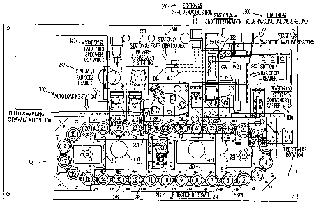
Fig. 1(a schematic top plan view) shows the overall arrangement of the
automated
processor disclosed in US 2003/0087443 Al. The LBP processor transports
multiple
specimen vials sequentially through various processing stations and produces
fixed
specimens on slides, each slide being bar-coded and linked through a data
management
system (DMS) to the vial and the patient from which it came. In the preferred
arrangement,
each vial has a special internal processing assembly detachably coupled to its
cover, and is
transported through the LBP processor on a computer-controlled transport
(conveyor) 240, in
its own receptacle 246. (In the example shown the conveyor has thirty
receptacles.) The
containers and the receptacles are keyed so that the containers proceed along
the processing
path in the proper orientation, and cannot rotate independently of their
respective receptacles.
The containers first pass a bar code reader 230 (at a data acquisition
station), where
the vial bar code is read, and then proceed stepwise through the following
processing stations
of the LBP processor: an uncapping station 400 including a cap disposal
operation; a
preprocessing station 500; a filter loading station 600; a specimen
acquisition and filter
disposal station 700; and a re-capping station 800. These six stations are
structured for
parallel processing, meaning that all of these stations can operate
simultaneously on different

CA 02587333 2007-05-10
WO 2006/053136 PCT/US2005/040764
specimens in their respective containers, and independently of the other. The
conveyor will
not advance until all of these operating stations have completed their
respective tasks.
The preprocessing station is the location at which preprocessing operations,
such as
specimen dispersal within its container, are performed prior to the container
and its specimen
moving on for further handling. The preprocessing station typically performs a
dispersal
operation. In the preferred embodiment, the dispersal operation is performed
by a
mechanical mixer (stirrer), which rotates at a fixed speed and for a fixed
duration within the
specimen container. The mixer serves to disperse large particulates and
microscopic
particulates, such as human cells, within the liquid-based specimen by
homogenizing the
specimen. Alternatively, the specimen may contain subcellular sized objects
such as
molecules in crystalline or other conformational forms. In that case, a
chemical agent may be
introduced to the specimen at the preprocessing station to, for example,
dissolve certain
crystalline structures and allow the molecules to be dispersed throughout the
liquid-based
specimen through chemical diffusion processes without the need for mechanical
agitation.
Such a chemical preprocessing station introduces its dispersing agent through
the
preprocessing head.
There is also an integrated system 900 that includes additional bar code
readers, slide
cassettes, handling mechanisms for slide cassettes and individual slides, and
a slide
presentation station 702 at which the specimen acquisition station transfers a
representative
sample from a specimen to a fresh microscope slide. An optional auto loading
mechanism
300 automatically loads and unloads specimen vials onto and from the transport
mechanism.
All stations and mechanisms are computer-controlled.
In the preferred embodiment of this LBP processor, the vial uncapping station
400 has
a rotary gripper that unscrews the cover from the vial, and discards it into a
biosafety
disposable waste handling bag. Before discarding the cover, however, the
uncapping head
presses on the center of the cover as described above to detach the internal
processing
assembly (stirrer) from the cover. The preprocessing (mixing) station 500 has
an expanding
collet that grips the processing assembly, lifts it slightly and moves (e.g.,
spins) it in
accordance with a specimen-specific stirring protocol (speed and duration).
The filter
loading station 600 dispenses a specimen-specific filter type into a
particulate matter
separation chamber (manifold) at the top of the processing assembly. The
specimen
acquisition station 700 has a suction head that seals to the filter at the top
of the processing
assembly and first moves the processing assembly slowly to re-suspend
particulate matter in
0
2

CA 02587333 2007-05-10
WO 2006/053136 PCT/US2005/040764
the liquid-based specimen. Then the suction head draws a vacuum on the filter
to aspirate the
liquid-based specimen from the vial and past the filter, leaving a thin layer
of cells on the
bottom surface of the filter. Thereafter the thin layer specimen is
transferred to a fresh slide,
and the container moves to the re-capping station, where a foil-type seal is
applied.
The LBP processor shown in Fig. 1 also is equipped with a liquid sampling draw
station 100, which is adapted to place a specially designed liquid collection
receptacle into
engagement with the processing assembly (stirrer) present in any of the
specimen containers
processed by the LBP processor. The receptacle is in the form of a molded
plastic cuvette,
and has a thermoplastic elastomer one-way valve on one end that mates with and
seals
against the upper end of the processing assembly. The valve admits liquid into
the cuvette
when the cuvette is placed under vacuum to draw liquid from the specimen
container up
through the processing assembly. The valve is otherwise sealed to prevent the
escape of
liquid from the cuvette. A syringe or a cannula can be used to withdraw liquid
from the
cuvette for testing. Preferably the cuvette is bar-coded so that it can be
linked to the
specimen vial and the patient identifying data through the DMS.
As illustrated in Fig. 1, the liquid sampling draw station 100 is located just
after
(downstream of) the mixing station 500 of the LBP processor. However, the
liquid sampling
draw station instead could be located downstream of the specimen acquisition
station 700.
Actuation of the liquid sampling draw station 100 preferably is governed by
the particular
processing protocol for each specimen. Accordingly, there may be specimen
containers from
which no liquid sample is drawn, in which case the liquid sampling draw
station will remain
idle while such a container dwells there. It is also possible for the liquid
sampling draw
station to draw a variable liquid volume, again dependent on the particular
processing
protocol for each specimen. To accomplish that, a plurality of vertically
spaced liquid level
sensors would monitor the changing level of liquid in the receptacle, and
liquid draw would
be terminated when the specified liquid volume is acquired.
SUMMARY DISCLOSURE OF THE INVENTION
The invention disclosed in the present application concerns liquid sample
collection in
general. It also concerns a liquid sampling draw station that may be used in
an LBP
processor, and the liquid collection receptacles (cuvettes) that may be
employed at that
station. The invention further concerns operation of an LBP processor, which
may be
controlled with respect to an individual vial, depending on protocol, so as to
draw a liquid
3

CA 02587333 2007-05-10
WO 2006/053136 PCT/US2005/040764
sample from the vial at the liquid sampling draw station, and/or to draw
liquid at the
specimen acquisition station to make a slide-mounted sample, in either order.
A first aspect of the invention concerns methods and systems for obtaining a
liquid
sample containing size-restricted particulate matter from a par ticulate
matter-containing
liquid in a container. A receptacle is used that has an inlet and a chamber
for collecting the
liquid sample. A discharge passage accommodates upward flow of liquid from the
container.
The discharge passage preferably has an upper discharge port, and at least one
intake
submerged in the liquid in the container. A flow-metering passage prevents
particulate
matter above a predetermined size from passing into the receptacle chamber.
The receptacle
inlet is placed in liquid-tight communication with the discharge port, and
particulate matter-
containing liquid is caused to flow from the container upwardly through the
discharge
passage, through the receptacle inlet and into the receptacle chamber. The
flowing liquid also
passes through the flow-metering passage so that the liquid sample collected
in the receptacle
contains only size-restricted particulate matter.
The discharge passage, the discharge port and the intake may be in a discharge
element that is associated with the container, i.e., is in, is insertable
into, or is part of the
container. For example, the discharge element may be the tubular portion of a
processing
assembly that is already in the container, or a tube that is inserted into the
container just prior
to sample collection, or part of the container wall. The flow-metering passage
may be
associated with the discharge passage or the receptacle. For example, the
intake may act as
the flow-metering passage; or the flow-metering passage may be a filter in the
receptacle
located between the inlet and the chamber for collecting the liquid sample.
Another aspect of the invention concerns a method for optionally obtaining a
liquid
sample and/or a particulate matter sample from a particulate matter-containing
liquid
specimen in a container. The method uses an apparatus comprising a liquid
sampling station
for collecting a liquid sample in a receptacle having a resilient tip with an
inlet, and a
specimen acquisition station having an aspiration head for collecting a sample
layer of
particulate matter separated from the liquid on a surface of a filter. The
container has therein
a processing assembly comprising an upper separation chamber adapted to
receive a filter and
a tube extending downwardly from the separation chamber into the specimen
liquid in the
container. The tube has a vent hole above the level of specimen liquid in the
container. The
method involves optionally performing one or both of the following series of
steps (a) and/or
(b) in either order:
4

CA 02587333 2007-05-10
WO 2006/053136 PCT/US2005/040764
(a) inserting the resilient tip of the receptacle into the upper end of the
tube to form a
seal with the upper end of the tube and seal off the vent hole, and applying a
vacuum to the
receptacle to withdraw liquid from the container through the inlet and into
the receptacle;
(b) placing a filter in the separation chamber, sealing the aspiration head to
the upper
portion of the separation chamber, and applying a vacuum to aspirate liquid
from the
container through the tube and aspirate air into the tube through the vent
hole, whereby
particulate matter is separated from the aspirated liquid, and a sample layer
of particulate
matter is formed on a surface of the filter.
A further aspect of the invention concerns a method and apparatus for handling
receptacles at a liquid sampling station. Each receptacle has a bottom inlet
adapted to dock
with an upwardly facing port through which liquid can flow. At least one
carrier is used to
removably hold a plurality of receptacles. The carrier is advanced along a
path that extends
toward and away from a liquid transfer location. One receptacle at a time is
removed from
the carrier. The removed receptacle is moved so as to dock the inlet of the
receptacle with
the port. Then the receptacle is moved so as to undock the inlet from the
port, and the
receptacle is returned to the carrier.
BRIEF DESCRIPTION OF THE DRAWING FIGURES
Embodiments that incorporate the best mode for carrying out the invention are
described in detail below, purely by way of example, with reference to the
accompanying
drawing, in which:
Fig. 1 is a schematic top plan view of an automated specimen processing
apparatus
with which the present invention can be used;
Fig. 2 is an elevational view of a cuvette according to the invention;
Fig. 3 is a longitudinal sectional view of the cuvette of Fig. 2;
Fig. 4 is a vertical sectional view through a specimen container and the
cuvette of Fig.
2 engaged with the processing assembly;
Fig. 5 is a detail view of a portion of the container, processing assembly and
cuvette
shown in Fig. 4;
Fig. 6 is a perspective view of the cuvette engaged with the processing
assembly of a
specimen container (shown cradled in a receptacle of the LBP processor) and
showing a
portion of a cuvette docking mechanism according to the invention;
Fig. 7 is a perspective view of the processing assembly;
Fig. 8 is a bottom plan view of the processing assembly;
5

CA 02587333 2007-05-10
WO 2006/053136 PCT/US2005/040764
Fig. 9 is an exploded vertical sectional view of the processing assembly and a
filter
assembly adapted for use in the processing assembly;
Fig. 10 is a top plan view of the center portion of the bottom wall of the
container
according to another embodiment of the invention;
Fig. 11 is an elevational view of the lower portion of the processing assembly
according to another embodiment of the invention;
Fig. 12 is a vertical sectional view of the lower portion of the processing
assembly in
a container taken along line 12-12 in Fig. 8;
Fig. 13 is a perspective view of the liquid sampling draw station according to
the
invention;
Fig. 14 is a perspective view of an LBP processor generally of the type shown
in Fig.
1, and incorporating the liquid sampling draw station of Fig. 13;
Fig. 15 is a front elevational view of the LBP processor of Fig. 14;
Fig. 16 is a close-up perspective view of a portion of the LBP processor of
Fig. 14;
Fig. 17 is a perspective view of the cuvette docking mechanism;
Fig. 18 is a top plan view of the cuvette docking mechanism of Fig. 17;
Fig. 19 is a perspective view of a clip according to the invention holding ten
cuvettes
for transport to and from the docking mechanism;
Fig. 20 is a perspective view of a transport mechanism according to the
invention for
transporting cuvettes to and from the docking mechanism;
Fig. 21 is a perspective view of the feeder tray for housing fresh (empty)
cuvettes; and
Fig. 22 is a perspective view of the receiver tray for housing used (filled)
cuvettes.
It is to be understood that the invention is not limited in its application to
the details of
construction and the arrangement of components of the preferred embodiments
described
below and illustrated in the drawing figures. Various modifications will be
apparent to those
skilled in the art without departing from the scope of the invention. Further,
while the
preferred embodiment is disclosed as primarily useful in the automated
collection and
processing biological fluids for cytology examination and/or analysis, it will
be appreciated
that the invention has manual or automated application in any field in which
liquid specimens
are sampled.
6

CA 02587333 2007-05-10
WO 2006/053136 PCT/US2005/040764
DETAILED DESCRIPTION
CUVETTE DOCKING
Referring to Figs. 2-6, a cuvette 10 according to the invention has a slender
cylindrical body 12 with a tapered lower end 14, an open upper end 16, and an
upper collar
17. The cuvette body 12 is molded of plastic, preferably clear or translucent
polyethylene,
and preferably is sized to hold up to about 5 ml. of specimen liquid. A unique
machine-
readable bar code 18 is carried by the body 12, preferably applied by laser
etching.
A thermoplastic elastomer stopper 20 permanently seals the upper end 16.
Stopper 20
is molded with an integral membrane 22, which can be pierced by a cannula for
both
specimen aspiration and for subsequent sample withdrawal for testing or
analysis. Membrane
22 is self-sealing so that it will not leak after the cannula is withdrawn.
The lower end 14 of the cuvette preferably is shaped to mate with the upper
end of the
processing assembly 40 of a specimen vial, and is fitted with a tapered, one-
way valve 24
molded of a thermoplastic elastomer. The resilient nature of the valve
material normally
keeps the small flow passage 26 therein squeezed tightly shut without the
potential for
leakage. The valve has an exposed, tapered surface 28, the purpose of which is
to act as a
gasket when it is coupled to the suction tube 43 of the processing assembly
(stirrer) 40 in the
specimen container 30 (which is in a receptacle 246 on the conveyor of the LBP
processor).
The exposed surface 28 of the valve enters and positively seals against the
upper end
(discharge port) of the stirrer suction tube 43. It also seals off a vent hole
44 near the upper
end of the suction tube so that the vacuum applied to the cuvette will work
effectively to
draw specimen liquid up through the lumen 43a of the suction tube, and so that
air will not be
entrained in the liquid sample.
SAMPLE METERING
A small percentage of patient specimens, as may be found in gynecological Pap
test
and other specimen types, contain large clusters of cells, artifacts, and/or
cellular or
noncellular debris. Some of these large objects, if collected and deposited
with a slide-
mounted cellular sample, can obscure the visualization of diagnostic cells
and, consequently,
result in a less accurate interpretation or diagnosis of the slide sample.
Since most of these
features are not of diagnostic relevance, their elimination from the sample
is, in general,
desirable. It is also desirable to eliminate such large objects from liquid
specimens collected
in cuvettes. To achieve this result, close control of the bottom inlets to the
suction tube 43 is
maintained, as follows.
7

CA 02587333 2007-05-10
WO 2006/053136 PCT/US2005/040764
Referring to Figs. 7, 8, 9 and 12, the bottom end of suction tube 43 is
provided with a
plurality of standoffs in the form of peripherally spaced feet 52 that contact
the bottom wall
23 of the container to define a plurality of peripherally spaced inlets 54 to
the tube. This
interface effectively forms a plurality of metering valves. Proper sizing and
spacing of the
feet 52 (and therefore the inlets 54) prevents large objects from entering the
suction tube 43,
while allowing the passage of smaller objects that may be diagnostically
useful. The
minimum dimension of the cross-section of any inlet (as well as the minimum
height of any
foot) for cytology specimens preferably is in the range of about 0.004 in. to
about 0.020 in.
For gynecological specimens, the minimum height of any foot (or any inlet)
preferably is
about 0.010 in. For non-cytology specimens the preferred minimum inlet size
will depend on
the size distribution of the particulates in the specimen.
While the inlets 54 have a thin (low) passage section as illustrated and a
small
metering area, clogging is not an issue due to the relatively wide dimension.
Having a
plurality of inlets ensures that liquid flow will not be interrupted because,
should one inlet
become clogged, others will accommodate the flow. Further, because the bottom
end of the
tube is flared outwardly at 56, a net larger inlet area is formed to help the
liquid bypass any
clogged inlets. Eight feet (defining eight inlets) are shown in the figures,
but a different
number of feet may be used - two at a minimum. Although squared-off feet are
shown, the
feet could have rounded inside corners, and/or could have rounded outside
corners.
Regardless of the number or shape of the feet, minimum inlet size preferably
should fall
within the above cross-section range of about 0.004 in. to about 0.020 in for
cytology
specimens.
Substantial contact of the tube with the bottom wall 23 of the container is
important.
To that end, aspiration tube 43 is dimensioned such that, when the aspiration
head engages
the stirrer with a downward force, the feet 52 will firmly contact bottom wall
23, which can
flex downwardly if necessary depending on manufacturing tolerances.
The objective is to draw specimen liquid from the lowest part of the
container, where
particulates may settle even after vigorous mixing, while metering to prevent
the passage of
particulates larger than a specified threshold. Other inlet-defining
structural arrangements at
the interface between the bottom end of suction tube 43 and bottom wall 23 may
be used to
accomplish this. For example, the bottom end of tube 43 may be smooth (i.e.,
have no feet),
while the bottom wal123 may have standoffs against which the end of tube 43
rests. Fig. 10
shows an example of this arrangement, in which bottom wall 123 is provided
with integrally
8

CA 02587333 2007-05-10
WO 2006/053136 PCT/US2005/040764
molded, upstanding, radial ribs 152. The annular bottom end face 143 of the
suction tube is
shown in dashed lines superposed above the ribs 152. Here, eight ribs 152 are
shown
radiating from a central boss 124, the ribs and the end of the suction tube
defining eight inlets
154. Ribs or standoffs of different shape (e.g., curved), number and/or
configuration could
also be used as long as they cooperate with the bottom end of the suction tube
to define a
plurality of inlets of proper size.
Alternatively, standoffs could be provided on both the bottom end of the
suction tube
and the bottom of the container, the standoffs cooperating to define a
plurality of inlets of the
required size. However, inasmuch as such an arrangement could interfere with
rotation of the
processing assembly (stirrer) during mixing, it is better left to embodiments
in which the
processing assembly does not rotate, with mixing effected by some other
instrumentality (see
below).
In lieu of structures that define inlets between the bottom end of the suction
tube and
bottom wall 23 of the container, the suction tube may have a plurality of
peripherally spaced
orifices located immediately adjacent the bottom end of the tube. Fig. 11
shows an example
of these orifices as elongated openings 254 in suction tube 243; other shapes
(not shown)
may also be used. Regardless of the inlet arrangement, minimum inlet size
preferably should
fall within the above cross-section range of about 0.004 in. to about 0.020
in. for cytology
specimens.
While a rotatable processing assembly 40 with mixing vanes 45 has been
disclosed, it
will be appreciated that specimen mixing could be accomplished without
rotation of the
processing assembly by using other known types of agitating arrangements. For
example,
vibratory energy could be applied to the upper portion of a processing
assembly having
mixing elements that are suitably designed to impart such energy efficiently
to the specimen
liquid. As another example, vibratory energy could be imparted to the
container 20 when
appropriately supported, and the processing assembly may be devoid of mixing
elements or
have mixing elements that enhance the vibrational mixing. As yet another
example,
ferromagnetic beads could be incorporated in the vial (e.g., at the factory),
and these beads
would be caused to move throughout the specimen under the influence of a
moving magnetic
field imposed, e.g., by a rotating magnet located beneath the vial. Such beads
would remain
in the vial during sampling because the metering feature of the invention,
described above,
would prevent the beads from becoming entrained in the liquid sample as it is
removed from
the container. In such an embodiment, the processing assembly could have no
mixing
9

CA 02587333 2007-05-10
WO 2006/053136 PCT/US2005/040764
elements, or small mixing elements that cooperate with the beads to enhance
mixing.
Regardless of the type of mixing arrangement used, the processing assembly, in
order to be
useful for making slide-mounted samples, would have an upper portion with a
manifold 46
for receiving a filter assembly F (see Fig. 9), and a suction tube 43 that
preferably meters the
sample flow of specimen liquid from the bottom of the container.
Additional metering for liquid samples optionally may be provided by at least
one
flow-metering passage in the cuvette itself. This may be needed if, for
example, the flow
metering afforded at the bottom of the processing assembly is not restrictive
enough for
liquid sampling purposes. The flow-metering passage can take any suitable
form. As an
example, a filter 27 of any suitable type (shown in dashed lines in Fig. 5)
may be located just
inside the inlet flow passage 26 to form a barrier to incoming particulates
that exceed the size
of the filter pores, keeping such particulates from entering the collection
chamber within the
cuvette.
In terms of liquid sampling as a separate operation, it should be noted that
the
invention in its broadest aspects does not require specimen premixing, or any
type of
specimen preprocessing. Nor does it require the use of specimen vials that
come
prepackaged with the special internal processing assembly (stirrer) 40 shown
in Fig. 4.
Accordingly, it is possible to carry out the liquid sampling operation of the
invention by
making use of any arrangement that provides a discharge passage through which
liquid can
flow upwardly from the specimen container to a receptacle (cuvette).
For example, the discharge passage can be the lumen of a tube that is placed
in the
specimen container at or shortly before the time the liquid sampling operation
is to take place.
Such a tube optionally may be provided with stabilizing/positioning elements;
and it may be
provided with any type of flow-metering arrangement, such as an internal
restriction or any
of the arrangements described above; or with no flow-metering arrangement at
all. In either
case, the cuvette may be provided with its own flow-metering arrangement, as
described
above, as either the sole or a supplemental metering arrangement. As another
example, the
discharge passage could be associated with the container wall. It could be a
separate tubular
element supported by the container wall, or an integral part of the container
itself, such as
hollow tubular boss or other tubular structure formed as part of the container
wall, with or
without a flow-metering arrangement (which in any case may be provided in the
cuvette).

CA 02587333 2007-05-10
WO 2006/053136 PCT/US2005/040764
CUVETTE HANDLING
The liquid sampling draw station 100 is shown in Fig. 13, separated from the
rest of
the LBP processor. Draw station 100 is mounted in a common housing and has the
following
main components: (1) a feeder tray 102 for housing fresh (empty) cuvettes
(tray 102 may
include a spring-loaded pusher plate 103 for urging cuvettes toward the
feeding end of the
tray); (2) a receiver tray 104 for housing used (filled) cuvettes; (3) a
transport mechanism 110
for transporting cuvettes from feeder tray 102, across the path of the
conveyor of the LBP
processor, to receiver tray 104; and (4) a docking mechanism 120 for removing
one cuvette at
a time from the transport path, docking it with the processing assembly of a
specimen vial,
and returning it to the transport path. Figs. 14-16 show the liquid sampling
draw station 100
installed in the LBP processor.
Referring to Figs. 19 and 21, cuvettes 10 are loaded into feeder tray 102 in
groups of
ten carried by clips 50. Each clip has ten sleeves 52, one for each cuvette,
and each sleeve
has a window 54 through which the cuvette bar code can be read by a bar code
reader (not
shown). Each cuvette is retained in a sleeve 52 by means of its collar 17,
which rests on the
upper end of the sleeve, and can be lifted out of the clip by the docking
mechanism. Clips are
fed out of feeder tray 102 by a clip magazine feeder (not shown), which
comprises a walking-
beam type feed mechanism actuated by air cylinders.
Portions of the transport mechanism 110 are shown in Figs. 17 and 20. Upper
and
lower rails 112, 114 guide cuvette clips 50 from the feeder tray 102 to the
receiver tray 104.
A notched advancing plate 116 is mounted for lateral movement (parallel to
rails 112, 114),
and for oscillating movement toward and away from the rails, by means of an
escapement
mechanism (not shown). Advancing plate 116 thus engages a clip 50 to move it
stepwise
(i.e., one cuvette at a time) as instructed by the controller of the LBP
processor. Clips of
cuvettes are processed in a seamless operation as they are presented by the
clip magazine'
feeder.
Portions of the docking mechanism 120 are shown in Figs. 17, 18 and 20.
Cuvettes
are shuttled from the clip position to the docking (aspiration) position and
back to the clip
position by the action of a Theta- and Z-axis robotic arm 122. Movement along
these two
axes is effected by step motors (not shown) through a commercial screw rail
126 as the base
mechanism. Arm 122 has a gripper 124 adapted to releasably grip the upper end
of a cuvette
beneath collar 17, lift it out of the clip, move it to the docking position,
and then move it back
11

CA 02587333 2007-05-10
WO 2006/053136 PCT/US2005/040764
to the clip after sample acquisition. A retractable, pneumatically-actuated
cannula 128 is
mounted to arm 122 and is connected to a vacuum line 130.
In operation, the robotic arm 122 will move to the clip position where the
gripper 124
engages and locks on the cuvette to be processed. Cannula 128 will then pierce
the stopper
membrane 22 to a fixed distance. At this point, the Z axis motor will extract
the cuvette from
the clip 50 and transfer it to the aspiration position, where it will come
into contact with the
processing assembly (stirrer) 40 in the specimen vial. A seal will be formed
between the
stirrer suction tube 43 and the cuvette's one-way valve 24. Liquid will then
be aspirated into
the cuvette by vacuum forces. Aspiration will continue until a liquid-level
sensor indicates a
programmed acceptance level. At that point, aspiration will be suspended and
the cuvette
will be returned to the clip.
The capacity of feeder tray 102 can be tailored to suit processing needs.
Additional
clips of cuvettes can be added to the feeder tray 102 at any time in the
processing operation.
Clips are processed on a first-in, first-out sequence. Seamless integration
with the LBP
processor ensures efficient and reliable operation.
INDUSTRIAL APPLICABILITY
The invention thus provides an efficient, convenient, safe and effective
system and
method for collecting, handling and processing biological specimens and other
specimens of
particulate matter-containing liquid. Although not restricted to automated
use, it is ideally
suited for use in automated equipment that provides consistently reliable
processing tailored
to sample-specific needs. Such equipment may be part of a complete diagnostic
laboratory
system.
12

Representative Drawing
A single figure which represents the drawing illustrating the invention.
Administrative Status

2024-08-01:As part of the Next Generation Patents (NGP) transition, the Canadian Patents Database (CPD) now contains a more detailed Event History, which replicates the Event Log of our new back-office solution.

Please note that "Inactive:" events refers to events no longer in use in our new back-office solution.

For a clearer understanding of the status of the application/patent presented on this page, the site Disclaimer , as well as the definitions for Patent , Event History , Maintenance Fee  and Payment History  should be consulted.

Event History

Description Date
Time Limit for Reversal Expired 2010-11-10
Application Not Reinstated by Deadline 2010-11-10
Deemed Abandoned - Failure to Respond to Maintenance Fee Notice 2009-11-10
Letter Sent 2008-10-23
Inactive: Single transfer 2008-07-21
Letter Sent 2008-04-16
All Requirements for Examination Determined Compliant 2008-02-22
Request for Examination Received 2008-02-22
Request for Examination Requirements Determined Compliant 2008-02-22
Inactive: Declaration of entitlement/transfer requested - Formalities 2007-10-02
Inactive: Cover page published 2007-08-02
Inactive: Incomplete PCT application letter 2007-07-31
Inactive: Notice - National entry - No RFE 2007-07-31
Inactive: First IPC assigned 2007-06-02
Application Received - PCT 2007-06-01
National Entry Requirements Determined Compliant 2007-05-10
Application Published (Open to Public Inspection) 2006-05-18

Abandonment History

Abandonment Date Reason Reinstatement Date
2009-11-10

Maintenance Fee

The last payment was received on 2008-10-23

Note : If the full payment has not been received on or before the date indicated, a further fee may be required which may be one of the following

  • the reinstatement fee;
  • the late payment fee; or
  • additional fee to reverse deemed expiry.

Patent fees are adjusted on the 1st of January every year. The amounts above are the current amounts if received by December 31 of the current year.
Please refer to the CIPO Patent Fees web page to see all current fee amounts.

Fee History

Fee Type Anniversary Year Due Date Paid Date
Basic national fee - standard 2007-05-10
MF (application, 2nd anniv.) - standard 02 2007-11-13 2007-05-10
Request for examination - standard 2008-02-22
Registration of a document 2008-07-21
MF (application, 3rd anniv.) - standard 03 2008-11-10 2008-10-23
Owners on Record

Note: Records showing the ownership history in alphabetical order.

Current Owners on Record
MONOGEN, INC.
Past Owners on Record
NORMAN J. PRESSMAN
WILLIAM J. MAYER
Past Owners that do not appear in the "Owners on Record" listing will appear in other documentation within the application.
Documents

To view selected files, please enter reCAPTCHA code :


To view images, click a link in the Document Description column (Temporarily unavailable). To download the documents, select one or more checkboxes in the first column and then click the "Download Selected in PDF format (Zip Archive)" or the "Download Selected as Single PDF" button.

List of published and non-published patent-specific documents on the CPD .

If you have any difficulty accessing content, you can call the Client Service Centre at 1-866-997-1936 or send them an e-mail at CIPO Client Service Centre.

({010=All Documents, 020=As Filed, 030=As Open to Public Inspection, 040=At Issuance, 050=Examination, 060=Incoming Correspondence, 070=Miscellaneous, 080=Outgoing Correspondence, 090=Payment})


Document
Description 
Date
(yyyy-mm-dd) 
Number of pages   Size of Image (KB) 
Drawings 2007-05-09 19 2,900
Claims 2007-05-09 13 612
Abstract 2007-05-09 2 100
Description 2007-05-09 12 697
Representative drawing 2007-07-31 1 40
Drawings 2007-05-10 19 460
Notice of National Entry 2007-07-30 1 195
Acknowledgement of Request for Examination 2008-04-15 1 177
Courtesy - Certificate of registration (related document(s)) 2008-10-22 1 122
Courtesy - Abandonment Letter (Maintenance Fee) 2010-01-04 1 174
PCT 2007-05-09 1 51
Correspondence 2007-07-30 1 18
Correspondence 2007-09-24 1 26