Note: Descriptions are shown in the official language in which they were submitted.
CA 02587364 2007-05-10
WO 2006/055538 PCT/US2005/041300
OPTICAL FIBER CABLE WITH FIBER
RECEIVING JACKET DUCTS
The invention relates to optical fiber cables having a central strength member
encircled by a circumferentially continuous jacket or sheath which has therein
at least
one longitudinally extending chamber or duct which receives an optical fiber
or optical
fibers, the jacket being manually separable from the strength member.
BACKGROUND OF THE INVENTION
Optical fiber cables have been widely deployed mainly as trunk lines and rings
around cities. The design of such cables was based on long haul or urban loop
requirements and optical fiber counts were high, i.e. 24 to 864 and higher
fiber counts.
Because long distance applications were most common, emphasis was based upon
minimizing signal loss. Other factors considered in the designs were the ease
of
management of large numbers of fibers during access, splicing and storage.
Generally, access to a single fiber was not involved because usually splices
were
made at the terminations of the cable or the splicing involved the branching
off of
several optical fibers.
One common optical fiber cable design is known as stranded loose tube cable.
See, for example, U.S. Patent No. 5,390,273. In such cables, there is a
central
strength member around which a plurality of plastic tubes, each loosely
receiving a
plurality of optical fibers, are wound either helically or in S-Z fashion. The
tubes and
strength member are encircled by a jacket or sheath which can comprise one or
more
layers of plastic or of plastic and metal. Such cable provides good protection
for the
fibers, and when the fiber count is high, organization of the fibers is
facilitated since
the fibers are distributed among several tubes, e.g. six tubes. However, when
the
fiber count is low, e.g. two to twelve fibers, multiple tubes are not
desirable, not only
for cost reasons, but also because for a given cable size, the space within
the cable is
not efficiently used.
Another common optical fiber cable design is known as a central loose tube
cable. See, for example, U.S. Patent No. 5,509,097. In such cables, a
centrally
disposed tube, e.g. made of plastic, loosely receives a plurality of optical
fibers, and to
provide resistance to tensile and contraction forces, strength members are
disposed
radially outwardly of the tube and usually within a jacket or sheath. The
strength
members can be yarns, which are not effective for resisting contraction
forces, or
relatively rigid rods which resist both tensile and contraction forces.
I
CA 02587364 2007-05-10
WO 2006/055538 PCT/US2005/041300
The central loose tube design provides less protection for the optical fibers
than
the stranded loose tube design, but can be smaller in size and the fibers are
easier to
access. However, substantial handling of the cable is required to make the
fibers
available for splicing or connection to other devices, all of the fibers are
exposed when
the tube is opened which is not desirable if a splice connection to only a
single optical
fiber is desired, identification of groups is more difficult since the fibers
are in one tube
and the cable can be less flexible due to the location of the strength
members.
Another cable design which is less common in the United States is known as a
slotted core cable. See, for example, U.S. Patent No. 5,193,134. In such
cables,
there is a core comprising a central strength member encircled by a layer of
plastic
having a radial thickness sufficient to permit the formation of longitudinal
slots or
grooves of a size which will loosely receive a plurality of optical fibers in
each slot or
groove. The slots open outwardly of the core and are closed in the finished
cable by a
jacket or sheath to form ducts for the optical fibers. Such cables have
characteristics
similar to the central loose tube cables, but they are difficult to
manufacture due to the
fact that the optical fibers are fed by fiber pay-offs into the preformed
slots. The pay-
offs must follow accurately the slots in the core as it is advanced during the
feeding of
the fibers into the slots while maintaining precise tension control on the
fibers. Such
conditions can be especially difficult if the slots are S-Z slots, or
alternating direction
slots which, as is known in the art, are desirable for mid-span access to the
fibers.
One of the problems with the slotted core cable when it is to be used for a
cable with only a few optical fibers is that only a small reduction in the
diameter of the
core can be made. Thus, the layer of plastic around the strength member must
have
a thickness which will not only provide slots of a radial depth and
circumferential width
sufficient to loosely receive the fibers, but also provide a circumferentially
continuous
plastic portion inwardly of the slots to prevent separation of the sidewalls
of the slots
and to maintain the spacing of such sidewalls. For the latter reason, the
plastic layer
has a minimum radial thickness which is greater than the radial thickness
required to
provide slots for the fibers.
Because of the tubes, known as buffer tubes, or the slots used, in the designs
described hereinbefore, to protect the optical fibers, such designs do not use
"tight
buffered" fibers. As used herein, "tight buffered" means an optical fiber
having, in
addition to the layers commonly applied during the manufacture of the fiber, a
contacting layer or layers of protective material, such as a polymeric
material. Such
2
CA 02587364 2007-05-10
WO 2006/055538 PCT/US2005/041300
protective layer or layers increase the outer diameter of the fiber from a
typical value
of 0.25 mm to from about 0.6 mm to about 0.9 mm. Tight buffered fibers are
well
known in the art, and because of the tightly encircling layer or layers, the
fibers can be
handled without further protection, such as buffer tubes or a protective
sleeve on an
exposed length of fiber.
In all of the cable designs described hereinbefore, the cable usually includes
a
plastic outer jacket. In order to provide the necessary physical
characteristics for the
jacket, normally, it must have a radial thickness which is greater than the
diameter of
an optical fiber.
To provide high speed access of a user's equipment, e.g. at the user's home or
business, to the optical fiber cables already installed as trunk or feeder
cables, there is
a demand for a simple, relatively inexpensive and easy to manufacture cable
which
can be used to connect the user to the large capacity, high speed cables
described
hereinbefore. Such a cable is often called a fiber to the home (FTTH) cable.
An
FTTH cable usually does not need to have more than 12 optical fibers and can
have
only one optical fiber and typically, is relatively short so that signal loss
is not a
significant factor. However, an FTTH cable should have the other
characteristics of
the larger, long distance cables such as ease of handling, ease of access to
the fibers,
ease of connection of the fibers to other devices, adequate protection of the
fibers,
flexibility and be adapted to withstand the temperatures of the outdoors.
Also, access
to a single optical fiber should be convenient without impairing the safety of
other
optical fibers in the cable. It is known from U.K. Patent Application GB
2,114,771A to
provide longitudinally extending compartments in a jacket for loosely
receiving an
optical fiber, or a bundle of optical fibers, in each compartment. However,
the cable
disclosed therein is not satisfactory as an FTTH cable not only because the
jacket is
bonded to the strength member or is integral with a layer of rubber or
plastics
encircling the strength member so that the jacket cannot be easily separated
manually
from the strength member, but also because the location of the fiber receiving
compartments cannot be readily determined from externally of the cable.
It is apparent from the foregoing description of prior art cables that the
foregoing long distance cables cannot provide the characteristics desired for
an FTTH
cable. The use of a central strength member can provide the strength and
flexibility
requirements, but if provided with the plastic layer of a size needed for a
stranded
loose tube or slotted core cable, the diameter of the cable is unnecessarily
large and
3
CA 02587364 2007-05-10
WO 2006/055538 PCT/US2005/041300
excess plastic material is required. It should be borne in mind that the
element used
as the core for the strength member need be only about 3-5 mm in diameter and
any
plastic layer, or "up jacketing", around the element can be omitted if it does
not
contact the optical fibers, if it does not provide slots for receiving the
optical fibers or if
it does not provide a form for receiving buffer tubes. If the fibers are to
contact the
strength member (core element plus plastic layer), the plastic layer can be
relatively
thin as compared to the thickness of a plastic layer for a loose tube or
slotted core
cable.
BRIEF DESCRIPTION OF THE INVENTION
After a study of the requirements for an FTTH cable and the prior art cables,
it
has been discovered that an FTTH cable having the desired characteristics can
be
provided by encircling a central strength member with a plastic jacket having
a
circumferentially continuous outer portion and including slots in the jacket
intermediate
the outer portion and the strength member which form the major portion of
ducts for
receiving the optical fibers while also providing that the portion of the
jacket between
the slots and at the central strength member can be manually readily ruptured
or
separated from the central strength member.
The optical fiber cable of the invention is compact and flexible and provides
good protection for the fiber or fibers. The optical signal transmission
properties of the
cable of the invention are good, and the optical fiber or fibers can be
quickly and
easily accessed. The cable of the invention can be used both indoors and
outdoors.
The material costs are relatively low and the manufacturing process is
relatively
simple.
The cable of the invention has a central strength member which, preferably,
has a high tensile strength to resist tensile forces applied to the cable and
which,
preferably, has a high resistance to longitudinal compression forces to resist
contraction of the cable with lowering temperatures. The strength member can
be a
steel wire or epoxy impregnated glass fibers or rods, and optionally, the
strength
member comprises such a wire or rod covered by a layer of plastic, a layer of
water
blocking tape or a layer of such tape over such plastic layer. Such layer does
not, or
such layers do not, have to have a thickness sufficient to provide slots or
grooves,
(hereinafter "slots") as in the slotted core cable. As used herein, "strength
member"
means such a wire, rod or glass fibers either with or without one or more of
such
layers.
4
CA 02587364 2007-05-10
WO 2006/055538 PCT/US2005/041300
In the preferred embodiment of the cable of the invention, the central
;strength
member is encircled by a tubular plastic jacket having longitudinal slots
which open
toward the strength member for receiving one or more optical fibers. The
radial
distance between the inner and outer surfaces of the jacket is greater than
the radial
dimensions of the slots and each of the slots is closed at the radially inward
side by
the strength member. In other words, in the preferred embodiment, the walls of
the
slots with the outer surface of the strength member form longitudinal ducts in
which
the optical fiber, or fibers, is or are loosely or slidably received, i.e.,
the cross-sectional
area of the ducts are selected relative to the total of the cross-sectional
area of the
fiber or fibers (with any coatings) in a duct so that the fibers will not be
damaged by
cable pulling forces up to 600 pounds or temperature changes which the cable
will
encounter in storage or in use. For example, the cross-sectional area of a
duct can be
1 % to 10% greater than the cross-sectional area of the fibers (with any
coating) within
the duct.
The slots can have various cross-sectional shapes, but preferably, at least
the
part of the slot wall remote from the strength member is arcuate. Each slot is
spaced
from a circumferentially adjacent slot so that there is material of the jacket
separating
the slots from each other.
If the slots or ducts slidably receive, rather than loosely receive, the
optical
fibers, the cable diameter can be reduced, but in this event, preferably, the
optical
fibers are tight buffered fibers to avoid fiber damage. When tight buffered
fibers are
used, the handling, splicing and connecting of the fibers to other devices
also is eased
because the fibers are protected when they are removed from the slots or
ducts.
The slots or ducts can extend helically around the strength member but
preferably, the slots or ducts extend around the strength member in S-Z, or
alternating
lay, fashion. If the optical fibers are not of the tight buffered type, the
size of the slots
or ducts is greater than the cross-sectional dimension of the fibers therein
so that the
fibers are loose in the slots. If the optical fibers are of the tight buffered
type, the size
of the slots or ducts can be such that the fibers are loosely received therein
or can be
such that the walls of the slots or ducts have sliding engagement with the
protection
layer of the fibers to permit longitudinal movement of the fibers with respect
to the
jacket. Each slot or duct normally will receive at least one optical fiber,
but not more
than 12 optical fibers. Although there can be only one slot or duct,
preferably, there is
more than one slot or duct and not more than 12 slots or ducts. If there is
more than
5
CA 02587364 2007-05-10
WO 2006/055538 PCT/US2005/041300
one slot or duct, preferably, the slots or ducts are equally spaced
circumferentially of
the strength member.
In one preferred embodiment, the portions of the jacket which are
circumferentially intermediate the slots and which are at the strength member
are not
connected to the strength member by bonding or by being integral with the
strength
member so that, if desired, e.g. to expose all of the optical fibers at an end
of the
cable, the jacket can readily be peeled away from the strength member after
cutting
the jacket longitudinally along diametrically opposite lines. However, such
portions
can weakly adhere to the strength member permitting easy manual separation of
the
jacket from the strength member, and such portions at least frictionally
engage the
strength member to resist longitudinal movement of the jacket and
circumferential
movement of such portions of the jacket with respect to the strength member.
Thus,
the adhesion between such portions and the strength member preferably is such
that
the portions and the strength member can be manually and readily separated at
the
interface therebetween without rupture of the jacket or the material of the
strength
member adjacent to the interface. If the strength member outer surface is
metal or
uncoated epoxy impregnated glass fibers, such portions of the plastic jacket
can
adhere thereto, but the desired manual separation of the jacket and the
strength
member can be obtained. If the outer surface of the strength member is a
plastic, the
desired releasability of the jacket from the strength member can be obtained
by using
a plastic for the jacket which does not bond, or only weakly bonds, to the
plastic at the
outer surface of the strength member or the plastic at the outer surface of
the strength
member can be coated with a release agent known in the art and used to prevent
a
strong bond between plastics.
The adhesion or bond between the portions of the jacket which are
circumferentially intermediate the slots and which engage the strength member
or the
amount of friction between such portions and the strength member should be
sufficient not only to resist longitudinal movement of the jacket relative to
the strength
member with expansion and contraction of the cable with temperature changes,
but
also to prevent circumferential movement of such portions relative to the
strength
member when a longitudinal cut is made in the jacket radially of a slot for
access to an
optical fiber or fibers in a slot. Thus, for protection of optical fibers in
slots adjacent to
the slot being opened, the portions of the jacket adjacent to the slot being
opened
should remain in contact with the strength member.
6
CA 02587364 2007-05-10
WO 2006/055538 PCT/US2005/041300
As an alternative to the techniques for permitting easy manual separation of
the
jacket from the strength member described hereinbefore, said portions of the
jacket
can have connections with the strength member which are relatively strong
provided
that the circumferential dimension of each portion at, or near, where each
portion joins
the strength member is such that it provides the longitudinal and
circumferential
resistance to movement relative to the strength member described hereinbefore,
but
permits relatively easy manual rupturing of the portions when the jacket is
peeled
away from the strength member in the direction radially of the strength
member. For
example, the circumferential dimension of each portion where it joins the
strength
member and when the jacket and an outer layer of the strength member are made
of
polyethylene can be about 0.1 mm to about 0.5 mm, preferably about 0.1 mm to
about
0.3 mm, to provide a line of weakening so that it will rupture easily at or
near the
strength member when the jacket is pulled manually and radially of the
strength
member.
Preferably, in at least some of the spaces within the slots or ducts which are
not occupied by the optical fibers, there is a dry water blocking or absorbing
material,
such as a known type of water swellable powder or compound or yarn.
Alternatively, or in addition, the layer of plastic of the strength member
and/or
the jacket can include a moisture swellable compound and/or the optical fiber
or fibers
can be coated with a moisture swellable compound. When the optical fiber or
fibers
are coated with a moisture swellable compound, the optical fiber or fibers are
less
likely to adhere to the jacket or the plastic layer of the strength member.
When the optical fibers are of the tight buffered type, adhesion of the fibers
to
the jacket and of the strength member can be reduced or eliminated by applying
dry
powder, such as talc, to the fibers, by selecting different plastics for the
jacket and the
outer layer of the fibers, e.g. plastics which do not readily bond to each
other or which
have different melt temperatures, the outer layer of the tight buffered fiber
having the
higher melt temperature, or by applying a known type of release agent, such as
a
polytetrafluoroethylene release agent, to the fibers before or during the
insertion of the
fibers into the slots or ducts.
Preferably, the outer surface of the jacket bears indicia which will identify
the
location of the slots or ducts in the jacket. Such indicia may be stripes of
plastic of a
color different from the color of the plastic of the jacket which follow the
positions of
the slots or ducts within the jacket. For differentiating between slots or
ducts, each
7
CA 02587364 2007-08-08
77909-99
stripe can have a color different from the colors of the
other stripes. Alternatively, the indicia can be grooves in
the outer surface which follow the positions of the slots or
ducts. Such grooves can be lines of weakening for removing
the jacket and/or guides for a cutting tool for cutting the
jacket.
Normally, the cable structure of the invention
described hereinbefore will provide adequate protection for
the optical fibers of an FTTH cable. However, if desired,
the jacket can be encircled by a type of sheath which will
provide further protection with respect to crushing forces,
rodents, etc. For example, the sheath can be a metal sheath
which can be smooth or corrugated and which can provide an
electrical ground conductor. Also, the sheath can be a
mechanically reinforced dielectric material.
In accordance with one aspect of the invention,
there is provided an optical fiber cable having a length and
a longitudinal axis, said cable comprising: a longitudinal
strength member disposed at said axis; a tubular plastic
jacket encircling the strength member and having a
circumferentially continuous outer portion, wherein the
strength member and the jacket define at least one
longitudinal duct between the jacket outer portion and the
strength member, and wherein the jacket includes connecting
portions only at circumferentially opposite sides of the
duct which provide connections to the strength member;
wherein said connecting portions provide connections to the
strength member which resist longitudinal movement of the
connecting portions with respect to the strength member when
the cable is subjected to pulling forces directed parallel
to the axis of the cable but which connections can be
interrupted by manual forces applied to the jacket and
8
CA 02587364 2007-08-08
77909-99
directed radially of said axis; wherein there is at least
one longitudinally extending optical fiber in the at least
one duct; and wherein the optical fiber in the duct is
exposed upon the interruption of the connection of the
jacket to the strength member at either of the
circumferentially opposite sides of the duct.
BRIEF DESCRIPTION OF THE DRAWINGS
Figs. 1-4 are cross-sectional views of cables of
the invention taken perpendicularly to the axes of the
cables;
Fig. 5 is a diagrammatic perspective view of the
cable illustrated in Fig. 4;
Fig. 6 is an enlarged, fragmentary cross-section
of a modified form of the cable illustrated in Fig. 2;
Fig. 7 is a greatly enlarged, fragmentary, cross-
sectional view illustrating a jacket slot with a tight
buffered optical fiber and water blocking yarns therein;
Fig. 8 illustrates in perspective the cable of
Fig. 3 after the jacket has been cut at the grooves therein
and the cable portions at each side of the cuts have been
manually pulled away from the strength member to expose the
optical fibers; and
Figs. 9 and 10 are enlarged, fragmentary, cross-
sectional views of modifications of the embodiment shown in
Fig. 1 in which the materials of the cable jacket and the
up-jacket on the strength member are the same and join the
cable jacket with the strength member up-jacket.
8a
CA 02587364 2007-08-08
77909-99
DETAILED DESCRIPTION OF PREFERRED EMBODIMENTS
Figs. 1-4 illustrate, in cross-section,
embodiments of the cable of the invention comprising,
respectively, eight, six, four and two optical fibers. The
cables can include a greater or lesser number of optical
fibers, but normally, will not include more than twelve or
less than two optical fibers.
Each of the cables 1-4 illustrated in Figs. 1-4
has a tubular jacket 5 made of a plastic conventional in the
art, such as polyvinylchloride or polyethylene. Since the
cable of the invention can be used indoors as well as
outdoors, preferably, the plastic
8b
CA 02587364 2007-05-10
WO 2006/055538 PCT/US2005/041300
is a plastic which will meet National Electric Code requirements for
thickness, and
flame propagation and which is low smoke producing. See, for example, cited
U.S.
Patent No. 5,390,273.
Preferably, the diameters of the outer surface of the jackets 5 are kept as
small
as possible consistent with the required protection of the optical fibers and
the
required size of the jacket slots hereinafter described. For example, the
diameter of
the outer surface of the cable I can be about 7.9 mm, and the diameter of the
outer
surfaces of the cables 2-4 can be about 6.9 mm.
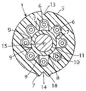
Fig. 1 illustrates eight tight buffered optical fibers 6 of the type described
hereinbefore in eight slots 7 in the jacket 5 which open inwardly toward a
strength
member 8. Each of the tight buffered optical fibers 6 can have, for example, a
glass
core encircled by one or more refracting layers which, in turn, are encircled
by one or
more protective layers of a protective material, such as a polymeric material.
The
outer diameter of each fiber 6 can be on the order of about 0.6 mm to about
0.9 mm.
The wall of the jacket 5 extends radially from the strength member 8 to the
outer
surface of the jacket 5, and plastic material of the jacket 5 forms the walls
of each slot
7 and is disposed between the slots 7 and the outer surface of the jacket 5.
Portions
9 of the jacket 5 engage the strength member 8 and connect the jacket 5 to the
strength member 8. The portions 9 are at circumferentially opposite sides of
each of
the slots 7.
In a preferred embodiment of the cable of the invention, there are no more
than
twelve slots 7 and at least two slots 7, and each slot 7 has one tight
buffered optical
fiber 6 therein.
The cross-sectional dimension of each slot 7 is selected in relation to the
cross-
sectional dimension of the optical fiber so that the fiber 6 can move
longitudinally with
respect to the jacket 5. For example, the slots 7 can have a width w (see Fig.
2) of the
order of 1.2 mm when the outer diameter of the optical fiber is on the order
of about
0.6 mm to about 0.9 mm. The depth of each slot 7, that is, the distance from
the outer
surface of the strength member 8 to the outermost arcuate portion of the slot
7, should
also be greater than the diameter of the optical fibers and can also be on the
order of
1.2 mm.
To prevent the outer layer of tight buffered optical fibers 6 from "sticking"
to the
jacket 5, several expedients are available. The slots 7 can contain a water
blocking
material, such as a water swellable powder 12 (see Fig. 6) or a thixotropic
jelly known
9
CA 02587364 2007-05-10
WO 2006/055538 PCT/US2005/041300
in the art. The fiber 6 can be coated with a release agent of the type
described in U.S.
Patent No. 6,137,936. The plastics used for the jacket 5 and the outer layer
of the
fibers 6 can be selected from plastics which do not stick to each other. If
the fibers 6
are received in the slots 7 while the plastic of the jacket 5 is still hot,
sticking of the
fibers 6 to the jacket 5 can be prevented or reduced by using a plastic for
the outer
layer of the fibers 6 which has a higher melting temperature than the melting
temperature of the plastic of the jacket 5.
As mentioned hereinbefore, an FTTH cable does not need a large number of
optical fibers, and it is desirable to use tight buffered optical fibers 6 so
that when a
fiber is pulled out of the cable or exposed, the fiber can be handled without
protection
and exposed optical fiber does not need protection, such as a sleeve. However,
if
desired, each of the slots 7 can have more than one optical fiber therein, and
if
desired, the slots 7 can have optical fibers therein which are not tight
buffered if the
advantages of tight buffered optical fibers are not needed.
To permit ease of mid-span access to the optical fibers, preferably, the slots
7
follow paths in the jacket 5 which are of alternating lay or S-Z lay as
described and
illustrated in said Patent No. 5,390,273 for the buffer tubes 4-9 and as
illustrated in
Fig. 5.
The strength member 8 illustrated in Fig. 1 comprises a core 10 and an
encircling layer 11 of plastic, the latter being sometimes called an "up
jacket" and
included, when necessary, to provide the desired spacing between the slots 7
when
the core 10 need not have the diameter required for such spacing. The core 10
is
formed by a material of high tensile strength, e.g. a steel wire or rod or
epoxy
impregnated glass or aramid fibers. Thus, the core 10 provides the required
resistance to tensile forces, e.g. up to 600 pounds, encountered during
handling,
installation and suspension of the cable. Preferably, the core 10 is also able
to
withstand and resist compression and tension forces caused by temperature
changes
from -50 C to 85 C. The temperature coefficient of expansion and contraction
of the
core 10 is less than such coefficient of the jacket 5 so as to reduce
longitudinal
expansion and contraction of the jacket 5 connected to the strength member 8
by the
portions 9.
Fig. I illustrates the cable I with a core 10 with an up jacket layer 11 of
plastic.
In Figs. 2-4, the strength member is a bare core 10a of glass fibers which can
be
impregnated with an epoxy resin as is known in the art. Such a core I Oa has
high
CA 02587364 2007-05-10
WO 2006/055538 PCT/US2005/041300
tensile strength and a low coefficient of expansion and contraction and is
resistant to
contraction forces.
To avoid damage to the optical fibers 6, the material encircling the optical
fibers
6, the jacket 5 in the cable of the invention, should have sufficient
connection to the
strength member 8 to prevent longitudinal and circumferential movement of such
material (the jacket 5) with respect to forces applied to the cable by reason
of handling
of the cable, temperature changes and suspension of the cable. The major
forces
normally are the pulling forces during installation of a cable which cause
shear
stresses at the interface of the portions 9 and the strength member 8 or I Oa.
Such
shear stresses will vary depending on the diameters of the cable components
and on
the installation methods and tools used. For example, if the optical fiber
cable 3
illustrated in Figure 3 has an outside diameter of 8.1 mm and a strength
member with
an outside diameter of 3.5 mm is to withstand a maximum pulling load of about
300
pounds when the cable is pulled with conventional cable grip having a length
of 225
mm, the maximum shear stress at the interfaces is calculated to be
approximately
0.97 N/mm2. Thus, the adhesion between the portions 9 and the strength member
8
or I Oa for such a cable must provide a resistance to movement of the portions
9
relative to the strength member 8 or 10a which is greater than 0.97 N/mm2.
However,
such resistance must be less than the yield or rupture strength of the
material of the
jacket 5, i.e. should not exceed 90% of such strength and preferably, should
not
exceed 80% of such strength.
However, it is also desirable that it be simple and easy to expose individual
fibers for access thereto intermediate the cable ends for connection of a
fiber or fiber
to optical equipment. Also, if the cable is to be terminated at an end, it is
desirable to
be able to expose all the optical fibers at the end in a simple and easy
manner.
Accordingly, there are the conflicting requirements of a strong connection
between the
jacket 5 for preventing relative longitudinal movement between the jacket 5
and the
strength member 8 and of a manually separable connection between the jacket 5
and
the strength member 8.
In the preferred embodiments of the cables of the invention, the materials of
the
jacket 5 and of the strength member 8 preferably are sized, treated and/or
selected so
that there is a connection between the portions 9 and the strength member 8
which,
by adhesion and/or friction therebetween, prevents longitudinal movement
between
the jacket 5 and the strength member 8 or 10a when the pulling force on the
cable is
11
CA 02587364 2007-05-10
WO 2006/055538 PCT/US2005/041300
up to 300 pounds but, nevertheless, permits separation of the jacket 5 from
the
strength member 8 with manual forces of not more than 100 pounds applied
radially
away from the strength member 8 or 1 Oa after the jacket 5 has been
longitudinally cut
along diametrically opposite lines. Preferably, the manual force required to
pull the
jacket 5 away from the strength member 8 or 1Oa is not more than about 20
pounds
and does not exceed 75 pounds.
For example, if the strength member is made of metal or glass fibers and is
bare, i.e. is a core I Oa without an encircling layer, and the jacket 5 is
made of plastic,
the material of the jacket 5 and circumferential length of the portions 9 at
the surface
of the strength member can be selected so that the desired resistance to
longitudinal
movement between the jacket 5 and the strength member 8 can be obtained by
adhesion and/or the coefficient of friction between the jacket 5 material and
the
strength member material. The material of the jacket 5 can be, for example,
polyvinylchloride or polyethylene. However, the jacket portions can be readily
separated from the strength member by manual forces applied to the jacket
radially of
the cable axis.
As further examples, if the strength member 8 has an up-jacket 11 of plastic,
the desired resistance to such longitudinal movement and ease of separation of
the
jacket 5 from the strength member 8 can be obtained by making the jacket 5 of
a
plastic which does not bond, or only weakly bonds, to the plastic of the up
jacket, or
by coating the outer surface of the up-jacket 11, or the inner surfaces of the
portions
9, with a release agent known in the art. The preferred release agent is the
Miller
Stephenson MS-143 DF, the release agent described in U.S. Patent No.
6,137,936.
Plastics which do not bond, or which only weakly bond, include those which are
immiscible and those which have different melt temperatures. Polar and non-
polar
plastics are immiscible and, for example, the up-jacket 11 can be formed from
a polar
plastic and the jacket 5 can be formed from a non-polar plastic or vice versa.
Combinations of such plastics which weakly adhere are polyvinylchloride (PVC)
and
polyethylene (PE), polypropylene (PP) and PVC, PP and polybutylene (PBT), PP
and
polyethylene terephthalate (PET), PE and PET and PE and PBT. If plastics with
different melt temperatures are used, the plastic with the higher melt
temperature
would be used for the up jacket 11 and the plastic for the jacket 5 would have
a lower
melt temperature so that when it is applied it would not cause melting of the
up jacket
material and significant mixing of the two plastics. Thus, for example, PBT
could be
12
CA 02587364 2007-05-10
WO 2006/055538 PCT/US2005/041300
used for the up-jacket 11 and PE or PP for the jacket 5 or PBT or PET as the
up-
jacket 11 and PVC as the jacket 5.
Alternatively, if the strength member 8 has an up jacket 11 of plastic
material
which is the same as the plastic material of the jacket 5, as shown in Figs. 9
and 10,
the up-jacket 11 and jacket 5 can be co-extruded so that the portions 9 are
integral
with the up jacket 11. However, in such an embodiment, the circumferential
lengths of
the portions 9, at the up jacket portion 11, should be selected so that the
required
resistance to longitudinal movement of the jacket portion 5 relative to the up
jacket
portion 11 and the ease of separation of the jacket portion 5 from the up-
jacket portion
11 by radially applied forces set forth hereinbefore are met. Thus, manual
forces of
not more than 100 pounds, and preferably, not more than 20 pounds, applied
radially
of the strength member 8, will cause the portions 9 to rupture at the up-
jacket portion
11 and will cause the jacket portion 5 to separate from the strength member 8.
On the
other hand, the circumferential length of portions 9 should also be selected
so that
when the pulling force on the cable is up to 300 pounds, the portions 9 will
not
separate from the up-jacket portion 11. It has been found that such results
can be
obtained because the force required to rupture the portions 9, when the force
is
applied to the portions 9 in the direction parallel to the axis of the
strength member 8,
is significantly greater than the force required to rupture the portions 9
when the force
is applied to the portions 9 radially of the axis of the strength member 8.
The
circumferential lengths of the portions 9 where they meet the up-jacket potion
11
depend upon the plastic material used and the tensile force required to
rupture such
material. For example, if the jacket 5 and the up jacket 11 are both made of
polyethylene, the circumferential lengths of the portions 9 at the up-jacket
portion 11
can be from about 0.1 mm to about 0.5 mm.
It is not necessary that the jacket portion 5 rupture at the portions 9 at the
up-
jacket portion 11. The portions 9 in Fig. 9, being of the smallest
circumferential length,
form a line of weakening, but if desired, the line of weakening can be
radially outward
of the up jacket portion 11 and circumferentially adjacent the slot on duct 7
as
illustrated in Fig. 10. Thus, the portions 9 can have a circumferential length
such that
they will not rupture with a force sufficient to rupture the jacket portion 5
at the lines of
weakening 24 and 25 which are spaced radially outwardly from the portions 9
and
which provide therebetween jacket material of a circumferential length less
than the
circumferential length of the portions 9. Although two opposed lines of
weakening 24
13
CA 02587364 2007-05-10
WO 2006/055538 PCT/US2005/041300
and 25 are shown, it will be apparent that a single line of weakening 24 or 25
can be
used.
For the purpose of obtaining access to the optical fibers 6, it is important
to be
able to determine the circumferential positions of the slots 7, and hence, the
locations
of the fibers 6, from externally of the various embodiments of the cables of
the
invention, especially when, as in the cables of the invention, the slots 7
have an
alternating hand or S-Z lay. When mid-span access is desired, it is desirable
to be
able to expose one, or less than all, optical fiber without exposing other
optical fibers.
For this reason, the cables of the invention preferably have one or more
visible
indicium at the outer surface of the jacket 5.
For example, the outer surface of the jacket 5 can have visible markings
thereon or stripes of plastic different in color from the plastic of the
remainder of the
jacket 5. Thus, there can be a plurality of longitudinal markings or stripes
which
overlie and follow the positions of the underlying slots 7. Preferably, the
indicia are
physical modifications of the jacket 5, not only to identify the positions of
the slots 7,
but also to provide guides for tools for cutting the jacket 5. Preferably,
also, the indicia
provide diametrically opposite lines of weakening in the jacket 5 for
providing
exposure of all the optical fibers 6 at a cable end as described hereinafter.
In the preferred embodiments of the cable 3 of the invention, the jacket 5 has
two diametrically opposite, longitudinal, V-shaped grooves 13 and 14 which
extend
inwardly from the outer surface of the jacket 5 and which throughout their
lengths
radially overlie, a pair of diametrically opposite slots 7 and hence, the
optical fibers
therein. Preferably, the bottom of each groove 13 and 14, i.e. the portion of
the
groove which is nearest the axis 15 of the cables, lies on a line which
extends radially
from the axis 15 and intersects the cores of the optical fibers 6 in the slots
7 adjacent
to the grooves 13 and 14.
Although a greater number of similarly disposed grooves 13 and 14 could be
used, e.g. a groove adjacent each slot 7, two grooves 13 and 14 are normally
sufficient. If it is desired to distinguish one of the grooves from the other
of the
grooves, the groove 14 can be visibly distinguished by one or more ridges or
ribs 17
and 18 extending alongside the groove 14 and extending outwardly from the
jacket 5.
Alternatively, or in addition, the grooves 13 and 14 can have different cross-
sectional
shapes, e.g. one can be V-shaped as shown and the other can be arcuate.
14
CA 02587364 2007-05-10
WO 2006/055538 PCT/US2005/041300
In all the embodiments of the cable of the invention, water or moisture
blocking
material can be used in, or adjacent, the slots 7 for protecting the optical
fibers 6 with
respect to water and moisture. Such water blocking material is well known in
the art
and includes water absorbing or water swellable powders, tapes and yarns,
thixotropic
gels and petroleum greases.
Fig. 6 is a fragmentary, cross-sectional view of a cable 2a which is similar
to
the cable 2, but which has water blocking materials therein. The core 10a in
Fig. 6
can be the same as the core 10a in Fig. 2 or can be twisted glass fibers or
steel wires.
In Fig. 6, the core 10a is encircled by a plastic layer 11 which is encircled
by a
layer 19 of a known type of water swellable tape. In addition to or in place
of, the tape
layer 19, the slots 7 can contain a water blocking powder 12 of a known type,
such
powder 12 serving the dual function of providing moisture protection for the
optical
fibers 6 and of preventing sticking of the optical fibers 6 to the jacket 5.
Fig. 7 is a greatly enlarged, fragmentary, cross-sectional view of a slot 7
with a
tight buffered optical fiber 6 and water blocking yarns 20 therein. The yarns
20 are of
a known type which absorb moisture, and the yarns 20 can be either loosely
received
in the slot 7 or helically wrapped around the optical fiber 6.
The tight buffered optical fiber 6 comprises a core 21 of glass, e.g. silica
glass,
doped or undoped, a layer or layers 22 which are normally applied by the
manufacturer of the optical fiber and a buffering layer 23 of relatively soft
plastic. The
layer or layers 22 comprises a cladding layer of glass having an index of
refraction
lower than the index of refraction of the core 21.
The buffering layer 23 can include one or more layers of extruded plastic such
as polyethylene, polypropylene, polyvinylchloride, nylon, ethylenevinylacetate
or
polyurethane.
As previously indicated, the location of an optical fiber 6 along the axial
length
of the cable is indicated by the grooves 13 and 14. While a greater number of
grooves, one for each slot 7, can be used, it can be sufficient to use only
two grooves
13 and 14 even though the number of slots 7 is greater than two because each
of the
slots 7 has a predetermined physical position in relation to the grooves. For
example,
two of the slots 7 underlie the grooves 13 and 14, and the remaining' slots 7
are
circumferentially spaced from the grooves 13 and 14 by known amounts.
Accordingly,
an optical fiber 6 can be readily accessed intermediate the ends of a cable by
cutting
CA 02587364 2007-05-10
WO 2006/055538 PCT/US2005/041300
the jacket 5 axially along a line overlying the fiber 6 and radially from the
outer surface
of the jacket 5 to the slot 7 containing the fiber 6 to be accessed.
However, when a cable is to be terminated, e.g. at a terminal or rack, it is
desirable to have easy and rapid access to the end portions of all the fibers
6 in the
cable. Thus, as shown in Fig. 8, the jacket 5 can be axially cut along both
grooves 13
and 14 and radially inwardly to the underlying slots 7, and thereafter, since
the bond of
the portions 9 to the strength member core 10a is manually frangible at the
core 10a,
the portions of the jacket 5 at opposite sides of the grooves 13 and 14 can be
manually and readily pulled apart to expose the end portions of all the
optical fibers 6
in the cable 3. In other words, with only two axial and radial cuts in the
jacket 5, the
end portions of all the optical fibers 6 in the cable can be exposed.
The structure of the cable of the invention permits a manufacturing process
which is simpler than the process needed for manufacturing the stranded loose
tube
cable and the slotted core cable. In the process for manufacturing the cable
of the
invention, the jacket and the fibers are simultaneously applied to the
strength member,
and in the case of S-Z stranding of the fibers around the strength member,
reversal of
the fiber pay-off reels is not required and the fibers are precisely aligned
with the slots
or ducts. When the jacket bears indicia of the location of the slots or ducts,
the indicia
can be applied at the same time as the jacket is applied and the slots or
ducts are
formed, and the indicia will precisely follow the positions of the slots or
ducts. The
separate steps of manufacturing a slotted core before the fibers are inserted
in the
slots of a slotted core or manufacturing buffer tubes with fibers therein
before the
jacket is applied are eliminated.
Although additional steps can be used when it is convenient for a specific
cable
design or process, an advantage of the process for the manufacture of the
cable of
the invention is that the process can comprise only the following steps:
(1) Manufacture of a central strength member preferably with a plastic up-
jacket but, alternatively, without such up-jacket; and
(2) Feeding the strength member and optical fibers through a die, which can
be rotatable for S-Z stranding, which simultaneously extrudes the jacket
material over
the strength member, forms the slots or ducts and inserts the fibers in the
slots or
ducts. If the strength member is without an up jacket, the strength member can
have
an up-jacket extruded thereover before or during the extrusion of the jacket
material.
16
CA 02587364 2007-05-10
WO 2006/055538 PCT/US2005/041300
The die can also apply the identifying stripes to, or form the identifying
grooves
in, the jacket.
Although preferred embodiments of the present invention have been described
and illustrated, it will be apparent to those skilled in the art that various
modifications
may be made without departing from the principles of the invention.
17