Note: Descriptions are shown in the official language in which they were submitted.
CA 02587966 2007-05-16
WO 2006/104522 PCT/US2005/042375
DUAL ELECTROLYTE MEMBRANELESS MICROCHANNEL FUEL CELLS
CROSS-REFERENCE TO RELATED APPLICATIONS
[0001] This application is a continuation-in-part application of U.S. patent
application Serial No. 11/150,622 filed
on June 10, 2005, which claims the benefit of priority to U.S. provisional
patent application Serial No. 60/579,075
filed on June 10, 2004, and to U.S. provisional patent application Serial No.
60/629,440 filed on November 19,
2004, which are each incorporated herein by reference in their entirety.
STATEMENT REGARDING FEDERALLY FUNDED RESEARCH OR DEVELOPMENT
[0002] The invention described herein was made in the performance of work
under Army Research Office contract
DAAD 19-03-C-0100, under NSF contract ACT-0346377, and under NSF Grant ECS-
0335765, and is subject to the
provisions of Public Law 96-517 (35 U.S.C. 202) in which the Contractor has
elected to retain title.
FIELD OF THE INVENTION
[0003] The invention relates to microfluidic flow cells in general, and more
particularly, to electrolyte mixtures
that may containi separate alkaline and acidic solutions having fuels and
oxidants dissolved therein. These
electrolyte mixtures can be incorporated into different types of microfluidic
flow cells including those wliich create
a diffusive boundary layer or "virtual interface" between a plurality of
laminar flows.
BACKGROUND OF THE INVENTION
[0004] Recently, there has been much emphasis on the development of novel fuel
cell technologies as portable
high energy density power sources for consumer electronics, military
applications, medical diagnostic equipment,
and mobile communication. These systems must be lightweight, energy efficient,
and able to operate for long
periods of time without refueling. This interest in miniaturization of power
sources has been expanded to
microsystems for powering MEMs and related devices, such as "lab-on-a-chip"
systems and micro-pumping
assemblies. Merging the development of fuel cells with microtechnology lias
led to the study of micro-fuel cells and
their application to micro-devices, as well as to a myriad of portable
systems.
[0005] Additionally, the Department of Defense (DOD) has frequently expressed
a need for high-energy,
lightweight power sources for the soldier. The power needs of the individual
warrior is the main driver behind the
DOD search for power sources that are lighter, can deliver more power, have
longer running times and have fewer
overall logistic problems. Today's soldier is burdened with 16 different
batteries weighing 2.5 pounds. With the
new Army vision of the Land Warrior, version 1, the total number of batteries
should be reduced to 4 and the weight
should be reduced to 2.0 pounds. In the future, an Army soldier is expected to
have >1 KW of power on a 72-hour
mission carrying even less weight. Such goals can only be met by a combination
of rechargeable batteries and fuel
cells that can be preferably reduced in size and weight or miniaturized.
[0006] Micro-fuel cells, which are similar to conventional low temperature
fuel cells, rely on a polymer electrolyte
membrane (PEM), a part of the membrane electrode assembly. The PEM serves as
an ionic conductor for generated
protons, and also acts as a physical barrier for separating an oxidizer and a
fuel within the cell. Either or a variety of
simple organic fuels, such as methanol or ethanol, can be used as a fuel. The
oxidizer is typically oxygen from air.
[0007] One of the most challenging aspects of the miniaturization of fuel
cells is attributed to the reliance on the
PEM component, which itself suffers from numerous problems including: drying
out of the membrane (especially at
CA 02587966 2007-05-16
WO 2006/104522 PCT/US2005/042375
high operating temperatures), fuel crossover into the oxidizer, in addition to
the high expense typically associated
with membrane development. All of these problems are fiuther compounded by the
need to decrease the thickness
(further increasing the complication of the network structure) of the PEM when
designing a micro-fuel cell.
Incorporation of a PEM has been achieved however in a number of micro-fuel
cells studied to date. A number of
these are biofuel cells, for example. Recently, there have also been a number
of biofuel cells that employ enzymes
as catalysts at both the anode and cathode surfaces in order to achieve some
degree of selectivity to the fuel/oxidizer
thus decreasing the problem of fuel crossover and eliminating the need for a
PEM. While these enzymatic redox
systems can provide the desired selectivity, they typically generate very low
power and suffer from all of the
problems attendant to the use of enzymes, with long-term stability being
especially problematic. The PEM also
takes up much of the space in the non-enzymatic micro-fuel cells being
developed, thus limiting the size of the final
device. Despite significant advances in PEM fuel cells that have been achieved
in the last decade, there are still a
number of unresolved issues that have limited their use. The PEM remains a
relatively expensive and often
unreliable component of PEM fuel cells. Thus, one of the more serious
complicating factors (among numerous
others) in the miniaturization of fuel cells has been the instability of the
PEM and the membrane electrode assembly
under operating conditions.
[0008] Many advantages are therefore provided in fuel cells that can designed
without a PEM coniponent. The
dimensions of the fuel cell could be reduced, for example, and the time and
effort required for fabrication and
system integration could also be reduced. Moreover, particularly for niicro-
fuel cell designs, eliminating the use of
PEMs could significantly reduce the overall cost of such devices and also
remove other particular ensuing problems
such as the need for enzymatic selectivity in biofuel cells.
[0009] An alternative to PEM fuel cells are "membraneless" fuel cells that
were designed to operate without a
PEM. Some of these devices involve the laminar flow of fuel and oxidant
streams within micro-fuel cell structures.
It has been farther demonstrated that laminar flow can be used to create a
micro-fuel cell with a diffusive interface
serving as or in lieu of the inembrane, thus eliminating the need for a PEM.
For example, one design is based on a
Y-shaped microchannel injected with two fuels flowing in a relatively side-by-
side configurationi. (Choban, E. R.;
Markoski, L. J.; Wieckowski, A.; Kenis, P. J. A., J. Power Soui-ces 2004, 128,
54-60). Due to the approach used,
the only way to increase the interface area would be to increase channel depth
(which may be difficult or costly to
achieve using certain manufacturing techniques such as photolithography, which
also has difficulty producing large
vertical walls) and/or to increase channel length (the maximum useful length
may be limited however by the
dynamics of parallel and laminar flow). Either attempt to increase the
interface area would present other
considerations and additional problems that would need to be addressed.
[0010] Other examples of a membraneless fuel cells are disclosed in U.S.
Patent No. 6,713,206, issued on
March 30, 2004 to Markoski et al. (hereinafter "Markoski I") and U.S. Patent
Publication No. 20040072047,
published April 15, 2004 also to Markoski et al. (hereinafter "Markoski II"),
which are incorporated by reference
herein in their entirety. Each disclose the use of laminar flow induced
dynamic conducting interfaces for use in
microfluidic electrochemical cells generally, including batteries, fuel cells,
and photoelectric cells. Based on the
examples and geometry described in Markoski I (see Fig. 7), a laminar flow
regime appears to have been set-up over
an area of some centimeters in length by a depth of the thickness of a glass
cover slip, which thickness dimension is
not reported. Sources of supply for glass cover slips having thicknesses in
the range of about 0.1 nun to 0.4 mm are
readily located on the Internet. Even assuming a thickness of 0.4 mm, the
laminar flow interface that is described in
Markoski I in the examples provided would be no larger than 0.4mm high. As a
result, the interface area between
the two fluids per millimeter of channel length as they flow in contact
through the laminar flow channel can be
2
CA 02587966 2007-05-16
WO 2006/104522 PCT/US2005/042375
calculated for this device using dimensions given in Markoski I as 0.4 mm2
(0.4 nun depth x 1 mm length) per
millimeter of channel length. The interface area per unit volume can also be
calculated. Assuming the channel
width is at least 11 nnn (the bottom of the channel has two electrode strips
side-by-side with a 5 mm gap between
them, and the width of the two electrodes is described as 3 mm each), there is
4.4 mm3 of fluid (0.4 depth nun x
11 mm width x 1 mm length) per millimeter of channel length. Therefore, the
interface area per unit volume for the
device described in Markoski I is 0.091 mmZ (0.4 mm2 area / 4.4 mm3 volume)
per cubic millimeter of fluid.
Meanwhile, the device shown in Markoski II is described as having a 1 mm by 1
mm channel (Fig. 13). The
interface area in this device per millimeter of chaimel length is therefore 1
mmZ and the interface area per cubic
millimeter of fluid volume is 1 mm2 [i.e., lmm Z area / 1 mm 3 volume] (volume
= 1 mm width x 1 mm length x
1 mm depth). Since the amount of a substance that can be caused to react is
proportional to the area, of the interface
between the two laminar flows, one problem that needs to be solved is how to
arrange for larger areas of the
interface between such laminar flows and also to increase the interface area
without also increasing the volume of
fluid.
[0011] Membraneless micro-fuel cell studies in the past typically focused on
several common fuel sources. For
example, formic acid fuel cell systems, or those relying on vanadium redox
chemistry, are well known. But the
power densities reported for formic acid systems, as well as the power
generation from any single micro-fuel cell
device, is often lower than that required for many useful applications in
which micro-fuel cells would be of great
value, such as cell phones and other small portable devices. Another fuel that
has been studied extensively is pure
hydrogen. Because it can be oxidized at very low overpotentials on platinum
catalyst surfaces, this fuel can readily
be employed as a model system to explore other aspects of membraneless micro-
fuel cells, such as geometry and
flow rate. Likewise, hydrogen has a much higher energy conversion efficiency
than most other fuels, thus
increasing the power generation from the micro-fuel cell device.
[0012] In particular, studies have been performed with devices employing
hydrogen/oxygen (H2/02) fuel cell
systems. These and other fuel cell systems such as those described in Markoski
I relied upon single or common
electrolyte (acid or alkaline) system. These systems provide modest power
levels but are attractive because they
generate only H20 as a by-product of the fuel cell reaction. Neverflieless it
has been observed that the resulting
thermodynamic potentials from these single electrolyte systems remain
relatively modest.
[0013] There is a need for flow cell structures and fuel cells capable of
generating higher potentials so they can be
more suitable for widespread use in everyday applications.
SUMMARY OF THE INVENTION
[0014] Various aspects of the invention described herein relate to improved
flow cell structures and their methods
of use and manufacture. In particular, these methods and apparatus can be
adapted to provide planar microfluidic
membraneless fuel cells. Various aspects of the invention described herein
provide membraneless fuel cells
utilizing multiple electrolytes containing a variety of fuel/oxidant mixtures
in an acid/base environment. It shall be
understood that alternate embodiments of the invention herein relating to each
aspect of the invention may be
applied separately or together in combination with other aspects of the
invention.
[0015] One aspect of the invention described herein relates to a planar
membraneless microchannel structure. In
one embodiment, the structure is useful in constructing a planar membraneless
microchannel fuel cell (PM2FC) and
for generating electrical power by consuming fuel components (e.g., a
substance capable of being oxidized and a
substance capable of being an oxidizer) within the structure so that the fuel
components are reacted and electrical
power is produced that can be extracted from terminals of the fuel cell
embodying the planar membraneless
3
CA 02587966 2007-05-16
WO 2006/104522 PCT/US2005/042375
microchannel structure. However, the features of the planar membraneless
microchannel structure described
hereinbelow are also useful in other applications. Examples of other
applications include certain kinds of diffusion
controlled chemical reactions and applications of those reactions, such as in
diagnostic tests; and controlled
processing of materials, based on controlled fluid dynamics.
[0016] The planar membraneless microfluidic fuel cell designs provided herein
have several advantages over
previous designs. In particular, the fuel designs herein take advantage of the
laminar flow conditions that exist
between two large parallel plates with a microscopic separation between them.
As described hereinbelow in greater
detail (see FIG. 1), a preferable embodiment of the present invention uses a
structure referred to as a "flow control
structure," and is designed to establish a condition of laminar flow of two
solution streams flowing on either side of
the flow control structure prior to the two streams coming into contact. The
flow control structure may also be
referred to as a "tapered cantilever" (see U.S. provisional patent application
Serial No 60/579,075, which is
incorporate by reference herein). In some preferable embodiments, the
cantilever includes a taper at its thin edge
that is tapered down to as thin a structure as can be obtained by a chemical
etching process, such as a few atomic
diameters or virtually zero thickness, but just thick enough to maintain
structural integrity. In other alternate
embodiments, the taper at its thin edge is as thick as 50 microns. In some
embodiments, the flow control structure is
tapered on only one side, or is tapered on both sides. In some embodiments, in
which tapers are present on both
sides, it is contemplated that the taper angles may or may not be equal or
symmetric when measured with respect to
a boundary layer between the two fluids. In some embodiments, there is no
taper on the flow control structure. The
advantages that accrue when adopting the planar microfluidic configuration
over other (e.g. microchannel)
configurations include:
= deposition of electrode materials becomes a manageable process based on
sputtering and/or evaporation
techniques,
= the large solution/electrode interfacial area available in this design can
lead to higher power devices,
= the stacking of devices can lead to potentially high power systems taking up
small volumes, and
= most processing and manufacturing routines are industrially-scalable and in
the future could be carried out
using polymer substrates.
[0017] In one aspect, the invention relates to a flow cell structure useful
for providing laminar flow regimes in a
plurality of fluids flowing in mutual contact in a laminar flow channel. The
flow cell structure comprises a laminar
flow chaimel defined within a flow cell structure; at least two entrance
apertures defined witliin the flow cell
structure, a first entrance aperture configured to admit a first fluid flow
into the laminar flow channel and a second
entrance aperture configured to admit a second fluid flow into the laminar
flow channel, the first entrance aperture
and the second entrance aperture configured to provide respective entry of the
first fluid flow and the second fluid
flow from the same side of the laminar flow channel; a flow control structure
situated adjacent the at least two
entrance apertures for admitting the fluid flows into the laminar flow
channel, the flow control structure configured
to cause each of the fluid flows to flow in a laminar flow regime within the
laminar flow channel; and at least one
exit aperture defined within the fuel cell structure for permitting the fluids
to exit the laminar flow channel; wherein
the flow cell structure is configured to provide laminar flow regimes in two
fluids flowing in mutual contact in the
laminar flow channel. In one embodiment, the first entrance aperture and the
second entrance aperture configured to
provide respective entry of the first fluid flow and the second fluid flow
from the same side of the laminar flow
channel. In one embodiment, the flow control structure has at a downstream
terminal edge thereof a thickness of not
more than 50 microns. In one embodiment, the laminar flow channel is
rectangular in cross-section.
4
CA 02587966 2007-05-16
WO 2006/104522 PCT/US2005/042375
[0018] In one embodiment, the width of the first entrance aperture and the
width of the second entrance aperture
are equal. In one embodiment, the width of the first entrance aperture and the
width of the second entrance aperture
are equal, and are also equal to the width of the laminar flow channel
immediately after the entrance apertures. In
one embodiment, the width of the first entrance aperture and the width of the
second entrance aperture are equal,
and are also equal to the width of the entire laminar flow channel.
[0019] In one embodiment, there are a first and second diffuser/condenser
structures, each transferring a first and
second fluid entering through a first and second inlet from a first and second
inlet end to a first and second entrance
aperture into the laminar flow channel at a first and second outlet end. Each
of said diffuser/condenser structures
mechanically diffuses or condenses the width of its respective fluid from the
width of its respective fluid at its
respective inlet end to the width of its respective entrance aperture at its
outlet end. In one embodiment, the width
of the two diffuser/condenser structures at their inlet ends can be different
from each other and have any width, but
at their outlet ends at their respective entrance apertures, the width of the
two diffuser/condenser structures is the
same, and is optionally and preferentially equal to the width of the beginning
of the laminar flow channel. In one
embodiment, the widths of the diffuser/condenser structures at the entrance
aperture, of the entrance aperture and of
the laminar flow chamiel at the entrance aperture are equal. In one
embodiment, the side walls of the first
diffuser/condenser structures at its outlet end are aligned with the side
walls of the second diffuser/condenser
structure at its outlet end. In one embodiment, the side walls of the
diffuser/condenser structures at their respective
outlet ends are aligned with each other and with the side walls of the laminar
flow channel at the entrance apertures.
[0020] In one embodiment, the width of the diffuser/condenser structures at
their outlet ends is at least three times
its depth (i.e., at the entrance apertures - the entrance aperture is at the
end of the diffuser/condenser structure and
beginning of the laminar flow channel, it is the plane of connection between
the two). In one embodiment, the
width of the diffuser/condenser structures at the entrance apertures is at
least five times its depth. In one
embodiment, the width of the diffuser/condenser structures at the entrance
apertures is at least ten times its depth.
[0021] In one embodiment, the widths of the diffuser/condenser structures at
their outlet ends, the entrance
aperture, and the laminar flow channel at the entrance aperture are equal, and
the width of the diffuser/condenser
structures at the entrance apertures is at least three times its depth. In one
embodiment, the widths of the
diffuser/condenser structures at their outlet ends, the entrance aperture, and
the laminar flow channel at the entrance
aperture are equal, and the width of the diffuser/condenser, structures at the
entrance apertures is at least five times
its depth. In one embodiment, the widths of the diffuser/condenser structures
at their outlet ends, the entrance
aperture, and the laminar flow channel at the entrance aperture are equal, and
the width of the diffuser/condenser
structures at the entrance apertures is at least ten times its depth.
[0022] In one embodiment, the width of the diffuser/condenser structures at
their outlet ends is at least three times
its depth, and the side walls of the diffuser/condenser structures at their
respective outlet ends are aligned with each
other and with the side walls of the laminar flow channel at the entrance
apertures. In one embodiment, the width of
the diffuser/condenser structures at the entrance apertures is at least five
times its depth, and the side walls of the
diffuser/condenser structures at their respective outlet ends are aligned with
each other and with the side walls of the
laminar flow channel at the entrance apertures. In one embodiment, the width
of the diffuser/condenser structures at
the entrance apertures is at least ten times its depth, and the side walls of
the diffuser/condenser structures at their
respective outlet ends are aligned with each other and with the side walls of
the laminar flow channel at the entrance
apertures.
[0023] In one embodiment, the side walls of the diffuser/condenser structures
are aligned with each other and with
the side walls of the laminar flow channel.
CA 02587966 2007-05-16
WO 2006/104522 PCT/US2005/042375
[0024] In one embodiment, the diffuser/condenser structures are parallel to
each other and also to the laminar flow
channel. In one embodiment, the diffuser/condenser structures near their
outlet ends are parallel to each other. In
one embodiment, the diffuser/condenser structures near their outlet ends are
parallel to each other and also to the
laminar flow channel near the entrance apertures.
[0025] In one embodiment, the widths of the first entrance aperture and the
width of the second entrance aperture
are at least three times the depth of the respective entrance aperture, and
the entrance apertures are configured such
that a first fluid flowing through the first entrance aperture into the
laminar flow channel and a second fluid flowing
through the second entrance aperture into the laminar flow channel come into
contact along the width dimension. In
one embodiment the width of each entrance aperture is at least five times the
depth, and the entrance apertures are
configured such that a first fluid flowing through the first entrance aperture
into the laminar flow channel and a
second fluid flowing through the second entrance aperture into the laminar
flow channel come into contact along the
width dimension. In one embodiment the width of each entrance aperture is at
least ten times the depth, and the
entrance apertures are configured such that a first fluid flowing through the
first entrance aperture into the laminar
flow channel and a second fluid flowing through the second entrance aperture
into the laminar flow channel come
into contact along the width dimension.
[0026] In one embodiment, the width of the terminal edge of the flow control
structure is the same as the width of
the entrance apertures and is at least three times the depth of the entrance
apertures. In another embodiment, the
width of the terminal edge of the flow control structure is the same as the
width of the entrance apertures and is at
least five times the depth of the entrance apertures. In yet another
embodiment, the width of the terminal edge of the
flow control structure is the same as the width of the entrance apertures and
is at least ten tiines the depth of the
entrance apertures. In another embodiment, the flow control structure is
situated such that its terminal edge has a
width that is at least three times the depths of the entrance apertures
adjacent to it. In another embodiment, the
width of the terminal edge is at least five times the depths of the entrance
apertures adjacent to it. In yet another
embodiment, the width of the terminal edge of the flow control structure is at
least ten times the depths of the
entrance apertures adjacent to it. In another embodiment, the flow control
device is situated such that its terminal
edge has a width that is at least three times the depths of at least one of
the entrance apertures adjacent to it. In
another embodiment, the width of the terminal edge is at least five times the
depth of at least one of the entrance
apertures adjacent to it. In yet another embodiment, the width of the terminal
edge of the flow control structure is at
least ten times the depth of at least one of the entrance apertures adjacent
to it.
[0027] In one embodiment, the first fluid flows from the first
diffuser/condenser structure through the first
entrance aperture into a first half flow cell of the laminar flow channel and
a second fluid flows from the second
diffuser/condenser structure through the second entrance aperture into a
second half flow cell of the laminar flow
channel. In one embodiment, cross-sectional dimensions of the first entrance
aperture are the same as the cross-
sectional dimensions of the first half flow cell and the cross-sectional
dimensions of the second entrance aperture are
the same as the cross-sectional dimensions of the second half flow cell. In
one embodiment, cross-sectional
dimensions of the first entrance aperture are the same as the cross-sectional
dimensions of the first half flow cell and
the cross-sectional dimensions of the second entrance aperture are the same as
the cross-sectional dimensions of the
second half flow cell, and the diffuser/condenser structures are parallel to
their respective half flow cells at least
inunediately prior to and after the entrance apertures.
[0028] In one embodiment there is a boundary structure between the two
diffuser/condenser structures. In one
embodiment, the cross-sectional dimensions of the first entrance aperture are
the same as the cross-sectional
dimensions of the first half flow cell and the cross-sectional dimensions of
the second entrance aperture are the same
6
CA 02587966 2007-05-16
WO 2006/104522 PCT/US2005/042375
as the cross-sectional dimensions of the second half flow cell, and the
boundary structure is tapered and brings the
diffuser/condenser structures into being parallel to their respective half
flow cells prior to the entrance apertures, and
brings the two diffuser/condenser structures closer and closer until the meet
when the boundary structure tapers to
notliing. In one embodiment, the boundary structure gradually diminishes in
thickness until it disappears at the
entrance apertures. In one embodiment, the boundary structure forms one wall
of each diffuser/condenser structure
and both walls formed by the boundary structure are parallel to the opposite
walls of the respective
diffuser/condenser structures of which they form a wall. In one embodiment,
the boundary structure forms one wall
of each diffuser/condenser structure and one of the walls formed by the
boundary structure is parallel to the opposite
wall of the diffuser/condenser structure of which it forms a wall.
[00291 One aspect of an invention described herein is directed to flow cell
structures containing multiple
alkaline/acidic electrolyte solutions. An embodiment provided in accordance
with this aspect of the invention may
be configured as a fuel cell comprising a membraneless microchannel structure
and the use therein of various fuel
and oxidant mixtures within different alkaline/acidic electrolyte solutions,
or more generally, different electrolyte
systems in the input streams. A wide variety of fuels may be selected herein
which are substances capable of being
oxidized, including hydrogen and formic acid, while a number of oxidants may
be similarly chosen which are
substances capable of being an oxidizer, including oxygen and hydrogen
peroxide. Fuel components can flow in
controlled streams to react witliin these flow cell structures, which can be
otherwise modified as general purpose
reactor cells. Electrical power can be therefore produced and extracted from
terminals of such fuel cell structures.
In addition to the flow and fuel cell structures herein that can facilitate
laminar flow of the multiple electrolyte
solutions, the apparatus and methods of use thereof may include fuel and
oxidant mixtures dissolved in different
electrolytes (e.g., a first electrolyte for the oxidizer, and a second
different electrolyte for the substance being
oxidized). The presence of two or more electrolyte fluids permits the
operation of the fuel cell under conditions in
which an overpotential (or potential difference resulting fiom the differences
in the electrolytes themselves) permits
the cell to operate with a higher (or a modified) potential relative to the
expected potential for systems incorporating
a fuel and oxidant dissolved in either an entirely alkaline electrolytes or an
entirely acidic electrolytes. Accordingly,
micro-fuel cells can be provided as described herein for many widespread
applications including portable electronics
and mobile telecommunication devices.
[00301 Another embodiment of the invention provides microfluidic fuel cell
apparatus, methods of operating the
apparatus, and exainples of fuel/oxidant electrochemical pairs or combinations
that generate electrical power in
membraneless fuel cell systems. Due to the absence of a PEM component in the
flow cell structures described
herein, additional embodiments of the invention can be more readily adapted to
provide miniaturized or micro-fuel
cells that operate singularly or in combination together as fuel cell stacks.
The advantage of the use of dual
electrolytes in membraneless fuel cells was demonstrated by comparison of
three exemplary H2/O2 systeins. A
single electrolyte H2/O2 system, using either acid or base, was employed and
its mass-transport controlled behavior
was observed. Open circuit potentials (OCPs) between 0.850 and 0.940 V were
obtained. These open circuit values
are comparable to those obtained in some of the most efficient conventional
(macro) fuel cells. Power generation of
650 W in acid electrolyte and 920 W in alkaline electrolyte could thus be
achieved. Meanwhile, in accordance
with a preferable embodiment of the invention, a dual electrolyte H2/02
membraneless fuel cell system is provided
that can generate OCPs greater than 1.4 V. This embodiment of the invention
utilized the negative oxidation
potential of HZ dissolved in an alkaline electrolyte, and the positive
reduction potential of 02 when dissolved in an
acidic solution. Significant power increases, compared to the acid and
alkaline electrolyte systems alone, were
obtained, with 1.5 mW generated from a single devi". The OCPs observed were
consistently more than 500 mV
7
CA 02587966 2007-05-16
WO 2006/104522 PCT/US2005/042375
greater than those typically observed in single electrolyte fuel cells. Flow
rate and charmel thickness were
determined to be factors in the power output of the devices, as well as the i-
V curve shape. The establishment of a
liquid junction potential was also determined and the magnitude of this
potential was estimated to be on the order of
50 mV. This value, in conjunction with the kinetic effects of the electrolyte
in which the H2 and 02 were dissolved,
was observed to significantly affect the OCPs of the dual electrolyte systems.
For example, in an alternate
embodiment of the invention in which the alkaline electrolyte stream flowed at
the anode and the acidic electrolyte
stream flowed at the cathode, it was observed that the resulting liquid
junction potential and slow kinetics were
deleterious to the OCP. In the reverse dual electrolyte system, however, the
liquid junction potential and optimized
kinetics contributed favorably to the system performance. The reverse dual
electrolyte system may be advantageous
nonetheless for some applications despite some of its observed limitations.
[0031] In a preferable embodiment of the invention, a planar microfluidic
membraneless fuel cell was constructed
and compared to single electrolyte H2/O2 systems under analogous conditions.
The selected fuel for this
embodiment was H2 dissolved in 0.1 M KOH (pH 13), and the oxidant was 02
dissolved in 0.1 M H2SO4 (pH 0.9).
The calculated thermodynamic potential for this system is 1.943 V (when 1 M H2
and 02 concentrations are
assumed). This value is well above the calculated thermodynamic maximum of
1.229 V for an acid, or alkaline,
single electrolyte H2/02 fnel cell. In other embodiments of the invention,
open circuit potentials in excess of 1.4 V
were achieved with the dual electrolyte systems provided herein. In general,
these systems provide a 500 mV
increase in the open circuit potentials that were observed for single
electrolyte 112/02 systems. The dual electrolyte
fuel cell system herein provide power generation of 0.6 mW/cm2 from a single
device, which is nearly 0.25 mW/cmZ
greater than the values obtained for comparable single electrolyte H2/02 fuel
cell systems. Microchannels of varying
dimensions can be also employed in fixrther embodiments of the invention to
analyze the differences between known
single systems in comparison to dual electrolyte 112/02 systems herein. It
should be noted that channel thickness
variation and the flow rates can be varied accordingly to provide desired
power generation.
[0032] The foregoing and other objects, aspects, features, and advantages of
the invention will become more
apparent from the following description and from the claims. Other goals and
advantages of the invention will be
fizrther appreciated and understood when considered in conjunction with the
following description and
accompanying drawings. While the following description may contain specific
details describing particular
embodiments of the invention, this should not be construed as limitations to
the scope of the invention but rather as
an exemplification of preferable embodiments. For each aspect of the
invention, many variations are possible as
suggested herein that are known to those of ordinary skill in the art. A
variety of changes and modifications can be
made within the scope of the invention without departing from the spirit
thereof.
BRIEF DESCRIPTION OF THE DRAWINGS
[0033] The objects and features of the invention can be better understood with
reference to the drawings described
below, and the claims. The drawings are not necessarily to scale, emphasis
instead generally being placed upon
illustrating the principles of the invention. In the drawings, like numerals
are used to indicate like parts throughout
the various views.
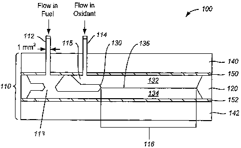
[0034] FIG. 1 is a drawing showing a schematic sectional side view of a planar
microfluidic membraneless micro-
fuel cell that may operate with single or dual electrolyte solutions according
to various principles of the invention.
[0035] FIG. 2 is a diagram depicting the process flow for fabricating silicon
microchannel flow cells from a silicon
single crystal wafer that is shown in side section, according to principles of
the invention.
8
CA 02587966 2007-05-16
WO 2006/104522 PCT/US2005/042375
[0036] FIG. 3 is a diagram that illustrates various embodiments of laminar
flow microchannels comprising flow
control structures, according to principles of the invention.
[0037] FIG. 4 is a diagram that shows a typical cyclic voltammogram of
polycrystalline Pt on a Kapton substrate,
according to principles of the invention.
[0038] FIG. 5 is a picture that shows a planar silicon microchannel into which
millimolar solutions of Fez+ and
BPS are being fed, according to principles of the invention.
[0039] FIG. 6 is a picture that shows an example of a silicon microchannel
flow cell configured as a micro-fuel
cell, according to principles of the invention.
[0040] FIG. 7 is a diagram that shows i-V curves for a 1 mm wide, 380 mm thick
Si microchannel fuel cell using
fuel and oxidizer under various conditions, according to principles of the
invention.
[0041] FIG. 8 is a diagram that shows power results obtained with a single 1
mm wide, 380 m thick Si
microchannel fuel cell, according to principles of the invention.
[0042] FIG. 9 is a diagram that shows the results obtained with a 5-
microchannel array with formic acid as the
fuel, according to principles of the invention.
[0043] FIG. 10 is a diagram that shows the power output results for a stack of
two 1 mm wide, 380 m thick
microchannel fuel cells according to principles of the invention.
[0044] FIG. 11 is a picture of an assembled stacked fuel cell, according to
principles of the invention.
[0045] FIG. 12 is a picture of the stacked fnel cell of FIG. 11 shown in
disassembled form.
[0046] FIG. 13 is a sectional side view of a dual electrolyte flow cell in
which a fuel and oxidant can be each
dissolved in a different acid/base solution.
[0047] FIGS. 14A-B are illustrations of liquid junction potentials established
at fuel/oxidant interfaces.
[0048] FIG. 15 is an illustration depicting the difference in thermodynamic
potential generated by a dual
electrolyte fuel cell over conventional single electrolyte acidic or alkaline
fuel cells.
[0049] FIG. 16 illustrates the i-V curves for dual electrolyte fuel cells
operating at different flow rates.
[0050] FIG. 17 is a table describing the power generated by dual electrolyte
fuel cells formed with microchannels
having variable widths and arranged in an array configuration.
DETAILED DESCRIPTION OF THE INVENTION
[0051] The invention described herein relates to membraneless microchannel
structures and flow cell structures
incorporating multiple electrolyte solutions, or more generally, different
electrolyte systems in the input streams,
that are capable of forming diffusive boundaries layers therein.
[0052] In one embodiment relating to one aspect of the invention herein
directed to membraneless flow cells, a
structure is provided that may be useful as a planar membraneless microchannel
fuel cell (PM2FC) and for
generating electrical power by consuming fuel components (e.g., a substance
capable of being oxidized and a
substance capable of being an oxidizer) within the structure so that the fuel
components are reacted and electrical
power is produced that can be extracted from terminals of the fuel cell
embodying the planar membraneless
microchannel structure. Such a planar membraneless microchannel fuel cell
embodiment is shown in FIG. 1.
However, the features of the planar membraneless microchannel structure
described hereinbelow are also useful in
other applications. Examples of other applications include certain kinds of
diffusion controlled chemical reactions
and applications of those reactions, such as in diagnostic tests; and
controlled processing of materials, based on
controlled fluid dynamics.
9
CA 02587966 2007-05-16
WO 2006/104522 PCT/US2005/042375
[0053] The present planar membraneless microfluidic fuel cell design has
several advantages over previous
designs. In particular, it takes advantage of the laminar flow conditions that
exist between two large parallel plates
with a microscopic separation between them. As described hereinbelow in
greater detail with respect to FIG. 1, the
present invention uses a structure referred to as a"flow control structure,"
and is designed to establish a condition of
laniinar flow of two solution streams flowing on either side of the flow
control structure prior to the two streams
coming into contact. The flow control structure may be also referred to as a
"tapered cantilever" (see U.S.
provisional patent application Serial No. 60/579,075, incorporated by
reference herein). In some preferable
embodiments, the taper at the thin edge of a cantilever is tapered down to as
thin a structure as can be obtained by a
chemical etching process, such as a few atomic diameters or virtually zero
thickness, but just thick enough to
maintain structural integrity. In other embodiments, the taper at its thin
edge is as thick as 50 microns. In some
embodiments, the flow control structure is tapered on only one side, or is
tapered on both sides. In some
embodiments in which tapers are present on both side, it is contemplated that
the taper angles may or may not be
equal or symmetric when measured with respect to about a boundary layer
between the two fluids. In some
embodiments, the flow structure has no taper. The advantages that accrue when
adopting the planar microfluidic
configuration over other (e.g. microchannel) configurations include:
= deposition of electrode materials becomes a manageable process based on
sputtering and/or evaporation
techniques,
= the large solution/electrode interfacial area available in this design can
lead to higher power devices,
= the stacking of devices can lead to potentially high power systems taking up
small volumes, and
= most processing and manufacturing routines are industrially-scalable and in
the future could be carried out
using polymer substrates.
[00541 FIG. 1 is a drawing 100 showing a schematic sectional side view of a
planar microfluidic membraneless
micro-fuel cell, which is not to scale. In the embodiment depicted in FIG. 1,
a flow cell 110 comprises two inlets
112, 114, which provide entry for two fluids. As is explained hereinbelow, the
two fluids may comprise a fuel and
an oxidizer that react to produce electrical power if the cell is to be used
as a fuel cell, the two fluids can comprise
substances that react as a result of applied electrical signals (for example
in an electrochemical cell), or the two
fluids can be fluids that carry substances that react chemically in the
absence of an applied electrical signal (and
therefore do not require the presence of electrodes). If the flow cell is
constructed from a material that is transparent
in a region of the electromagnetic spectrum, reactions conducted therein can
be driven by applied optical
illumination (e.g., ultraviolet, visible, and/or infrared radiation) that
falls in the region of transparency, or using
more generally electromagnetic radiation of any wavelength at which the wall
material is transparent. In addition,
electromagnetic radiation generated within the flow cell can be utilized
outside the flow cell if the wall material is
transparent at the wavelength of such electromagnetic radiation. While the
present discussion describes a system
using two fluids, systems using a plurality of fluids that operate according
to the principles of the invention are
contemplated.
[0055] The channels prior to the laminar flow channel 113, 115 are referred to
as the "diffuser/condenser
structure."
[0056] The flow cell 110 has a channel width, which is not represented in FIG.
1, because the width is a direction
normal to the plane of the section shown in FIG. 1. For flow cells constructed
using silicon as a material of
construction, the width in principle can be as wide as the starting material
will permit. In FIG. 1, the silicon material
120 is a wafer having a thickness of 250 or 380 niicrons ( m). As will be
described hereinbelow, in the embodiment
described, the silicon wafer material 120 is subjecte,4 *n various processing
steps (as shown in more detail in FIG. 2).
CA 02587966 2007-05-16
WO 2006/104522 PCT/US2005/042375
Given the present teclmology in which silicon wafers of 12 inches diameter are
an article of commerce, widths
measured in inches should be possible. The flow cell has a channel length 116,
which for various embodiments
described herein is 5 cm long. However, there is in principle no reason why
channel lengths longer or shorter than
cm cannot be provided, according to principles of the invention.
[0057] The flow cell has an internal structure 130 useful for controlling the
flows of the two fluids, which structure
130 can be referred to as a "flow control structure." The flow control
structure 130 may also be referred to as a
"tapered cantilever" (see U.S. provisional patent application Serial No
60/579,075, which is incorporate by reference
herein). The flow control structure 130 can be understood to separate the two
fluids as they flow through the
diffuser/condenser structure prior to entering the laminar region of the cell.
The flow control structure 130
additionally exercises control over the flow regimes of the two fluids
individually. As the fluids flow past the flow
control structure 130, they individually flow in relationship such that the
flows are substantially parallel and flow in
a laminar regime, whether or not the fluids were individually flowing in a
laminar regime prior to being controlled
by the laminar flow structure 130. The two fluids flow past the edge of the
flow control structure 130, after which
the two fluids come into mutual contact such that a stable boundary exists
between the two fluids, each of which is
flowing in a laminar flow regime. In the embodiment depicted in FIG. 1, the
two fluids flowing in mutual contact,
each fluid having laminar flow, are indicated by the numerals 132 and 134, and
the surface 136 of mutual contact
between fluids 132 and 134 is a diffusive boundary where the two fluids are in
mutual contact. In the embodiment
shown in FIG. 1, the surface 136 of mutual contact between fluids 132 and 134
is a substantially planar surface.
[0058] The fluids 132 and 134 shown in FIG. 1 may each include a separate
component such as fuel (e.g., formic
acid, hydrogen, ethanol) and oxidant (e.g., oxygen, hydrogen peroxide)
dissolved, mixed or otherwise combined in a
common electrolyte solution. Each of the fuel and the oxidant components may
be dissolved in the same electrolyte
solution such as sulfuric acid. However, in accordance with a preferable
embodiment that is directed to yet another
aspect of the invention described in fnrther detail below, each of the
separate components within a flow or fuel cell
may be each dissolved in a different electrolyte solution (see FIG. 13). It
shall be understood that each of these
different aspects of the invention may be applied together or using other
electrolyte solutions or flow cell designs.
[0059] For the purposes of this application, that portion of the flow cell
comprising the flow channel in which the
two fluids flow as laminar flows in mutual contact will be referred to as the
"laminar flow channel." It is to be
understood that the diffuser/condenser structure, the regions of the interior
of the flow cell that comprise volumes
where the two fluids have not yet come into mutual contact, can be used, if
properly designed, to convert a flow
having a first cross section (for example the circular cross section of 1 mmz
area of inputs 112 and 114 as shown in
FIG. 1) into a laminar flow having a second cross section (such as the hundred
of microns tliick laminar flow having
a width of multiple millimeters). For example, a flow having a rectangular
cross section of 100 microns (0.1 mm)
depth by 10 mm width would represent a flow having an area of 1 mm2. In a
situation where the area of an input (or
an output) stream differs from an area of the flow of that stream in the
laminar flow region, by conservation of mass
requirements, the velocity of the flow in the input (or output) and in the
laminar region will differ. The flow cell
additionally has at least one exit aperture, not shown in FIG. 1, where the
fluids can exit the flow cell.
[0060] The flow cell 110 has a lower support sheet 142 and an upper covering
sheet 140, which in some
embodiments are constructed from 1.5 cm thick Plexiglas. The entire device is
held together as a series of layers of
material by any convenient method or means, such as by using nuts and bolts,
by clamping, by crimping, by using
glue such as epoxy, or by fusing the two outer structures together (for
example by welding if the outer layers are
made of plastic).
11
CA 02587966 2007-05-16
WO 2006/104522 PCT/US2005/042375
[0061] Since the flow cell 100 of FIG. 1 is intended to additionally show the
electrodes required for operating the
flow cell 110 as a fuel cell, there are shown layers 150, 152 representing
metal conductors, which are typically some
tens of microns thick, but can be any convenient thickness sufficient to carry
the currents generated or applied to the
cell without representing an appreciable resistive load. As is described in
greater detail below, the electrodes can
also be provided as metal layers applied to substrate materials for ease of
fabrication and handling.
[0062] In FIG. 1, the electrodes 150 and 152 are oriented so that their large
surface in contact with a respective
fluid 132 and 134 is parallel to the "virtual interface" that is present at
the surface 136 of mutual contact between
fluids 132 and 134. In this embodiment, it is possible using electrodes that
span the entire width of the flow
channel, to have a substantially constant distance between a point on a
surface of an electrode and a point of the
surface 136 of mutual contact between the two fluids 132 and 134, for example
by dropping a perpendicular from a
point on the surface of he electrode to the surface 136. In other embodiments,
it is possible to arrange one or both of
the electrodes so that such a constant distance does not occur. An advantage
of having the electrodes on opposite
sides of the flow channel is that one can provide a laminar flow regime in
which the width of each sheet of fluid is
many times larger in diinension that the thickness of each sheet of fluid,
where the thickness of a sheet of fluid is
measured from the surface 136 to the electrode surface in contact with that
fluid, and the width is measured by the
width of the flow channel, which in the flow regimes described herein is also
the width of the mutual contact surface
136. For example, in a laminar flow regime having fluid thicknesses of the
order of 100 microns flowing in a 5 mm
wide channel, the ratio of the width to the thickness will of the order of 5
mm = 5000 niicrons divided by 100
microns, or a ratio of 50. The interface area between the two fluids per cubic
millimeter of fluid will be 5 mmZ
per mm3 (area = 5nun x 1 mm = 5 mm2 and volume = 5 mm width x 0.2 mm depth x 1
mm = 1 mm3) or 5 times that
of the device shown in Markoski H. An advantage of having the electrodes on
opposite sides of the tlow channel is
that one can avoid losses due to gaps required to prevent electrodes placed on
the same side of a flow channel to
remain separated (e.g., too avoid shorting the electrodes). An advantage of
having electrodes that span the entire
width and length of the surface of a flow channel is that in such a design
there are no asperities introduced by the
abrupt edge of a electrode that is only covering a partial portion of the flow
channel surface, so that inadvertent
convective or turbulent flow in the fluid is not inadvertently introduced.
[0063] In the structure described herein, laminar flow interfaces having
significantly larger areas are produced by
using the flow control structure and the diffuser/condenser structure. This
design allows for the solutions to flow in
laminar fashion prior to coming into contact over a large planar area of two
microscopically separated plates,
ensuring a uniform laminar flow throughout the laminar flow structure. In
addition, because the laminar fluid flow
regime of each fluid is individually set up prior to causing the two flows to
come into contact, it is possible to create
fluid flow regimes in which two individual wide sheets of fluid flowing under
laminar flow conditions are first
caused to arise, and then the two fluid sheets, each in planar laminar flow,
are brought into mutual contact, creating
an interface having laminar flow properties and dimensions as wide as the
fluid sheets and as long as one may
conveniently elect to design. In the examples described herein, interfaces
having laminar flow over areas of 5 nun
width by 5 centimeter length, or 2.5 cmZ in area, have been produced.
Dimensions of width and length ranging from
less than 1 cm to 1000 cm are in principle possible.
[0064] According to the present invention, it is in principle possible to et
up two or more sheets of fluid each
flowing in a laminar flow regime where the thicknesses of individual sheets
differ. By way of example, it may be
useful to make the thickness of one sheet of fluid twice as thick as another
sheet of fluid if they contain,
respectively, reagents in a concentration ratio of one to two, which reagents
react in a ratio of one to one, so that
12
CA 02587966 2007-05-16
WO 2006/104522 PCT/US2005/042375
both sheets will be depleted of reagent at substantially the same distance
along the laminar flow cell, rather than
having one fluid exit carrying excess unreacted reagent.
[0065] The present invention, when applied to fuel cells, not only eliminates
the need for a PEM, but also provides
a versatile flow cell having many uses, including as a planar membraneless
microfluidic fuel cell. The flow cell
provides for the establishment of laminar flow of at least two solution
streams (such as electrolytes carrying fuel and
oxidant) separated by a"virlual membrane," wliich is a diffusive interface
between the two solutions. In the
embodiment of fuels cells as described herein, this interface allows for
diffusive conductivity of protons, while
minimizing the bulk mixing of the two solutions. Laminar flow has been used in
numerous systems because of the
advantages it affords, especially the minimal mixing of solutions flowing side-
by-side. In several embodiments that
are described in greater detail, the present invention applies this flow
regime to a planar microfluidic membraneless
fuel cell. The power-producing capabilities of several exemplary structures
are presented.
Superior Uniformity of Planar Flow
[0066] In addition to the technological advantages mentioned above, the planar
structure of PM2FC offers an
additional advantage over prior microchannel based fuel cells related to the
superior uniformity of laminar flow
between two parallel plates, as compared to that of flow within a
microchannel. Even without a complex
mathematical treatment, it is evident that fluids flow non-uniformly within
narrow enclosures. When flowing
through a narrow microchannel, the velocity profile of the fluid is highly non-
unifonn, since the boundary
conditions require that the velocity of the fluid be zero at the walls of the
microchannel. Accordingly, a large
volume of the fluid is stagnant near the walls of the microchannel and this
will likely result in low rates of reaction
and low power density of the microchannel-based fuel cell.
[0067] An expression describing the fluid velocity distribution at point r
within a cylindrical microchannel of
radius R is given by:
) (1)
V(r) = = (R2 - r z
4/1 dz
For r=R (corresponding to the walls of the channel) the fluid velocity is
zero, and for r = R/2, all other factors being
invariant, the fluid velocity attains it highest value.
[0068] In the case of laminar flow between two large parallel plates which can
be considered seini-infinite in width
and/or length as compared to the spacing between the plates (FIG. 1), the
appropriate expression is:
V(Y)~=~=~=(h-y) (2)
where h is the spacing between the plates and y is distance from the bottom
plate. Equation (2) describes a much
more uniform velocity distribution that does not vary along the direction
parallel to the surface of the plates, but
only in the y-direction. The uniform flow of the fluids between two parallel
palates will be beneficial in preventing
mixing of the two fluids, while maintaining high power density, due to the
large reaction area.
Chemical Rea2ents and Instrumentation
[0069] Tests to establish that laminar flow occurs in the silicon
microchannels used aqueous solutions of FeC12
(Sigma Aldrich, Milwaukee, WI) and bathophenanthroline sulphonate (GFS
Chemicals, Powell, OH). Millipore
water was used for all aqueous solutions (18 M.cm, Millipore Milli-Q). In one
embodiment, the fuel chosen to test
the behavior of the planar micro-fuel cell design was 0.5 M formic acid
(Fisher Chemical, 88% Certified ACS,
Fairlawn, NJ) in 0.1 M HZSO4 (J.T. Baker-Ultrapure RPagent, Phillipsburg, NJ).
Fuel solutions were bubbled using
13
CA 02587966 2007-05-16
WO 2006/104522 PCT/US2005/042375
N2 (Airgas, Inc.) for 30 minutes prior to use in the fuel cell. The oxidant
was typically 0.1 M H2SO4 aerated with 02
gas (Airgas, Inc.) for 30 minutes prior to introduction into the fuel cell.
Bismuth studies were carried out using 0.5
mM Bi203 (GFS Chemicals, Powell, OH) in 0.1 M H2S04 following the documented
procedure of Smith and
Abrufla (J. Phys. Chem. B, 102 (1998) 3506-3511).
[0070] All cyclic voltammetry experiments for characterization of the platinum
thin film electrodes were carried
out using a CV-27 potentiostat (Bioanalytical Systems, West Lafayette, IN).
The reference electrode was Ag/AgCl
(sat. NaCl) and the counter electrode was a large area Pt wire coil. All
electrochemical measurements were carried
out in aqueous 0.1 M H2S04 (J.T. Baker-Ultrapure Reagent). Fuel and oxidant
were pumped into the PM2FC using
a dual syringe pump (KD Scientific, Holliston, MA) with two syringes (Becton
Dickinson lewar-lock 60 cc) affixed
with polyethylene tubing (o.d. 2 mm) in order to integrate the pumping system
to the PM2FC. A HeathKit variable
load resistor was used in conjunction with a digital multimeter (Keitliley,
Cleveland, OH) in order to carry out
power measurements.
PMZFC Materials Considerations
[0071] During the development of the PM2FC design, numerous materials and
processing considerations were
addressed in order to facilitate the fabrication of a reliable and versatile
fuel cell platform. This platform, in turn,
served as a test-bed for further development of this design. These
considerations involved a) the substrate used for
the microchannel design, b) the nature of the electrocatalyst and its
deposition method, c) the microstructure of the
catalyst, as well as the nature of the substrate onto which the catalyst was
deposited, d) methods of assembly of the
electrodes and channel structure into a liquid-tight sealed assembly, and e)
interfacing the microchannel device with
macro-scale instrumentation and a fluid-delivery system.
[0072] Many of the above-enumerated considerations dealt directly with the
parallel-plate electrodes that were
employed in the microchannel fuel cell. This fuel cell platform was designed
to be versatile and thus accommodate
microchannels of varying thick.ness, length, width, and number in order to
have deliberate control over the power
output of the cell. The development of a flexible, stable, and reusable
electrode using 300 FN Kapton provided a
reproducible electrode surface that was easily integrated into each of the
microchannel designs employed.
[0073] In one embodiment, silicon is the substrate for microchannel
development. The photolithographic steps
used to process silicon are well established and are well-suited for the
fabrication of devices. Silicon also provides a
rigid substrate that is easy to work with, and that yields channels of
reproducible quality. Wliile the fuel cell
described in the present embodiment can be run at room temperature, the
silicon substrate will allow the cell to be
operated at elevated temperatures, for example to enhance fuel oxidation with
no change to the fuel cell platform
itself, or generally to provide a cell that allows operation at temperatures
other than room temperature. In the
embodiments described, conventional photolithography is used for silicon
processing. One can take advantage of
the ease with which flow cell and microchannel parameters can be varied using
photolithography. Optimization of
microchannel dimensions can be carried out in relatively short time periods.
[0074] In the embodiment described, formic acid was used as a fuel. Platinum
catalyzes the oxidation of formic
acid. A reaction that occurs at one electrode in an electrically mediated
reaction scheme is known the
electrochemical arts as a half-cell reaction. The fuel cell reactions using
formic acid and oxygen, and their half-cell
potentials, are:
Anode reaction: HCOOH 4 2H-E- + 2e- + C02 E0 = 0.22 V
Cathode reaction: 4H+ + 02 + 4e- 4 2H20 E0 = 1.23 V
14
CA 02587966 2007-05-16
WO 2006/104522 PCT/US2005/042375
While there are disadvantages when using formic acid, such as CO poisoning of
the Pt catalyst, it was a convenient,
as well as easily controlled, system with a large open circuit potential (OCP)
and high electrochemical efficiency.
This fuel-oxidant combination is convenient to use to study parameter
optimization of a fuel cell design.
Flow Cell Fabrication - Microchannel
[0075] Microchannels were fabricating employing standard photolithography
techniques at the Cornell Nanoscale
Facility (CNF). Standard 4-inch double-sided polished <100> silicon wafers
(250 m or 380 m thick) with
100 nm of Si3N4 grown on both sides were used. The process flow is described
with respect to FIG. 2, which is
discussed in more detail hereinbelow. L-Edit Pro (Tanner EDA Products) was
used to design the CAD for the
masks. An optical pattern generator (GCA PG3600F) was used to write the masks,
which were 5 in2 chrome-coated
glass. The resist used for processing was Shipley 1813 photoresist (Shipley
1800 Series) spun at 3000 rpm for 60
sec. Wafers were then hard baked at 115 C for 2 minutes on a vacuum hotplate.
A contact aligner (EV 620,
Electronic Visions Group) was used to transfer the pattern from the mask to
the resist-coated silicon wafers. UV
lan-ip exposure times varied between 6-20 sec. The wafers were then developed,
using Shipley 300 MIF developer,
for 60 s and the nitride layer was etched using CF4 chemistry in a reactive
ion etching ("RIE") system (Oxford
Plasma Lab 80+ RIE System, Oxford Instruments). After repeating these steps
for the backside of the wafer, the
resist was stripped with acetone and the wafers were put into a 25% KOH
solution held at 90 C in order to etch the
silicon at a rate of about 2 m/min. The 380 m wafers were etched for
approximately 1 hr or until 80 m of silicon
on each side of the wafer were etched. For the 250 m wafers, this etch time
was reduced in order to etch
approximately 60 m on each side of the wafer. This etch defined the thickness
of the flow control structure. Two
subsequent patterning and nitride etch cycles were carried out in order to
pattern the flow control structure. The
wafers were then soaked in hot Nanostrip (Cyantek Corp., Fremont, CA) at 90 C
for 10 minutes, and a second 25%
KOH etch was carried out at 90 C. The second KOH etch shaped a flow control
structure of approximately 120-
180 m thick, which was thinned down to a thickness of the order of less than
100 m. The tapered edge at the end
formed due to the selectivity of the KOH etch to the <100> and <110> planes of
the silicon, thus creating an angle
of 54.7 relative to the surface normal. The sections of the channel, which
were etched previously, continued to be
etched until all of the silicon was removed and the flow control structure
remained. The final microchannels were
then coated with a 1 m layer of Parylene-C (Labcoater) in order to
electrically isolate the silicon channel from the
electrodes and electrical contacts, as well as to facilitate a watertight seal
in the final device.
[0076] FIG. 2 is a diagram 200 depicting the process flow for fabricating
silicon microchaimel flow cells from a
silicon single crystal wafer 202 that is shown in side section. At FIG. 2(a),
there is shown a silicon wafer 202
having a thin Si3N4 layer 204 on each surface. The silicon wafer is coated
with photoresist 206 on each surface, as
shown at FIG. 2(b). The photoresist 206 is patterned by being exposed, and the
nitride is etched where openings in
the photoresist are created, as shown at FIG. 2(c). The resist is then removed
and the wafer is ready for etching in
base, as shown at FIG. 2(d). After being etched in 25% KOH etch, the wafer has
a cross section such as that
depicted at FIG. 2(e), where the dark regions indicate where silicon material
has been removed, leaving thinned
regions of silicon. The gray regions represent undisturbed silicon single
crystalline material. The etch is performed
for a time sufficient to remove silicon to a predetermined extent, so that the
application of a second etching step will
remove material from both the undisturbed regions and the thinned regions
etched in the first etch step at equivalent
rates, so as to remove all of the silicon in the thinned regions, and so as to
remove only some (e.g., an equal
thickness) of the silicon present in the areas of original silicon wafer
thickness. After the first etching step,
additional resist 206 is applied to the etched wafer, as shnwn at FIG. 2(f).
The new resist is again patterned, and
CA 02587966 2007-05-16
WO 2006/104522 PCT/US2005/042375
used as a mask to etch the nitride in selected areas on the undisturbed
regions of the silicon wafer, as shown at
FIG. 2(g). In a fmal etch step, the silicon wafer is again etched so that in
certain areas, all of the silicon is removed,
leaving an open channel, and in other areas, silicon in the form of a flow
control structure 130, which is supported at
least one extremity (in FIG. 2, an extremity above or below the plane of the
cross-sectional diagram) by unetched
silicon material, so as to be maintained in a desired position and orientation
within the etched region of the silicon
wafer, at shown at FIG. 2(h). In one embodiment, in which the flow control
structure 130 is attached to both sides
of the flow channel, the width of the flow control structure 130 is equal to
the width of the flow channel. Other
processing sequences, using other materials of construction and/or other
processing methods, can be envisioned to
generate a channel within which is located a flow control structure.
[0077] Using the basic method outlined above, we fabricated a variety of sizes
and configurations of laminar flow
microchannels comprising flow control structures, including:
= Single, 1 and 3 mm wide, 5 cm long, and 380 m thick microchannels,
= Single, 1 and 5 mm wide, 5 cm long, and 250 m thick microchannels,
= Five-microchaimel arrays of 1 mm wide, 5 cm long, and 380 m thick
microchannels in parallel and fed
fuel and oxidant simultaneously, and lastly,
= Stackable single 1 mm wide, 5 cm long, and 380 m thick microchannels.
[0078] FIG. 3 is a diagram 300 that illustrates various embodiments of laminar
flow microchannels comprising
flow control structures. On the left, there is shown a 5 mm wide, 5 cm long
silicon microchanne1305 having a flow
control structure 310 and an aperture 315 at one end thereof. The silicon
microchanne1305 was fabricated from a
250 m tliick silicon wafer. In the center, a 5-microchannel array 320 of 1
nnn wide and 5 cm long microchannels
325 was fabricated in a 380 m thick silicon wafer. Flow control structures
330 can be discerned at the ends of the
channels nearest the top of the figure. On the right is shown a 1 mm wide, 5
cm long silicon microchanne1350 that
was fabricated in a 380 m thick silicon wafer. A flow control structure 355
can be discerned at the end of the
microchannel nearest the top of the figure, and an aperture 360 is also
visible.
Flow Cell Fabrication - Electrode
[0079] Platinum (Pt) was chosen as an electrode material for the initial
planar flow cell design, as well as for
parameter optimization, since its behavior is well established. It is
understood that the use of Pt may not be ideal or
optimal. In subsequent embodiments, alloys or intermetallic compounds of Pt
have been shown to work well,
including PtPb and PtBi. Electron-beam evaporation techniques were employed
for the deposition of platinum thin
films with various adhesion layers (CVC SC4500 Combination Thermal/E-gun
Evaporation System). In some
embodiments, substrate materials used included glass, Kaptori (Dupont,
Wilmington, DE) with and without a
Teflon overcoating, polypropylene and Tefzel (a tetrafluoroethylene/etliylene
copolymer, DuPont). In these
studies, the adhesion and stability of the deposited film, as well as its
electrochemical behavior, were investigated in
detail using cyclic voltanunetry. In this context, the use of platinum was
most convenient since the voltammetric
response of polycrystalline platinum is very well established and allows for
the determination of the microscopic
area of the deposit via the coulometric charge associated with hydrogen
adsorption as shown in FIG. 4.
[0080] Cyclic voltammetry was carried out in 0.1M H2SO4 for platinum film
electrodes with varying thickness
(between 10-100 nm) deposited onto Kapton , glass, and Tefzel . Metal adhesion
layers comprising either Ti or Ta
(between 10-50 nm thick) were employed.
[0081] FIG. 4 is a diagram 400 that shows a typical cyclic voltammogram 410 of
polycrystalline Pt on a Kaptori
substrate. The point indicated at the intersection of +hP crossed straight
lines in the diagram represents an origin of
16
CA 02587966 2007-05-16
WO 2006/104522 PCT/US2005/042375
voltage in the horizontal direction, and an origin of current in the vertical
direction. A voltage scale is given at the
bottom of the diagram and a current scale indicating 10 microAmperes (,uA) is
shown to the right of the cyclic
voltammogram 410. The electrode material studied in this test was Kaptono with
10 nm of Ta (as an adhesion
layer) and 100 nm of Pt evaporated on to the surface. The electrode was
immersed in 0.1 M H2S04. Ag/AgCI was
used as a reference electrode and a large area Pt wire coil was used as the
counter electrode. The voltages scan rate
used was 0.100 V/s.
[0082] The electrochemical response obtained from the films was that typical
of a polycrystalline platinum
electrode, and from the hydrogen adsorption charge, roughness factors of
approximately 30-50%, depending on the
substrate, were determined. That is, the microscopic area was 30-50% larger
than the geometric area. These
voltammetric experiments indicated that a preferred substrate for the
electrodes was the flexible Teflon coated 300
FN Kapton . Good electrode stability and good adhesion of the platinum to this
substrate in 0.1 M H2SO4, a
common electrolyte in fuel cell systems, was observed. Kaptoii has a variety
of attractive characteristics, including
its flexibility, chemical inertness, ability to bond to substrates (such as
glass and silicon) at reasonable temperatures
(approximately 300 C), as well as the capacity for surface roughening using
diamond paste or sandpaper. The
platinum film deposited on Kapton could also be electrochemically roughened,
in order to increase the Pt surface
area, following the procedure carried described by G. M. Bommarito, D.
Acevedo, and H. D. Abruna (J. Pliys.
Chein., 96 (1992) 3416- 3419).
[0083] Another advantage of using a flexible polyamide, such as FN Kapton , as
the electrode substrate is the
convenience of being able to evaporate platinum onto large sheets and
subsequently cutting the electrodes from
them. The ability to fabricate multiple electrodes, which are reusable, in a
single batch enables rapid
characterization of the electrodes and allowed the main focus of optimization
and characterization to be on the
microchannel design parameters and electrode surface modification for the
final working PMZFC device, without
having to worry about tedious processing of the electrodes themselves. Bulk
sheets composed of thin films with the
following evaporation ratios were fabricated: 20 nm of Ta and 30 nm of Pt, 50
nm of Ta and 50 nm of Pt, as well as
200 nrn of Cr, 40 nm of Ta to cap the Cr layer, and 100 nm of Pt, all on 300
FN Kapton . These electrodes proved
to be the most robust under the acidic conditions of the micro-fuel cell, as
well as reusable.
Determination of Establishment of Laminar Flow
[0084] In order to confirm the establishment of laminar flow, aqueous
solutions of 1.5 mM FeC12 and 3.0 mM
bathophenanthroline sulphonate (BPS) respectively, were injected into the
microchannel by means of a dual syringe
pump. Individually, both of these solutions are colorless. However, Fe2+ has a
very high affinity, and rapid kinetics,
for the formation of the tris-chelate of BPS; [Fe(BPS)3]4 " which is intensely
colored (cherry-red).
[0085] FIG. 5 is a picture 500 that shows a planar silicon microchannel 505
into which millimolar solutions of Fez+
and BPS are being fed. The silicon microchanne1505 is 5 mm wide, 5 cm long,
and 380 m thick. Two input tubes
510, 515 provide colorless fluids that enter the silicon microchanne1505 from
the same face, namely the top surface
in the embodiment shown in FIG. 5. In the embodiment of FIG. 5, the two input
tubes 510, 515 were attached to the
flow cell shown with epoxy. However, any convenient method of connecting the
input or supply tubes 510, 515 to
the flow cell can be used, such as silicone cement, threaded connectors, quick
comiects, or "o" ring seals. The
silicon microchannel is shown sandwiched between two transparent plexiglass
plates which are held together by
eight bolts, and supported by a laboratory clamp. At the exit aperture 520,
there is attached an exit tube 525 that
carries away the fluids that exit the flow cell. In the example shown in FIG.
5, it is apparent that the exiting fluid in
the exit tube 525 is dark (in reality it is red), while the inr-t fluids, and
the fluid flowing from the inputs to the exit
17
CA 02587966 2007-05-16
WO 2006/104522 PCT/US2005/042375
aperture is also seen to be clear. Froni what is observed in FIG. 5, it is
apparent that the two fluids that enter the
flow cell from tubes 510 and 515 do not mix sufficiently to cause reaction,
and color, during the time the fluids flow
through the flow cell, but only mix upon exiting the flow cell, where the
laminar flows of the two fluids are fmally
disrupted, thereby causing bulk mixing, and the associated chemical reaction
occurs. The waste solution tube shows
the intense coloration of the chelate formed when the two solutions mix as
they are transported out of the flow
system. This conclusively demonstrates that the solutions have not mixed in
the time scale involved in traversing
the 5 cm long channel, or about 1.14 seconds (i.e., for a pumping speed of 0.5
ml/min, the solution travels at a rate
of 4.4 cm/s in a 380 m thick channel). There are no electrodes present in the
embodiment shown in FIG. 5,
because no reaction that generates electrical power, nor any reaction that
requires an electrical signal for its
operation, is being carried out.
Example: Fuel Cell Assembly
[0086] After establishing that the proposed planar design generates laminar
flow inside the microchannels,
fabricated microchannels and electrodes were integrated into a fuel cell
enibodiment that illustrates various
principles of the invention, including affording deliberate control over
system parameters. The silicon
microchannels were aligned in a Plexiglas cell with Kaptori -based platinum
electrodes placed on the top and
bottom of the microchannel, and were clamped together using bolts, as shown in
FIGS. 5-6.
[0087] FIG. 6 is a picture that shows an example of a silicon microchannel
flow cell configured as a micro-fuel
cel1600. In this fuel ce11600, a silicon microchannel 505 is provided. Two
input tubes 510, 515 provide fluids that
enter the silicon microchannel 505 from the same face, namely the top surface
in the embodiment sliown in FIG. 6.
In the embodiment of FIG. 6, the two input tubes 510, 515 were attached to the
flow cell shown with epoxy.
However, any convenient method of connecting the input or supply tubes 510,
515 to the flow cell can be used, such
as silicone cement, tlireaded connectors, quick connects, or "o" ring seals.
The silicon microchannel is shown
sandwiched between two transparent plexiglass plates which are held together
by bolts, and the entire assembly is
supported by a laboratory clamp. At the exit aperture 520, there is attached
an exit tube 525 that carries away the
fluids that exit the fuel cell. In the fuel cell embodiment, there are
provided two electrodes 650, 655, which are
connected to an external circuit by alligator clips 660, 665 and wires that
lead to the external circuit, which is not
shown, but can be a sink for power, such as a resistive or other load. In the
fuel cell embodiment, the input fluids
comprise a fuel and an oxidant, as discussed herein.
[0088] The chamiel and electrodes were then pressed between two Plexiglas
plates with eight bolts to apply even
pressure along the periphery of the channel, thus creating a watertight cell.
The top Plexiglas plate had through
holes drilled where fluid interconnects were affixed with epoxy. Corresponding
holes were cut into the top
electrode allowing fluid to pass into the channel and between the anode and
cathode. Electrical contact to the
electrodes was achieved by allowing their ends to protrude from the device and
a copper foil was employed to
decrease the contact resistance. The device was connected in series to a
variable load resistor and a digital
multimeter was used to measure the voltage across the cell when a load was
applied. This assembly method allowed
facile disassembly of the device. Rapid and convenient interchange of
electrodes allowed characterization of
various Kapton -based electrodes, the ability to study surface-modified
electrode substrates, as well as the ability to
replace an electrode when damaged. The assembly also allowed ready interchange
of silicon microchannels. The
fabricated microchannels of different dimensions described previously were
used to study the ability to modulate
power generation, test the reproducibility of the fabrication processes, and
determine the ease with which the
platform could be reconfigured in order to control the power generated from
the fuel cell.
18
CA 02587966 2007-05-16
WO 2006/104522 PCT/US2005/042375
[0089] In an embodiment havinig a flow cell lacking electrodes, there can be a
chemical reaction at the interface (or
very close to it) if there is lamin.ar flow, which is expected to occur
because chemical species diffuse across the
boundary between two fluids flowing in a laminar flow regime in mutual
contact. In an embodiment in which
electrodes are optionally provided, there can be electrically-mediated
chemical half cell reactions at the locations
where electrodes are in electrical communication with respective fluid flows.
When one or more half-reactions in
electrically-mediated reactions occur, concentration gradients build up at the
electrodes and that leads to diffusive
behavior (according to Fick's Law). In principle, it is possible for both
electrically mediated half-cell reactions and
chemical reactions between diffusing species at the boundary between two
fluids flowing in a laminar flow regime
in mutual contact that do not require electrical signals external to the flow
ce11(or "non-electrically mediated
reactions") to occur in the same cell at the same time. For example, one could
generate a particular reactive species
electrically within the cell, and then have that species react in a
diffusional regime at the interface.
Formic Acid as a Test System for the Planar Micro-fuel Cell
[0090] Using the platform described in detail above, fornuc acid and 02
saturated 0.1 M H2S04 were used as fuel
and oxidant, respectively, in order to observe the performance of the micro-
fuel cell. In various embodiments, data
were obtained using 300 FN Kapton electrodes with deposition ratios as
described hereinbelow with regard to
FIGS. 7-10. The same clamping device was used for all microchannel sizes,
excluding the 5-microchannel array,
which used a slightly larger clamp in order to accommodate its larger widtli.
[0091] The fuel and oxidant were fed into the microchannel at flow rates of
0.5 mllmin in the case of 1 mm wide
microcliamiels, 2 ml/niin for 3 mm wide channels, 2.5 mUmin for 5 mm wide
channels and 5 microchannel arrays,
and 1 ml/min for the stack of two 1 mm wide channels. These flow rates were
deterniined by perforining test runs
using the device and using the criteria of inaximum power production with no
leakage of the cell, as well as no
introduction of turbulent flow to the system.
[0092] The fuel used was 0.5 M formic acid in 0.1 M H2S04 degassed with N2 for
30 minutes and the oxidizer was
an 02 saturated solution of 0.1 M H2S04. The fuel was degassed with N2 in
order to eliminate any 02 that might be
present at the anode and subsequently reduced, which would act as an internal
"short circuit" for the device.
Initially, however, the oxidizer was air saturated 0.1 M H2S04 with no
deliberately added 02. This generated power
densities on the order of only 30 pW/cm2. Thus, it was determined that
enhancement of the power output of the
system could be achieved by simply increasing the 02 concentration of the
oxidant. The oxidant solution was
aerated with 02 gas for 30 minutes prior to introduction into the micro-fuel
cell. All subsequent experiments were
carried out with aerated oxidant solutions.
Power Characteristics for Sinizle 1 mm Wide Microchannels
[0093] FIG. 7 is a diagram 700 that shows the i-V curves for a 1 mm wide, 380
mm thick Si microchannel fuel cell
using fuel and oxidizer under various conditions. The horizontal axis 705 is
potential in volts, and the vertical axis
710 is current density in mA/cmZ. In one embodiment, for which the data are
depicted by solid circles, the fuel was
0.5 M formic acid in 0.1 M H2SO4 that were not bubbled with N2, and the
oxidant was air saturated 0.1 M H2S04.
The electrodes were Kapton electrodes with 50 nzn of Ta and 50 nm of Pt. In a
second embodiment, for which the
data are depicted by "+" symbols, the fuel was 0.5 M formic acid in 0.1 M
H2SO4 that was bubbled with N2, and the
oxidant was 0.1 M H2SO4 with deliberate addition of 02. The electrodes were
Kapton electrodes with 50 nm of
Ta and 50 nm of Pt. In a third en7bodiment, for which the data are depicted by
"x" symbols, the fuel was 0.5 M
fortnic acid in 0.1 M H2SO4 that was bubbled with N2, and the oxidant was 0.1
M H2SO4 with deliberate addition
19
CA 02587966 2007-05-16
WO 2006/104522 PCT/US2005/042375
of 02. The electrodes were Kaptori electrodes with 50 inn of Ta and 50 nm of
Pt, with the anode comprising Bi-
modified Pt anode from immersion in an aqueous solution of 0.5 mM Bi203 in 0.1
M H2SO4 for 2 minutes. In
each embodiment, the flow rate was 0.5 mL/min.
[00941 From the shape of the i-V curve, as well as the fact that power density
was independent of flow rate, it was
deterniined that the formic acid system is kinetically, and not mass
transport, limited. Also, one can qualitatively
ascertain the improvements made when using 02 and N2 sparged oxidant and fuel,
respectively. The improvements
are clearly evident in an increase in the open circuit potential of over 100
mV and a current density that more than
doubles at zero applied load.
[0095] FIG. 8 is a diagram 800 that shows power results obtained with a single
1 nun wide, 380 pm thick Si
microchannel fuel cell. Kaptori electrodes with 50 nm of Ta and 100 nm of Pt
were used. The fa.el component was
0.5 M formic acid in 0.1 M H2SO4 bubbled with N2, and the oxidizer was 0.1 M
H2SO4 aerated with 02, with a
flow rate of 0.5 mL/min. The horizontal axis 805 is potential in volts, and
the vertical axis 810 is power density in
mW/cm2.
[00961 The cell used in the operation depicted in FIG. 8 has a 1 mm wide
channel that is 5 cm in length, thus
giving a geometric area of 0.5 cm2. Current and power densities were
deteirnined using the geometric area of the
electrodes. The power densities, current densities at zero load, and open
circuit potentials obtained for a number of
channels are summarized in Table 1. The power generated from a single
microchannel device was 86 NW/cm2 and
the open circuit potential was 0.428 V. The large oveipotential required for
02 reduction, as well as the slow
oxidation kinetics for formic acid oxidation, account, at least in part, for
the open circuit potentials observed.
Results similar to those in FIG. 8 were obtained for microcliannels 250 pm
thick, 1 mm wide, and 5 cm long. In the
embodiments studied, the thickness of the microchannel, in the case of the
formic acid system, does not have an
effect on the current and power densities. Other fuel systems may show
different results. In the formic acid case, if
power generation is invariant with channel depth (down to a depth where the
fuel or the oxidant is depleted before
the two fluids fully traverse the cell length), then thinner channels will
mean a more compact micro-fuel cell when
stacking the individual channels, as well as a decrease in the amount of fuel
passed through the cell per unit time,
without loss of power.
Anode Surface Modification
[00971 It is well known that modification of electrode surfaces can
dramatically enhance electrocatalytic activity.
For example, it has been previously established that the electrocatalytic
activity of platinum surfaces towards formic
acid oxidation can be greatly enhanced by the adsorption of Bi, As, and Sb.
For example, Bi adsorbed on Pt
catalyzes the oxidation of formic acid, as well as ethanol, and decreases CO
poisoning of the Pt anode surface.
Adatoms of Bi have been found to block sites that are commonly poisoned by CO,
to enhance the coinplete
oxidation of small molecule fuels due to electronic effects at the Pt surface,
as well as have an affinity for oxygen.
This oxygen affinity may become more relevant with regard to other potential
small molecule organic fuels, such as
methanol and ethanol, which require oxygen to generate COZ. Surface
modification of the anode electrode was
carried out using adsorbed Bi adatoms according to the procedure of Smith and
Abrufia (J. Phys. Cliem. B, 102
(1998) 3506-3511). Briefly, adsorption of Bi was carried out by immersing the
Pt surface, in our case the Pt anode
of our micro-fuel cell, into a 0.5 mM Bi203 in 0.1 M H2S04 solution for 2-4
minutes and then rinsing with water.
The blue circles (= solid circles with "x" symbols) in FIG. 7 show results
obtained for a micro-fuel cell with Bi
adsorbed onto the electrode surface and pure 02 dissolved in the oxidizer
solution. By adsorbing Bi adatoms onto
the surface of the Pt anode, we were able to increase the initial current
densities, the open circuit potential, and the
CA 02587966 2007-05-16
WO 2006/104522 PCT/US2005/042375
power density when employing a single 380 pm thick microchannel with fornlic
acid as the fuel. The initial current
densities were increased to over 1.5 mA/cmZ and did not drop off dramatically
with time due to surface poisoning as
was commonly encountered when using bare platinum surfaces. In addition a
dramatic increase of 200 mV in the
open circuit potential was observed. Power densities obtained were enhanced by
nearly 50% when compared to
results using unmodified platinum surfaces.
Multiple Channel Arrays
[0098] In order to increase the power obtained from a single device, a device
having an array of microchannels
was fabricated. Five microchannels, each 380 pm thick, 1 mm wide, and
approximately 5 cm long were arranged in
parallel and fed simultaneously from the same inlet holes. The waste fuel was
removed from the channels by two
outlet holes at the end of the channels. A new Plexiglas clamp was made to
accommodate the microchannel array
and larger electrodes were used in the device. One would anticipate that there
should be five times the power output
from this new array when compared to a 1 mm wide single microchannel, because
the power should scale linearly
with area.
[0099] FIG. 9 is a diagram 900 that shows the results obtained with a 5-
microchannel array with formic acid as the
fuel. Each cell is 1 mm wide. Kapton electrodes with 50 nm of Ta and 50 mn of
Pt were used. The fuel
component was 0.5 M formic acid in 0.1 M H2SO4 bubbled with N2, and the
oxidizer was 0.1 M H2SO4 aerated
with 02, at a flow rate of 2.5 rnl/min. The horizontal axis 905 is potential
in volts, and the vertical axis 910 is power
density in mW/cmZ. The data for these conditions are depicted with solid
circles. The power obtained was 350 pW
for a single device. The power generated by this device was larger than
anticipated, which can be explained by the
electrode surface roughness variations between different electrode
evaporations, as well as refmements made
throughout the device optiniization process.
[00100] FIG. 9 also shows results for a 5-microchannel array with the anode
modified with Bi adatoms, which data
is depicted with "+" symbols. The power generated was 400 pW and the open
circuit potential was over 700 mV.
These results do scale linearly with those obtained for a single 1 mm wide
microchannel surface-modified with Bi.
The results obtained for the multiple chamiel arrays indicate that the arrays
were filling completely and unifor.mly
with no gas bubbles preventing laminar flow. In soine embodiments, air bubbles
trapped in one or more of the
microchannels can disrupt the flow of the fuel and oxidant streams, causing a
dramatic decrease in the power
production of these devices and, as a result, the power otriput would not
scale linearly when compared to single
channel devices. Also, the power obtained from the device can be easily
controlled due to the linearity with which
power generation scales. The versatile planar design facilitates easy
interchange of the Si microchannel, allowing
one to fabricate channels with dimensions specific to the desired power.
3 mm and 5 mm Wide Microchannels
[00101] While the multiple channel arrays previously described have five times
the effective surface area of a single
channel, they take up more physical space, require a larger electrode (thus
using more electrode material than a
single channel) and require a larger clamp to acconnnodate the increased width
of the Si array. The arrays also
require greater pumping speeds in order to alleviate the problem of air
bubbles disrupting the laminar flow of the
arrayed system and to allow total filling of all the channels. In anotlier
embodiment, microchannels which were
3 mm in width were fabricated. These do not require a larger clamp as compared
to a 1 mm wide channel, nor do
they require more electrode material. In addition, such wider microchannels do
not appear to require a much faster
pumping speed than for the single lmm wide microchannels. The effective
surface area available to generate power
21
CA 02587966 2007-05-16
WO 2006/104522 PCT/US2005/042375
was about 1.2 cmZ (that is, smaller than three times that of a single 1 mm
wide microchannel) due to the fact that the
flow control structure was fabricated to be slightly longer than the previous
1 mm wide channels. In the
embodiment examined, the performance of the 3 mm wide channel should be
approximately twice that of a single
channel in terms of power generation. A 3mm wide, 380 pm thick, Si
microchannel was operated with a pumping
speed of 2 ml/min. Table 1 shows the results for this channel. The power
obtained was 160 pW, which
demonstrates that indeed, the 3mm wide channel gave results that were
approximately twice the maximum power
obtained from single lmm wide channels.
[00102] For efficient power generation, it is advantageous to maximize power
output in a minimum amount of
space. Microchannels which were 5 mm wide, 250 pm thick, and 5 cm in length
were also fabricated in order to
observe the same advantages as mentioned above for the 3 mm wide channel. The
5 mm wide niicrochannel was
expected to produce power comparable to that produced from the 5-microchannel
array. However, the Kapton
electrodes prepared for 5 mm wide chamiels introduced a problem. While the
Kapton electrodes could be cut to
any size, they had a tendency to drape across, and into, the 5 mm wide
channel, thus interrupting laminar flow. In
order to circumvent this problem, Si was used as a substrate for the platinum
electrodes. The Si was etched to
produce fluid inlet and outlet holes in order for the fuel and oxidant to be
injected into the Si microchannel and
between the two electrodes. A thin film composed of 50 nm of Ta and 50 nm of
Pt was evaporated onto the Si
surface to serve as the electrode. These electrodes were then clamped on
either side of the 5 mm wide channel using
the same clamping device employed previously. Table 1 also shows the results
for this device and, as for the 3 mm
wide microchannel case, the power output for the 5 mm wide channels scaled
linearly with the single 1 mm wide
channels. It also performed just as well as the 5-microchannel arrays,
producing 325 pW from a single device.
Stacked Cells
[00103] As indicated above, one of the goals of constructing a PM2FC was to
generate the maximum amount of
power in a minimum amount of space. In some embodiments, it is useful to stack
multiple devices to achieve this
goal. As described hereinabove, power maximization in a single channel can be
achieved by varying the channel
width, as well as constructing an array of five microchannels. In one
embodiment, a plurality of 1 mm stackable
channels were fabricated. Two single 1 mm wide microchannels were placed one
on top of the other and Kaptori '
electrodes were placed in between each one in order to form a micro-fuel cell
stack. The entire system was pumped
with a single syringe pump. A clamp with the same dimensions as that used for
1 mm wide channels was employed.
[00104] FIG. 10 is a diagram 1000 that shows the power output results for a
stack of two 1 mm wide, 380 pm thick
microchannel fuel cells. Kapton electrodes with 50 nm of Ta and 50 nm of Pt
were used. The fuel component was
0.5 M formic acid in 0.1 M H2SO4 bubbled with N2, and the oxidizer was 0.1 M
H2SO4 aerated with 02, at a flow
rate of 1.5 ml/min.
[00105] The stack of two single 1 mm wide microchannels produced 116 pW, which
can be compared to the nearly
45 pW produced from a single 1 mm wide microchannel. The two-channel stack
produced twice the power of a
single channel without increasing the physical volume of the PMZFC by a factor
of two. These results demonstrate
that planar microchannels can be stacked in order to increase power
generation. This is a great advantage in terms
of manufacturing high-powered compact devices, which can only be achieved with
such a planar design. In other
embodiments, different stacking geometries can be implemented, using stacks of
multiple channels, stacks of wider
channels, as well as stacks of arrays.
[00106] FIG. 11 is a picture of an assembled stacked fuel cell 1100. In the
embodiment shown in FIG. 11, there are
two 1 mm wide by 5 cm long by 350 m deep flow channels that have been
assembled into a single stacked fuel cell
22 _
CA 02587966 2007-05-16
WO 2006/104522 PCT/US2005/042375
structure. Many of the features of this embodiment are similar to features of
an individual fuel cell, such as two
inlets 1110 and 1120 for providing a first fluid comprising a fuel and a
second fluid comprising an oxidizer, a single
exit 1130 for removing spent fuel- and oxidizer- bearing fluids, the use of
plexiglass upper and lower plates, the use
of epoxy to connect the inlets 1110 and 1120 and the exit 1130 to the upper
plexiglass support plate, and the use of
nuts and bolts to hold the assembly together. The stacked fuel cell 1100 has
some features that are different from a
single channel fuel cell. For example, two electrical connections 1140 and
1142 are made at the end of the stacked
fuel cell nearer to the viewer, and a single electrical connection 1150 is
made at the other end of the assembled
stacked fuel cell. The single electrical connection 1150 is made to both
cells, at either the two anode electrodes or
the two cathode electrodes. In an embodiment having more than two stacked
cells, one could in principle connect
all of the cathode electrodes (or all of the anode electrodes) in parallel to
a single terminal. At the other end of the
stacked cell as shown in FIG. 11, each of the remaining electrodes of polarity
opposite to the commonly connected
electrodes are connected individually to the external circuit, which connects
to the common connection 1150 to
provide a complete electrical circuit. One reason for connecting the plurality
of fuel cells as described above is to
permit testing of individual cells. In a stacked fuel cell structure having a
plurality of fuel cells intended for
operation to generate power, one may wish to use such an electrical
coiuiection topology so that each cell can
operate at its optimal capacity, without regard to matching the individual
currents generated (as is required in the
case of series connection of cells) and without regard to matching the
operating voltages (as required in the parallel
connection of cells). The common connection 1150 can be thought of as
representing a "ground" or "reference"
potential in such a system, and all currents flowing through any of the
plurality of fuel cells flow through the
common connection 1150. In other embodiments, it is possible to connect the
anode of a fuel cell in the stack to the
cathode of the same fuel cell by way of an external circuit that is not
connected to the external circuit of any other
fuel cell in the stack. In some embodiments, wherein there are at least three
stacked fuel cells, one can on principle
use both kinds of external circuit topology (for selected ones of the fuel
cells) at the same time. For other types of
electrochemical cells, the same external circuit topology consideration can
apply. If in some embodiment the
voltages of two or more cells are substantially equal (or within a tolerable
range), for example, fresh dry cell
batteries, there is no objection to using a topology having parallel
connection of such cells. However, for two (or
more) cells with appreciable voltage differences, the cell having the smaller
voltage will act as a load for the cell
having the larger voltage, with an associated loss of efficiency. Similarly,
there is in general no objection to
connecting in series two (or more) cells having substantially equal current
capacity or production, but the series
connection of two cells having appreciably different current capacities will
cause one to load the other, with loss of
efficiency.
[00107] FIG. 12 is a picture of the stacked fuel cell of FIG. 11 shown in
disassembled form 1200. In FIG. 12, the
top plexiglass plate 1210 and the bottom plexiglass plate 1280 are shown at
the edges of the rendering. Comparison
of electrodes 1220 and 1250 shows that both have defined therein at one end
two apertures for the entry of fluids
and have defined therein close to, but some distance from, the other end a
single aperture useful for permitting spent
fluid to exit he stacked fuel cell structure. Based on the relative positions
of the apertures, it is apparent that
electrodes 1220 and 1250 when assembled have their ends nearest the bottom of
the figure extending beyond the
plexiglass plates, so as to allow electrical connection to one or both of
electrodes 1220 and 1250 at one end of the
assemble stacked fuel cell structure. Electrodes 1220 and 1250 in one
embodiment are fabricated by applying metal
to one side of a Kapton sheet, which in the case of electrodes 1220 and 1250
is the side of the sheet facing toward
the channel of the respective fuel cell of which each is an electrode.
23
CA 02587966 2007-05-16
WO 2006/104522 PCT/US2005/042375
[00108] Electrodes 1240 and 1270 are the electrodes of opposite polarity to
electrodes 1220 and 1250, respectively.
Electrode 1240 has defined therein at a distance from one end two apertures
for the entry of fluids and has defined
therein at the other end a single aperture useful for permitting spent fluid
to exit he stacked fuel cell structure.
Electrode 1270 is the lowest sheet in the stack and no fluid needs to pass
through it; accordingly, there are no
apertures defined in electrode 1270. Based on the relative positions of the
apertures, it is apparent that electrodes
1240 when assembled have its end nearest the top of the figure extending
beyond the plexiglass plates, so as to line
up the two apertures near the top of the figure with the apertures in
electrodes 1220 and 1250. When assembled in
such a relative position, the end of electrode 1240 extending beyond the two
apertures lies outside the end of the
structure defined by the plexiglass plates, and allows electrical connection
to the projecting end of electrode 1240 at
the opposite end of the assemble stacked fuel cell structure as compared to
electrodes 1220 and 1250. Electrode
1270 is assembled in registry with electrode 1240, and it too has one end
projecting beyond the assembled plexiglass
plates, at the same end as the projecting portion of electrode 1240.
Electrodes 1240 and 1270 in one embodiment
are fabricated by applying metal to one side of a Kapton sheet, which in the
case of electrodes 1240 and 1270 is the
side of the sheet facing toward the channel of the respective fuel cell of
which each is an electrode. In such a
configuration, electrodes 1240 and 1250 have their unmetallized sides is
contact with each other.
[00109] Flow channels 1230 and 1260 complete the structure. Although it is not
readily apparent from the images
of channels 1230 and 1260 in FIG. 12, each channel also has two inlet
apertures defined therein, wliich are
assembled in registry with the apertures in the electrodes (and in registry
with the apertures in the top plexiglass
plate 1210). Channels 1230 and 1260 also comprise flow control structures
similar to those previously described.
[00110] In operation, the two fluids (bearing fuel and oxidizer, respectively)
enter by way of inlets 1110 and 1120,
flow down through the two apertures at one end of the assembled stacked fuel
cell, and portions of the flows enter
the respective channels 1230 and 1260 by way of flow control structures, where
parallel laminar sheets of the two
fluids are formed. The fuel cell operation involves extraction of electricity
from each cell by the respective
electrode pairs (1220 and 1240 for one cell, and 1250 and 1270 for the other
cell), which electricity flows through
one or more external circuits. The spent fluids exit the stacked fuel cell by
passing through the aligned single
aperture at the end of the flow cells opposite the entry apertures.
[00111] Other fuel cell stacks can be similarly designed and manufactured as
described above in accordance with
other embodiments of the invention. For example, in one embodiment, one can
stack a plurality of the single 1 mm
wide (or other convenient width) microchannels one on top of the other and
pump the entire system with a single
syringe pump, and can thus increase the power output of a single device
without increasing the actual volume taken
up by the clamping device. The clamp employed is the same as that for a single
channel. Further modifications can
be made in order to decrease the amount of electrode used by evaporating Pt on
both side of the Kapton, in effect
making the Kapton a dual anode and cathode (e.g., using one surface of the
metallized Kapton as an anode for one
cell, and using the other surface of the Kapton, metallized as appropriate for
its intended function, as the cathode for
the adjacent cell). In such a geometry, the Kapton extends beyond the
plexiglass clamp at opposite ends of the
structure, and one surface metallization extends outwardly at one projecting
end, while the second surface
metallization extends outwardly at the second projecting end, so that
connection to the appropriate electrode at
either end is simplified and short circuits are avoided. In instances where
series connection of successive cells is
desired, both metallizations can project beyond the plexiglass plate at a
selected end (or at both ends), making the
connection of one cell to the next in series a simple matter which can be
accomplished with a simple "U"-shaped
connector.
24
CA 02587966 2007-05-16
WO 2006/104522 PCT/US2005/042375
_---
[00112] The PM2FC design described herein has a number of advantages over
other micro-fuel cells. It maximizes
power production due to the large electrode areas that are available to come
into contact with the fuel and oxidizer
stream and is a versatile platform for the rapid configuration of fuel
systems, electrodes, and microchannel designs.
The design also allows microchannels to be stacked in order to increase power
production from a single device.
This design demonstrates that under laminar flow conditions, a PEM is not
needed in order to produce a micro-fuel
cell that generates power. With no PEM, the fabrication of the micro-fuel cell
itself becomes facile, less expensive
than current designs, as well as more easily optimized in terms of electrode
development.
[00113] Experiments using a single electrolyte with electrode geometric areas
in the range of 0.5 cmZ to 2.5 cmz,
power generation of 0.045 mW - 0.4 mW has been demonstrated with the PM2FC,
depending on the microchannel
dimensions. The ability to fabricate microchannels of varying widths has been
demonstrated, as well as the ability
to stack microchannels. Using the planar design disclosed herein allows power
production to be enhanced without
greatly increasing the physical volume of the micro-fuel cell itself. Also,
major changes to the PMZFC platform are
not needed to accommodate different microchannel configurations because both
fuel and oxidizer are injected into
the microchannel from the top (i.e., from a single face of the structure) and
the platform can support a number of
microchannel geometries. Maximum power in a minimum volume is one of the
important goals when designing a
micro-fuel cell and this design is conducive to acliieving that goal.
[00114] The formic acid fuel cell system, employed here in one embodiment, has
shown comparable performance
to that reported previously for micro-, and macro-, fuel cell systems. The
power production is lirnited by the
kinetics of the formic acid oxidation, as well as the concentration of the 02
at the cathode. In the embodiments
described, the open circuit potential is largely limited by the overpotential
for oxygen reduction. By modifying the
anode electrode surface with adsorbed Bi adatoms, and subsequently catalyzing
the formic acid oxidation, one can
increase the open circuit potential of the fuel cell.
[00115] In other embodiments, other fuel oxidant combinations may be used,
such as H2, methanol and ethanol, as
faels, and oxygen or other oxidants. In other embodiments, incorporation of Pt
and PtRu nanoparticles, as well as
intermetallic micro- and nano-particles such as PtBi and PtPb can be used as
anode catalysts. In various
embodiments, different flow rates, microchannel thicknesses, and widths can be
employed. In other embodiments,
alternative substrates for the microchannels can be employed, such as
polyimides, such as Kapton , or
poly(dimethylsiloxane) (PDMS). Both of these materials will facilitate the
development of flexible planar devices
that are very thin. There is a great emphasis on movement towards using
polymers for micro-devices because of
their ease of fabrication, cost efficiency, and physical flexibility. The
device design described herein is conducive to
fabrication of a flexible planar micro-fuel cell.
[00116] Some of the features of flow cells according to principles of the
present invention are:
1. the laminar flow channel has an extremely high aspect ratio of width to
depth; e.g., the laminar
flow channel has a width and a depth, the width measured tangential to the
interface between the two fluids flowing
in contact through the laminar flow channel and orthogonal to the direction of
flow, and the depth measured
orthogonal to the width and the direction of flow, wherein the width is at
least 10 times the depth. In one
embodiment, the depth is less than 380 microns. In one embodiment, the depth
is not more than 250 microns and
the width is at least 5000 microns.
2. the electrodes are parallel to the interface between the two fluids in
mutual contact flowing in the
laminar flow regime;
CA 02587966 2007-05-16
WO 2006/104522 PCT/US2005/042375
3. the device contains two intake channels (called "transition channels" or
diffuser/condenser
structures) and carrying fluid from the external source (called "intake
flows") to the laminar flow channel (LFC))
that actively transform each intake flow into a flow that:
A) inatches the cross-section of the laniinar flow channel (so each fluid
flows continuously
and smoothly from its separate channel into the shared region);
B) the direction of flow of the two intake channels is substantially parallel
to the direction of
flow in the laminar flow channel; and
C) for some distance prior to when the fluids are introduced into the laminar
flow chamiel,
the fluids separately have the appropriate cross section and orientation; and
4. the process used to make the present flow cell can be performed from a
single side of the flow
cell, so the process can be performed on a semiconductor chip if one wanted to
integrate a fuel cell into a
semiconductor device.
[00117] In addition to creating laminar flow prior to introducing fluid into
the laminar flow chaimel, the flow
control structure also modifies the cross-sectional dimensions (especially the
width) and the orientation of the
entering flow so that it matches the flow after the separation of the fluids
ends at the taper's end.
[00118] In yet another embodiment of the present invention, the flow cell
incorporates two flow transition channels
or diffuser/condenser structures situated between an inlet aperture into such
channels and an outlet aperture out of
such channels. The flow transition channel can be a chaimel in a substrate or
a length of tubing or any other device
which can transport a fluid in a controlled manner over a distance. The outlet
aperture for each such channel
introduces fluid into the laminar flow channel through the laminar flow
channel's entrance aperture. A first flow
transition channel carries a first fluid from a first source and has an inlet
with a first cross section through which the
first fluid enters the first flow transition channel, and has a first outlet
with a first outlet cross section through which
the first fluid is introduced into the laminar flow channel through a first
laminar flow channel entrance aperture. A
second flow transition channel carries a second fluid from a second source and
has an inlet with a second cross
section through which the second fluid enters the second flow transition
chaimel, and has a second outlet with a
second outlet cross section through which the second fluid is introduced into
the laminar flow channel through a
second laminar flow channel entrance aperture. The outlet cross sections of
the first outlet and the second outlet can
be, but do not have to be, identical.
[00119] In the laminar flow channel, the first fluid and the second fluid are
flowing in parallel, preferably in laminar
flow. Each fluid has a cross-section while flowing through the laminar flow
channel which preferably remains
constant: the first fluid has a first cross section and the second fluid has a
second cross section. The inlet cross
sections can have any cross-sectional dimensions and shape
[00120] In this embodiment, in order to minimize turbulence caused by the
introduction of the first fluid and the
second fluid into the laminar flow channel, the first outlet cross section is
substantially the same as the cross section
of the first fluid as it flows through the laminar flow channel, and the
second outlet cross section is substantially the
same as the cross section of the second fluid as it flows through the laminar
flow channel. Preferably, there is a
gradual transition, respectively, of the cross sections of the first fluid and
the second fluid in the first and the second
transition channels from the first and second inlet cross sections to the
first and second outlet cross sections
(although the transition ma.y not begin until near the outlets) so that
laminar flow will be attained in the transition
channels.
[00121] In one embodiment of this embodiment, for some short distance prior to
the first and second outlets of the
first and second transition channels, the respective cross sections of the
first and second transition channels are close
26
CA 02587966 2007-05-16
WO 2006/104522 PCT/US2005/042375
in size and shape to the outlet cross sections of the first and second outlets
and there is a gradual transition of the
cross section of the transition channels over the short distance to the first
and second cross sections of the first and
second outlets. In another embodiment of this embodiment, the first and second
transition channels are substantially
in parallel to each other over the short distance. In another embodiment of
the preceding embodiment, the first and
second transition channels are also parallel to the laminar flow channel for
the short distance. The distance over
which the transition channels are parallel to each other and/or to the laminar
flow channel can be different from the
distance over which the aforementioned gradual transition occurs and the
distance over which the cross section is
the same.
[00122] The first and second transition channels of this embodiment can be
like those in the flow cell in FIG. 1 or
can be tubes that are formed to have a gradual transition (at least close to
the outlet) from an inlet cross section to
the appropriate outlet cross section and which are attached to the entrance
aperture of the laminar flow chaimel. The
cross section of the transition channel can vary between the inlet and outlet,
and the gradual transition of the
transition chaxmel cross section to the outlet cross section that matches the
laminar flow channel fluid cross section
can occur in the last section of the transition channel. All cross sections
are understood to be taken orthogonal to the
direction of flow of a fluid flowing through such cross section when the flow
cell in operation.
[00123] In the flow cells of the present invention the electrodes are parallel
to the contact interface 136 between the
two fluids 132 and 134 and are located on opposite sides of the laminar flow
chaimel. This has several advantages
over electrodes that are not parallel to the contact interface 136.
[00124] One advantage of electrodes parallel to interface 136 is that the
electrodes can cover an entire side of the
lanvnar flow channel. There is no need to leave a gap between electrodes as
must be done when two electrodes are
situated on the same side of the laminar flow channel because in the present
invention, the electrodes are separated
by a distance corresponding to the sum of the thicknesses of the two fluids.
This electrode placement may have an
additional advantage in that the gap present between electrodes situated on
the same side of a flow cell may
represent a discontinuity that can cause turbulence or other disruption of the
laminar flow. Another advantage is
that the perpendicular distance between each point on the surface of the
electrode and interface 136 can be made
constant, although there may be reasons for varying the distance in some
embodiments. Yet another advantage is
that as the width (measured across the flow) of the interface 136 is
increased, the distance of the interface 136 from
the electrodes need not change, and the electrodes can also be increased in
width without increasing their distance
from such interface 136. If the electrodes are orthogonal to the interface 136
as in some prior art devices, any
increase in the width of the interface between the two fluids will result an
increase in the distance of some points on
the interface to the electrodes.
[00125] In addition to using photolitliography to make the flow cell of the
present invention, other approaches can
be used. For example, in one embodiment, the flow control structure can be
formed by injection molding, pressing,
thermoforming, or any other process appropriate to the material used, and then
sandwiched between flat plates
(perhaps using spacers) and fastened together to make a flow cell of the
present invention.
[00126] Alternatively, portions (in some embodiments, in two halves) of the
flow cell channel can be formed in
each of the two plates and the flow control structure (and in some
embodiments, also portions of the flow cell
channel) can be formed in a third plate that is then sandwiched between the
two plates in which the portions (or
halves) of the flow cell channel were formed, and then fastened together such
that the three pieces are sealed
together. In an embodiment where the flow cell channel is entirely formed in
the plates, the flow control structure
can be a thin plate tapering from one side or both towards an aperture, or a
thin plate with no taper, that defmes the
laminar flow channel portion of the flow cell.
27
CA 02587966 2007-05-16
WO 2006/104522 PCT/US2005/042375
[00127] In a further embodiment, the flow control structure is formed in the
end of tubes that are connected to the
laminar flow channel and introduce fluids into the laminar flow channel
through the entrance aperture.
[00128] The configuration of the apertures for introduction of fluids ("intake
apertures") into the flow cell shown in
FIG. 1 is only one of many configurations of apertures. The intake apertures
can be together on any side of the flow
cell or can each be situated on a different side. The intake apertures can be
holes through the plates into the flow
control channel, or channels formed in the structure or can be a combination.
The intake apertures should be
situated so as to introduce fluids into the flow cell prior to the entrance
aperture into the laminar flow channel,
preferably as far away from the entrance aperture as possible.
[00129] The intake apertures can have any cross-sectional size or shape
appropriate to the scale of the flow cell.
One skilled in the art of flow dynamics will understand how to adjust the size
and shape of the flow control structure
to transform the dynamics of the fluid flow from the inlet aperture into
laminar flow prior to and in the laminar flow
channel. The length (along the flow) of the two separated sections (or
channels) at the intake end of the flow cell
may change based on the configuration of inlet apertures. For example, if the
intake apertures are on opposite sides
of the flow cell, there is no longer a need for one of the separated sections
to be longer in order to allow one intake
aperture to bypass the other separated section, and the two separated sections
of the flow channel can be the same
length.
[00130] In the present invention, the width of the contact interface between
the two fluids flowing through the
laminar flow channel can be much greater than the depth of the fluids. In one
embodiment, the width is the
dimension of the interface orthogonal to the direction of flow and tangential
to the interface; the depth of each fluid
is the perpendicular distance from the interface where the fluid contacts the
other fluid to the wall or electrode
surface. Having a large width of the contact interface can be advantageous
because the distance between the contact
interface and the electrode can be minimized to make proton transport quicker
and more efficient. It also
significantly increases the area over which reaction can occur since the
reactions occur at the initerface.
Furthermore, by minimizing the depth, all of each fluid is closer to the
interface where the reactions occur.
[00131] In the embodiments of the present invention, increasing the width of
the channel increases the width of the
interface, thereby increasing the overall area for reaction, and it does so
without increasing the depth of the fluids or,
in the case of a fuel cell embodiment, the distance from the electrode to the
interface, because the electrode can be
increased in width as the channel is widened. In prior art designs, a laniinar
flow fuel cell is described in which the
width of the contact interface between the fluids is typically 20% or less of
the depth of the fluids (the perpendicular
distance from the interface to the wall constraining each fluid). In those
devices, increasing the width of the channel
does not affect the area of the contact interface between the fluids.
Increasing the width of the channel only
increases the distance from the electrodes to the interface and the amount of
fluid that is physically distance from the
interface. With the present invention, the width of the channels can be
increased up to the limits of the material,
perhaps only requiring that the flow cell be increased in length to allow for
a sufficiently gradual transition of the
cross section of the transition (intake) channels to match the size and
orientation of the flows in the laniinar flow
channel. Such increases in width occur with no diminishment of performance.
[00132] In yet other embodiments, the invention provides one or more of the
following:
1. A flow cell device wherein the side walls of the diffuser/condenser
structures and the laminar flow
channel are in the same plane (in which the inlets must be stacked) and
orthogonal to the top surface of the substrate
in which said diffuser/condenser structures and said laminar flow channel are
formed, and the width of the
diffuser/condenser structures at their outlet end is at least a multiple of
their depth, where the multiplier can be a
selected one of 3, 5, 10, 20, 50 and 100;
28
CA 02587966 2007-05-16
WO 2006/104522 PCT/US2005/042375
2. A flow cell device wherein that portion of the outlet end of a first
diffuser/condenser structure that
is adjacent to a first entrance aperture into a laminar flow channel is
parallel to a second diffuser/condenser structure
that is adjacent to a second entrance aperture into said laminar flow channel,
and is parallel to said laminar flow
channel adjacent to the entrance apertures;
3. A flow cell device wherein there is a tapered boundary structure between
two diffuser/condenser
structures wherein the cross sections of the two diffuser/condenser structures
gradually become equal until the
boundary structure tapers to zero thickness at the entrance apertures and the
entrance apertures sum in cross
sectional area to the cross sectional area of the laminar flow channel and the
widths of the diffuser/condenser
structures and of the laminar flow channel are the same;
4. A flow cell device incorporating at least one diffuser/condenser structure
which has a first width at
an inlet end and a second width at its outlet end wherein the width at its
outlet end is the same as the width of the
laminar flow channel into which it introduces fluid;
5. A flow cell device incorporating at least one diffuser/condenser structure
which has a first width at
an inlet end and a second width at its outlet end wherein the width at its
outlet end is the same as the width of the
laminar flow channel into which it introduces fluid, and wherein the ratio of
the width to depth of said
diffuser/condenser structure is a selected one of 3:1, 5:1, 10:1, 20:1, 50:1
and 100:1;
6. A flow cell device in a thin substrate wherein the interface between the
fluids in the flow cell is
parallel to the surface of the thin substrate;
7. A flow cell device in a thin substrate wherein the interface between the
fluids in the flow cell is
parallel to the surface of the thin substrate, wherein the substrate is a
wafer; and
8. A flow cell device in a thin substrate wherein the interface between the
fluids in the flow cell is
parallel to the surface of the thin substrate, wherein the substrate is a thin
polymer sheet.
[00133] In one embodiment, the flow cell of the present invention has a
section in which the fluids flow apart in two
separate channels and a laminar flow channel in which the fluids are in
contact. These separate channels each have
an inlet end and an outlet end. Fluid enters these channels through the inlet
from some external source and exits at
the outlet end of the channels into the entrance apertures of the laminar flow
channel. In some embodiments, the
two separate channels act as diffuser/condenser structures, mechanically
diffusing or condensing the fluids so that
the fluid's cross section at the outlet end is different from that at the
inlet end. In some embodiments, the
diffuser/condenser structure functions also to insulate the inlet flow from
the outlet flow.
[00134] In a flow cell, it is advantageous for the two fluid streams entering
the flow cell to have the same width as
the flow cell itself. If the widths are the same, the flows will tend to be
stable and maintain their orientation to each
other as they enter and flow through the flow cell. If the widths of the two
incoming streams are different from each
other or are different from the width of the flow cell, the orientation of the
flows can be unstable and the fluids may
reorient themselves to find the path of least resistance to the exit of the
flow cell, for instance from a side-by-side
orientation into a top and bottom orientation.
[00135] In some embodiments of the present invention, the diffuser/condenser
structures of the flow cell of the
present invention actively modify the width of the incoming fluid streams so
that they match the width of the
laminar flow channel as the fluid streams enter the laminar flow channel. This
active modification allows the
dimensions of the inlet to the flow cell to be of any convenient dimension.
Without this active modification, in
order to achieve the stacked flow of two thin and wide streams oriented along
their wide dimension, it would be
advantageous for the inlet aperture to have the same thin and wide cross
section as the flow through the laminar flow
channel. The height of the diffuser/condenser structures do not need to equal
the height of the half cell occupied by
29
CA 02587966 2007-05-16
WO 2006/104522 PCT/US2005/042375
each of their respective fluids, nor do the streams have to enter the laminar
flow channel in parallel but under certain
conditions can even enter in opposition to each other. In some embodiments of
the present invention, the
diffuser/condenser structures modify the fluid stream until its width is
three, five, ten and more than ten times its
depth, so that the interface area of the two liquids is as wide, and therefore
as big, as possible.
[00136] However, under some conditions such as rapid flow of the fluids, it is
advantageous if the
diffuser/condenser structures, in addition to changing the width of the input
streams to match the width of the
laminar flow channel, also change the orientation of the two fluids into an
orientation parallel with each other and
preferably parallel to the laminar flow channel. It is advantageous as well if
the parallel orientation is maintained
for some distance on either side of the entrance apertures from the
diffuser/condenser structures into the laminar
flow cell, perhaps 100s of microns or a millimeter or several millimeters. It
is advantageous to have such parallel
orientation maintained over as long a distance as is practical given the
dimensions of the flow cell.
[00137] It is also advantageous under some conditions, such as rapid fluid
flow, for the two fluids to be brought into
contact gradually. In the present invention, in some embodiments there is a
flow control structure which separates
the two diffuser/condenser structures and gradually brings the fluids
together. In some embodiments the flow
control structure is tapered on both sides; in other embodiments it is tapered
only on one side. In some
embodiments it tapers down to zero tb.ickness. Under some conditions it is
advantageous for the flow control
structure to taper gradually to zero so that the two streams in essence meet
as two parallel streams in the laminar
flow channel and there is little of no inertia in either fluid stream in the
direction of the other stream. In some
embodiments, the flow control structure is formed so that the two
diffuser/condenser structures gradually change in
cross sectional dimensions until their cross sectional dimensions are
identical and the sum of their heights is equal to
the height of the laminar flow channel and their widths are equal to each
other and the width of the laminar flow
channel. In some embodiments, the flow control structure is formed so that the
two diffuser/condenser structures
gradually change in cross sectional dimensions until their cross sectional
dimensions are identical and when the
streams meet their cross sections sum up to the cross section of the laminar
flow channel.
[00138] In the embodiment of the present invention shown in FIG. 1, the sides
of the diffuser/condenser structures
are in the same plane with each other and the side walls of the laminar flow
channel, and the cross section of the
diffuser/condenser structures changes from the inlet aperture cross section to
a total, summed cross section equal to
that of the laminar flow channel. In some embodiments, the flow control
structure is tapered so that the fluids enter
the laminar flow channel as two parallel streams, the size of which is the
same before entering as after entering.
This embodiment of the present invention incorporates many of the features
described herein which are
advantageous under conditions of rapid flow. The two streams are also modified
so that their width is many times
their depths to provide for a large interface area between the two fluids.
1001391 Another feature of the flow cell of the present invention is that it
can be manufactured using top down
teclmiques in a thin substrate (such as a wafer or a sheet of polymer). The
channels introducing fluid into the
laminar flow channel (the diffuser/condenser structures) are oriented one on
top of the other relative to the surface of
the substrate, not side-by-side as in prior art flow cells. As a result, the
electrodes in the fuel cell embodiment are
parallel to the surface of the substrate which makes them easy to manufacture.
[00140] All of the flow cell structures described previously herein directed
to one aspect of the invention may be
modified in accordance with yet another aspect of the invention below in order
to provide (micro-) fuel cells which
incorporate fuels and oxidants each dissolved in different multiple
acidic/alkaline electrolyte solutions. At the same
time, the combination of dual or multiple electrolyte svstems in membraneless
fuel cells provided in accordance
CA 02587966 2007-05-16
WO 2006/104522 PCT/US2005/042375
with this aspect of the invention need not be applied only to the
aforementioned structures but to any other flow or
fuel cell structures, including those which contain a common electrolyte
medium. This approach represents a
significant departure from prior single electrolyte systems utilizing either
only acidic or only alkaline mediums.
Acid and Alkaline Single Electrolyte /OZ Systems
[00141] Traditional H2/02 fuel cells have both the fuel and oxidant components
dissolved entirely in acidic or
entirely in alkaline aqueous electrolyte solutions (common or same electrolyte
solution). For example, a
conventional acidic electrolyte system was studied that contained aqueous
solutions of both a selected fuel and
oxidant dissolved in a common acid medium, such as 0.1 M H2S04 saturated with
H2 and 02, respectively for
approximately 30 minutes. Based on test data for selected microchannel widths,
it was possible to generate a current
density vs. potential (i-V) curve, e.g., a 1 mm wide, 380 m thick
microchannel fuel cell. From the shape of the
resulting curve (initial plateau), it was determined that this H2/02 system
was mass transport limited. The power
generation was thus flow rate dependent. That is to say that in the limit of
fast mass transport down the length of the
microchannel, the system was kinetically limited. In addition, such higher
flow rates required higher pumping rates,
which may decrease the integrity of the water-tight cell, also limiting the
power output of the device. Relative flow
velocities were used to obtain measured power results, and observed voltage
losses were less than 400 mV, which
could be mainly attributed to the 02 reduction overpotential. Furthermore, it
was observed that using H2 as a fuel
gave rise to relatively larger power enhancements over formic acid, wliich was
tested with previous planar fuel
cells. A variety of microchannel dimensions was also employed in order to
demonstrate that power generation could
scale linearly with increasing microchannel width. A single device with a 5 mm
wide channel was observed to
produce 0.65 mW of power, while a single 1mm wide channel was found to produce
220 W/cmZ.
[00142] Meanwhile, an entirely alkaline electrolyte solution was also tested
in a conventional H2/02 fuel cell
system. A fuel and oxidant was both dissolved in an alkaline solution, such as
aqueous solutions of 0.1 M KOH
saturated with H2 or O,, respectively, for approximately 30 minutes prior to
introduction into a fuel cell. This
platform allowed interrogation of the alkaline system by simply changing the
particular fuel and/or oxidant injected.
Moreover, there was again no PEM in this membraneless fuel cell that could
limit ion mobility, and the system was
not plagued by the typical problems found in such alkaline systems, e.g.,
build-up of insoluble carbonate, as the
products were expelled from the system in less than 1 s at the flow rates
typically employed. It should be noted that
the ability to conveniently use alkaline electrolyte systems may re-open areas
of alkaline fuel cell research that have
previously been discounted due to the related problems observed in the past.
Open circuit potentials in excess of
900 mV were obtained and power generation from a single device was nearly 1
mW. The alkaline system therefore
produced more power than the acid electrolyte H2/02 system and had higher open
circuit potentials (OCPs).
Relevant test data in such alkaline system showed a typical mass-transport
limited curve shape including a well-
defined plateau, as well as greater initial current density at zero load than
observed for the corresponding acid
system. Such data would support the contention that there is a kinetic
enhancement of the H2 oxidation and 02
reduction in an alkaline environment, with the latter likely providing the
larger enhancement. Notwithstanding
some of these benefits provided by fuel cells relying solely on alkaline
electrolyte solutions, it would still be
desirable to provide fuel cells in accordance with the invention that can
offer even higher OCP values.
[00143] The aforementioned observations concerning conventional fuel cells
employing single acidic or alkaline
electrolyte solutions provide reference data that can be used to illustrate
the benefits conferred by this aspect of the
invention relating to the use of multiple electrolyte solutions. Using the
compiled data from these known systems as
31
CA 02587966 2007-05-16
WO 2006/104522 PCT/US2005/042375
a basis for comparison, the following experiment was conducted with a
preferable embodiment of the invention
configured as a dual electrolyte hydrogen fuel cell:
Experimental Description
[00144] Aqueous solutions of 0.1 M KOH (Fisher Scientific, Fair Lawn, NJ) or
0.1 M H2SO4 (J.T. Baker-Ultrapure
Reagent, Phillipsburg, NJ) was saturated for approximately 30 minutes with a
selected fuel, H2 (Ultra-pure, Airgas,
Inc., Radnor, Pa.), prior to introduction into a selected fuel cell that could
be designed in accordance with other
aspects of the invention described elsewhere herein. Aqueous solutions of 0.1
M KOH or 0.1 M H2S04 was
saturated for approximately 30 minutes with a selected oxidant, 02 (Airgas,
Inc., Radnor, Pa.) prior to introduction
into the fuel cell. Millipore water (18 MS2cm, Millipore Milli-Q) was used to
make the aqueous acidic and alkaline
solutions.
[00145] FIG. 13 illustrates a fuel cell platform provided in accordance with
the principles of this aspect of the
invention. The following data were obtained from a fuel cell platform
configured as shown in FIG. 13, which is
similar to other flow cell structures described elsewhere herein (see FIG. 1).
But it should be understood that other
alternative known fuel cell designs (including but not limited to those
described in Markowski I and II, respectively
U.S. Patent No. 6,713,206 and U.S. Patent Publication No. 20040072047),
fabrication methods, and instrumentation
may be also employed using dual or multi-electrolyte solutions that could
include both acidic and alkaline regions.
More specifically, the fuel and oxidant solutions therein may be modified so
that the fuel is dissolved in an alkaline
electrolyte solution in contact with an anode, and the oxidant is dissolved in
an acidic electrolyte solution in contact
with a cathode. In the alternative, the fuel can be dissolved in an acidic
electrolyte solution while the oxidant can be
dissolved in an alkaline electrolyte solution. These and other fuel or flow
cell designs may be demonstrate
improved performance and enjoy some of the other advantages and benefits
utilizing multiple electrolyte solutions
as provided herein in accordance with this aspect of the invention.
[00146] As shown in the side-view of the device in FIG. 13, the platform
consists of a silicon microchannel 1345,
380 m or 250 m thick. These microchannels 1345 were fabricated with a
"tapered flow boundary" less than
100 nm thick to aid in the establishment of laminar flow of the fuel and
oxidant streams prior to bringing them into
contact. Basic photolitliographic techniques were einployed in order to
fabricate the Si microchannels which were
cm long, and had widths of 1 mm, 3 nnn, or 5 mm. Although not apparent in the
illustration provided, arrays of
five microchannels, each channel 1 mm wide and 5 cm long, arranged in
parallel, and fed fuel and oxidant
simultaneously, were fabricated as well (see drawings related to FIG. 1).
These microchannels 1345 were then
placed between two flexible 300FN Kapton (Dupont, Wilmington, DE) electrodes
1325, wliich acted as the anode
and cathode. These electrodes 1325 consisted of 50 nm of Ta and 50 nm of Pt
evaporated onto the 300FN Kapton
surface, thus creating a large-area planar electrode surface. The microchannel
1345, anode, and cathode 1325 were
then clamped between two pieces of Plexiglas 1335 with eight bolts in order to
apply an even pressure across the
entire system, thus forming a watertight cell. Electrical contact to the
electrodes 1325 was made at their ends, which
protruded from the device, and copper foil was employed to decrease the
contact resistance. The device was
connected in series to a variable load resistor (HeathKit) 1305 and digital
multimeter (Keithley, Cleveland, OH) in
order to measure the voltage across the cell when a load was applied. Fuel and
oxidant were pumped using a dual
syringe pump 1310 (KD Scientific, Holliston, MA) with two syringes 1320
(fuel), 1330 (oxidant) (Becton Dickinson
lever-lock 60 cc) affixed with polyethylene tubing (o.d. 2 mm) in order to
integrate the pumping system to the fuel
cell. It shall be understood however that an alternative flow regulating
device may be used in place the illustrated
32
CA 02587966 2007-05-16
WO 2006/104522 PCT/US2005/042375
pump and syringes to effectively control the respective flow rates of the fuel
and oxidant in accordance with this
einbodiment of the invention.
[00147] Other preferable embodiments of the invention may also be described
with reference to the apparatus
shown in FIG. 13. For example, a dual electrolyte fuel cell may be designed
with a first and second substantially
planar structural layers 1335 that at least partially surround a pair of
conductive electrode layers 1325. A flow
channel 1345 may be defined between the electrode pairs 1325 therebetween to
direct the two or more (not shown)
electrolyte streams therein which may be exhibit flow in the laminar regime or
not depending on fluid flow
characteristics such as relative Reynolds numbers calculated for each flowing
fluid. A first entrance aperture and a
second entrance aperture may be formed in one of the substantially planar
structural layers 1335 to admit a first
electrolyte (fuel/base) and a second electrolyte (oxidant/acid) respectively
into the flow channel 1345. In a
preferable embodiment, a flow control structure 1315 can be positioned within
the flow channel to direct the first
and the second electrolytes along substantially parallel paths inside at least
a portion the flow channel in a
substantially laminar flow manner thereby forming a diffusive boundary between
the first and the second
electrolytes. One or more exit apertures may be formed to allow the first and
second electrolytes to exit the laminar
flow channel. In other variations of this fuel cell design, the first and
second entrance apertures may be formed in
the same (side of) planar structural layer.
[00148] A dual electrolyte fuel cell that is constructed as shown in FIG. 13
includes various interfaces formed by
both electrolyte streams within the flow channel. Each electrolyte stream may
be in electrical contact along a
respective adjacent conductive electrode layer. As between the dual
electrolytes themselves, a diffusive boundary
exists that supports a chemical or electrochemical (reduction/oxidation)
reaction. The dual electrolytes may travel
along substantially parallel paths as with other embodiments related to this
aspect of the invention, and relatively
minimal or substantially reduced mixing is provided as between the segregated
electrolytes over at least a portion of
the fuel cell. But the fuel or other flow cells provided herein can also allow
gradual or controlled exchanges over
the defined length of the fuel cell. At least one of the electrolyte streams
may preferably exhibit flow in the laminar
regime. The diffusive boundary between the first and the second electrolytes
can also supports a diffusion-limited
reaction between the first and the second electrolytes. Each electrolyte
stream may include either a fuel or an
oxidant that may be dissolved in their respective acid/base electrolyte
solutions. It shall be understood that the
selected solutions herein may preferably include acid/base pairs or
combinations but this aspect of the invention
further includes other combinations of electrolytic solutions.
[00149] Methods of operating dual electrolyte fuel cells are also provided
herein in accordance with another
embodiment of the invention. For example, a dual electrolyte fuel cell
described herein may be selected having a
flow channel and a flow control structure positioned within the flow channel.
A first electrolyte solution and a
second electrolyte solution can be introduced into the flow channel of the
dual electrolyte fuel cell. Each electrolyte
solution may be directed and flow past the flow control structure along at
least a portion of the flow channel in a
substantially parallel direction. In a preferable embodiment of the invention,
to create a flow within the laminar
flow region, the manner in which the electrolytes travel within the flow
channel can be controlled. More
specifically, the flow control structure may be designed with a tapered
configuration as described elsewhere herein
to create substantially laminar flow as between the electrolytes. It may also
be possible to control the flow rates and
the location and dimensions of entrance apertures to facilitate flow in the
laminar regions. Accordingly, the first and
second electrolytes may interact with each other at an electrolyte interface
thereby allowing diffusive conductivity
of protons without substantial mixing of the first and the second
electrolytes.
33
CA 02587966 2007-05-16
WO 2006/104522 PCT/US2005/042375
[00150] While flow cell structures are described herein in accordance with
this aspect of the invention which can be
preferably adapted as (micro-) fuel cells, it shall be understood other useful
apparatus may be provided also such as
dual electrolyte (macro- or micro-) reactors (macroscale or microscale
reactors aka microreactors). For example,
with reference again to the device shown in FIG. 13, a pair of substantially
planar structural layers can be selected
that define a flow channel therebetween. A first and a second entrance
aperture can each formed in one of the
substantially planar structural layers to admit a first electrolyte and a
second electrolyte respectively into the flow
channel. The first and second electrolyte solutions may include either a
fuel/oxidant dissolved respectively in either
one of an acidic/alkaline solution (or vise versa) to provide fuel cell
embodiments described herein, but it shall be
understood that two or more electrolyte solutions containing components other
than fuels and oxidants can be
selected in accordance with this embodiment of the invention. Moreover, an
acid/base combination is preferably
selected for the streaming electrolyte solutions which creates pH gradients
within the flow cell structures herein to
allow for diffusive conductivity and reaction to occur between solution
components. It should be noted however
that electrolyte solutions other than acid/base combinations may be selected
to create other kinds of chemical
gradients and to support other reactions within the flow cell structure.
[00151] As with other embodiments of the invention herein, the flow control
structure (see FIG. 13, 1315) can be
formed with a leading edge 1355 and a trailing edge 1365. In a preferable
embodiment of the invention, at least one
of the leading and the trailing edges is formed with a synmietrical taper. The
flow control stiucture 1315 may be
characterized as a mounted wing separating the first and the second
electrolytes within at least a part of the flow
channel, wherei-ti the mounted wing includes the leading edge 1355 and the
trailing edge 1365. The mounted wing
can be formed with a defined length (L) to selectively increase drag or
resistance forces of the electrolytes flowing
thereby witliin the flow channel (see FIG. 1 and related drawings). As
described herein relative to other
embodiments of the invention, the flow control structure 1315 may be also
configured as a cantilever, partition, or
foil that is formed with a resistive length (L) to selectively increase drag
or resistance forces of the electrolytes
flowing thereby within the flow channel. Depending on these and other
hydrodynamic considerations within the
multi-electrolyte systems provided herein, laminar flow may achieved for one
or more electrolyte solutions flowing
within the flow cell structure. As with other embodiments of the invention
described elsewhere herein, flow cell
structures can be modified to include two or more electrolyte streams so long
as corresponding accommodations are
made such as possibly matching the number of entrance and exit apertures with
the number of electrolyte streams,
and selecting an appropriate number of flow control structures between two
adjacent electrolyte streams. It shall be
understood that other flow and fuel cell structures described elsewhere herein
may be modified to incorporate the
concepts relating to this aspect of the invention which include the use of
multiple acidic/alkaline electrolyte
solutions in lieu of entirely acidic or entirely alkaline electrolyte systems.
[00152] FIGS. 14A-B illustrate liquid junction potentials for altemative
embodiments of the invention which
include an alkaline hydrogen anode with an acidic oxygen cathode (FIG. 14A),
and an acidic hydrogen anode with
an alkaline oxygen cathode (FIG. 14B). It was observed previously that a
liquid junction potential associated with a
prior tested dual electrolyte system was deleterious to the OCP produced by
the system, and the noteworthy aspect
of this liquid junction was that, because it was not electrochemically
generated, it did not necessarily inhibit power
generation. Rather the liquid junction potential was established due to the pH
gradient within the channel at the
interface of the two solutions, as well as along the znicrochannel length as
the acid and base diffusively mixed. FIG.
14A shows a liquid junction for an embodiment of the invention that provides a
fuel cell incorporating an alkaline
anode stream and an acidic cathode stream dual electrolyte system. Based on
ion mobilities, a net positive charge
was maintained in the anode solution stream, while the cathode stream retained
a net negative charge. The junction
34
CA 02587966 2007-05-16
WO 2006/104522 PCT/US2005/042375
potential thus engendered was determined to diminish the OCP, as well as power
generation, of the dual electrolyte
fuel cell. In a preferable embodiment of the invention, the electrolyte
configurations can be reversed, and a liquid
junction can be established as depicted in FIG. 14B. In this alternate
embodiment, a net negative charge is expected
to persist in the anode stream, facilitating oxidation at the anode, while a
net positive charge near the cathode can
enhance reduction at the catliode. Thus, the liquid junction potential in this
case can be expected to increase the
power of the cell. The enhanced kinetics, coupled with the favorable liquid
junction potential, provides fuel cells
exhibiting OCPs at, or near, a thermodynamic maximum for this configuration of
the dual electrolyte system.
[00153] FIG. 15 illustrates a comparison of relative thermodynamic potentials
provided by an alkaline/acid dual
electrolyte system in accordance with this aspect of the invention relative to
prior single electrolyte systems. The
illustration provides the relative thermodynamic potentials expected for
typical acidic and alkaline single electrolyte
H2/O2 systems at room temperature (assuming unit activity/fugacity of
dissolved/gaseous species, respectively) (see
Bard, A. J.; Faulkner, L. R., Electrochemical Methods; Fundamentals and
Applications; 2nd ed.; John Wiley &
Sons, Inc., 2001). The acidic system is likely the most extensively researched
H2/02 system because it is regularly
employed in PEM fuel cells (see Larniinie, J.; Dicks, A., Fuel Cells
Explained; John Wiley & Sons, Ltd., West
Sussex, England, 2000; Acres, G. J. K., J. Power Sources 2001, 100, 60-66).
The alkaline electrolyte system has
also been studied, but to a lesser degree relatively at least due in part to
common problems associated with the
generation of insoluble products (often referred to as carbonation) during the
oxidation of the fuel, resulting in
deterioration of the PEM, as well as electrode, performance. The maximum
thermodynamically attainable voltage
observed from these systems is 1.229 V when calculated using 0.1 M H2SO4 with
a measured pH of 0.9 for the acid,
0.1 M KOH with a measured pH of 13 for the base, and assumed concentrations of
1.0 M for H2 and 02.
Experimentally, the OCP for a HZ/OZ fuel cell is ca. 0.8-0.9 V. This deviation
may be primarily due to the large
overpotential associated with the reduction of 02 (despite the somewhat
enhanced kinetics in alkaline media), but
the decrease can also be attributed to other resistances in the fuel cell
itself, including solution resistance and
electrical contact resistance. These (macro-/micro-) fuel cell systems that
were designed with or without a PEM
cannot maintain a pH gradient since they are usually engineered with a focus
to enhance the mobility of specific
ions, or to recycle one particular electrolyte. The pH gradient established in
the alkaline/acid dual electrolyte
systems provided herein however is due to the absence of a PEM otherwise used
in many conventional fuel cells.
[00154] Accordingly, this aspect of the invention provides a Hz/OZ fuel cell
and other systems using different
combination of available fuels and oxidants within a multiple electrolyte flow
structure where pH gradients can be
established between solutions thereof (see FIG. 13). Using the concentrations
and assumptions previously noted, a
dual electrolyte fuel cell with H2 dissolved in an aqueous alkaline solution
and 02 dissolved in an aqueous acid
solution has a thermodynamically calculated OCP of 1.943 V as illustrated in
FIG. 15. This is 714 mV greater than
that calculated for comparable acid, or alkaline, single electrolyte systems.
The membraneless micro-fael cell
systems provided in accordance with the principles related to this aspect of
the invention can be readily studied
because the diffusive interface between the fuel and oxidant is not specific
to the type of ion(s) traversing the
interface. It is also a flow cell, which mitigates the problem of fuel and
oxidant mixing, which would result in
neutralization of the base and acid. Even with the 02 overpotential,
experimental OCPs can be expected to surpass
the thermodynamic maxima of previously studied hydrogen fuel cells. Another
advantage is that the aqueous waste
products of these systems can form a neutral solution, thus limiting the
generation of strongly acidic or strongly
basic hazardous waste.
CA 02587966 2007-05-16
WO 2006/104522 PCT/US2005/042375
The Dual Electrolyte Hz/ O, Fuel Cell System
[00155] A preferable embodiment of the invention provided herein is directed
to a dual electrolyte fuel cell using
0.1 M KOH saturated with H2 as the fuel, and 0.1 M H2S04 saturated with 02 as
the oxidant. FIG. 16 shows an i-V
curve obtained for this fuel cell that is formed with a 1 mm wide, 380 m
thick (deep) Si microchannel. Kapton
electrodes of 50 nm of Ta and 50 nm of Pt were used. Two different flow rates
were tested as shown in the graph
depicted, specifically 0.5 ml/min (squares) and 2.0 ml/min (circles).
[00156] The dual electrolyte micro-fuel cell data obtained using microchannels
of varying widths are presented in
FIG. 17. The OCPs were consistently in excess of 1.35 V with power generation
more than twice that for single
electrolyte H2/02 fuel cell systems. FIG. 17 also demonstrates the importance
of flow rate on power generation.
The shape of the profile at 0.5 inl/min (average velocity of 4.4 cm/s) looked
much like that of a single electrolyte
HZ/O2 system demonstrating mass transport limited behavior. The power density
generated at 0.5 ml/min was
indeed analogous to the corresponding power density for an alkaline
electrolyte fuel cell system. As the flow rate
was increased to 2.0 ml/min (average velocity of 17.5 cm/s), the initial
current density was approximately the same
as that for the 0.5 mUmin flow rate. But then the current density jumped to
more than twice the initial value at
higher flow rates leading to results that were not anticipated. This "jump"
led to much larger power densities than
could be obtained in previous HZ/Oz systems. In fact, it was determined that
the power quadrupled when the flow
rate of the solutions was increased from 0.5 ml/min to 2.0 ml/min for both
fuel and oxidant streams. The power
density obtained from a single 1 mm wide channel was 750 W/cm2.
[00157] Another embodiment of the invention provides dual electrolyte fuel
cells formed with an array of
microchannels similar to those previously described herein (see discussion on
FIG. 9 above). For example, a 5-
microchannel array formed in accordance with this aspect of the invention was
observed to generate a power
measurement of 1.2 mW. While the power densities for these microchannels were
higher than for its acid and
alkaline single electrolyte H2/02 system counterparts, it was observed they
did not scale linearly with electrode area.
This was likely due to the fact that the 1 mm wide fuel cell was much further
refined relative to the other
microchannels. With additional refinements for particular applications using
wider channels and the 5-microchannel
array, analogous results may be obtained and power outputs could therefore
likely scale with electrode area.
[00158] As shown in FIG. 17, the OCPs listed for the dual electrolyte fuel
cells described herein average 1.43 V.
While this is more than 500 mV greater than those reported with the single
electrolyte systems, it is noted that these
OCPs reflect a loss of over 500 mV when compared to the thermodynamic
expectations depicted in FIG. 15. The
thermodynamics of this dual electrolyte system were maximized for a 112/02
fuel cell, but kinetics of this specific
configuration were not optimal. It has been observed that the rate of
oxidation of hydrogen in alkaline media is
retarded by over an order of magnitude compared to that in acid electrolyte.
The overpotential of oxygen reduction
in acid electrolyte is larger than in alkaline electrolyte because of the
deleterious effects of (bi)sulfate anion surface
poisoning of the polycrystalline Pt (it is noted that while Off can also
adsorb to the Pt surface, the (bi)sulfate
adsorption has been reported to have a greater deleterious effect of the
reaction kinetics). Both of these factors
contribute significantly to the potential loss in this system. Another
deleterious effect is the liquid junction potential
generated at the interface of these two solutions. It was calculated that a
liquid junction potential on the order of 50
mV was generated. The liquid junction potential, slow kinetics of the HZ
oxidation and 02 reduction, gas
concentrations lower than those assumed when thermodynamic calculations were
carried out, and solution
resistances all contribute to the losses in potential for this system.
Nonetheless, an important fact is that OCPs of up
to 1.5 V consistently were achieved in accordance with this aspect of the
invention.
36
CA 02587966 2007-05-16
WO 2006/104522 PCT/US2005/042375
[00159] The dual electrolyte systems provided herein can also be run with an
acidic anode stream and an alkaline
cathode stream (FIG. 15 shows that the thermodynamic potential of this system
to be about 0.515 V). While the
system was not expected to have nearly the power generation of the previous
dual electrolyte system discussed
(alkaline anode stream / acidic cathode stream), characterization of its
behavior provides additional insight into the
behavior of dual electrolyte fuel systems provided herein and may yield
advantages for specific applications
notwithstanding some of its limitations. An alternate embodiment of the
invention was therefore tested using a fuel
cell similar to those described elsewhere herein having 1 mm wide and 380 m
thick Si microchannel. Kapton
electrodes of 50 nm of Ta and 500 nm of Pt were used. The selected fuel
(acidic electrolyte stream) was prepared
using 0.1 M HZSO4 saturated with H2, and the selected oxidant (alkaline
electrolyte stream) was prepared using
0.1 M KOH saturated with 02. The flow rate was 1.5 ml/min. It was determined
that the i-V curve shape for this
dual electrolyte system was analogous to the single electrolyte H2/02 system,
which showed mass transport
limitations. The anomalous shape exhibited in the i-V curves observed with an
allcaline anode stream and acidic
cathode stream was not present in this configuration. The measured OCP for
this system was measured to be 0.513
V. Some dual electrolyte systems herein suffer from slow kinetics, which, in
turn, diminish the OCP of the cell,
even though the thermodynamics of the system are favorable. In this embodiment
of the invention, the opposite
scenario exists. The theimodynamics of the system are such that low OCPs will
be garnered from this dual
electrolyte system, but the kinetics are optimized. The H2 oxidation reaction
is reportedly much faster in acidic
electrolyte and the oxygen reduction reaction kinetics are enhanced in
alkaline media, in part due to the absence of
Pt surface poisoning from the (bi)sulfate anion studied previously mentioned
above.
Variations in Behavior due to Microchannel Thickness
[00160] Alternate embodiments of the invention provide flow or fuel cell
structures that can be formed with
inicrochannels of varying depth. For example, microchannels with a thickness
of 250 m and 380 m were
fabricated in order to determine if variations in the channel thickness caused
variations in the power densities, open
circuit potentials, and current densities obtained for a particular fuel cell
system. As mentioned previously, when
250 pm (as opposed to the 350 m) thick microchannels were employed in the
formic acid fuel system, there was no
significant change in power generation. For example, it was determined that a
250 m microchannel performed
analogously to a 380 m thick microchannel in the single electrolyte H2/02
system. Meanwhile, a dual electrolyte
fuel cell as provided herein was tested with identical channel thicknesses
formed with 1mm wide Si channels.
Kapton electrodes of 50 nm of Ta and 500 nm of Pt were used in this testing.
The selected fuel mixture was an
alkaline electrolyte solution containing 0.1 M KOH saturated with H2, and the
selected oxidant niixture was an
acidic electrolyte solution containing 0.1 M H2S04 saturated with 02 (as with
other fuel/oxidant mixtures described
herein, different fuels and oxidants may be used and dissolved interchangeably
in either acidic or alkaline media to
provide multiple electrolyte fuel cells). The flow rate in this testing was
2.0 ml/min. Based on a comparison of the
respective i-V curves for a 380 gm microchannel and a 250 m microchannel, the
thinner microchannel exhibited a
typical curve shape for a single electrolyte H2/O2 system that was mass
transport limited. But it was noted that the
current density to which the 380 m microchannel system increased was also
about the same as the current density
at the edge of the plateau of the 250 m microchannel. This behavior suggests
that the atypical curve feature for the
deeper channel can be noted as an initial "dip" in current density at the
beginning of the experiment, and that the
current density actually recovered to the current density observed at the peak
maximum in the i-V curve. When the
power density is plotted as a function of potential for these two systems, the
test data demonstrate that the irregular
37
CA 02587966 2007-05-16
WO 2006/104522 PCT/US2005/042375
current density vs. potential profile in the 380 gm microchannel system
contributes significantly to the power output
of the device. It shall be understood that other flow cell structures and fuel
cell systems may be modified with other
varying depths for particular applications in accordance with this aspect of
the invention.
[00161] In addition to these and other advantages provided in accordance with
this aspect of the invention, the
following summarizes several points about the flow cell structures provided
herein which employ multiple (dual)
acidic/alkaline electrolyte solutions: (a) a liquid junction potential may be
designed so as not to be detrimental to its
power generation; (b) microchannel thickness can be modified to eliminate the
anomalous i-V curve shapes; and (c)
such anomalous curve shapes can be avoided by regulating or selecting
relatively slower flow rates. While it seems
that charge reorganization, as well as pH gradients along the length of a fuel
cell channel, may contribute to the
unusual curve shape of this system, it is not entirely clear as to the exact
cause of an initial "dip" in the current
density and its subsequent increase to a current density maximum at more
positive potentials.
[00162] The aforementioned embodiments of the invention may be fiuther
modified in accordance with other
principles of the invention. The geometric factors related to the length of
flow cell channels (or microchannels
which is a term used interchangeably herein) in the dual electrolyte systems
provided herein may be varied. In
addition, it may be preferable to control and further quantify the liquid
junction potential by varying the electrolyte
concentrations. It should be further noted that the fuel cells provided herein
are not limited to those particular
components expressly set forth herein but shall include all known fuels (e.g.,
formic acid, methanol, ethanol,
isopropanol and other relatively lower alkyl alcohols) and known oxidants
(e.g., oxygen, hydrogen peroxide) as well
as fuels and oxidants developed in the future which can be adapted to the
multiple electrolyte or acidic/alkaline fuel
cell platforms herein. In particular, the dual electrolyte systems provided
herein offer fuel systems that are viable
because of their unique advantages. These and other modifications falling
within the scope of this aspect of the
invention provides flow or fuel cell structures having improved fuel
utilization and consumption.
[00163] While the present invention has been particularly shown and described
with reference to the structures and
methods disclosed herein and as illustrated in the drawings, it is not
confined to the details set forth and this
invention is intended to cover any modifications and changes as may come
within the scope and spirit of the
following claims. These descriptions and illustrations of preferable
embodiments herein are not meant to be
construed in a limiting sense. It shall be understood that all aspects of the
invention are not limited to the specific
depictions, configurations or relative proportions set forth herein which
depend upon a variety of conditions and
variables. Various modifications in form and detail of the embodiments of the
invention will be apparent to a person
skilled in the art upon reference to this disclosure. It is therefore
contemplated that the appended claims shall also
cover any such modifications, variations and equivalents.
38