Note: Descriptions are shown in the official language in which they were submitted.
CA 02588167 2007-05-09
(F:\TT\SE\ANMELDUN\27475ENG.DOC Prt: 27.04.2007 SE)
- ~ -
Method And Device For The Authentication Of Identification
Marks On A Packaging Foil Or Package
The present invention relates to a method and device for the
authentication of identification marks that are embossed on
a package or packaging foil by means of embossing rolls on-
line with satining. Such a method is known from EP-Bl-
1 236 192 to the applicant of the present invention where a
special embossing is simultaneously produced by the
embossing rolls during satining that creates a shadow effect
and whose brightness varies according to the viewing angle.
From US-B-7 036 347 and EP-A-1 437 213, also to the
applicant of the present invention, devices for embossing
and simultaneously satining flat materials are known wherein
individual teeth are machined to produce embossed marks in
these locations whose appearance varies according to the
viewing angle of the observer.
In the prior patent applications to the applicant of the
present invention, packaging foils having a thickness of
approx. 30 m to 70 m have been addressed that are either
manufactured from metal, e.g. aluminum, or consist of a
paper or plastic film provided with a thin metal layer or
having a very thin metal layer sputtered on. Accordingly,
satining was defined as the act of providing the metal side
of the foil with small, regularly arranged impressions in
order to produce the satin appearance. Generally, for this
purpose, interpenetrating rolls with pyramidal teeth are
used which are arranged in the so-called pinup-pinup
configuration.
However, within the scope of the present invention, purely
synthetic foils e.g. of polypropylene or polybutene can also
be used whose surface can be provided with fine, regular
CA 02588167 2007-05-09
(F:\TT\SE\ANMELDUN\27475ENG.DOC Prt: 27.04.2007 SE)
- 2 -
impressions in order to produce a satin effect as well. For
this purpose, the rolls need not necessarily comprise the
above-mentioned pyramidal teeth but other arrangements such
as rings or longitudinal ridges may be provided, or
elevations on otherwise smooth rolls. Normally, these rolls
are steel rolls in order to produce the contact pressure and
the required accuracy.
Within the scope of this patent application, the term
"simultaneously" is widened to include the term "on-line".
In the specifications of the prior art, the term
"simultaneously" means satining and embossing marks in the
same embossing station that consists of two or of several
simultaneously or synchronously driven rolls, this procedure
being performed on-line with the production of packaged
objects in a packaging line. The latter term designates a
transport path along which tobacco containing smoking
products such as cigarettes, or similar goods are
manufactured, bundled, and packaged. However, it may also be
appropriate to perform the satining and the embossing of
signs in two distinct embossing stations that are arranged
in series and thus also operate on-line. In the context of
the present application, the term "on-line" refers to the
embossing procedure and not to the entire packaging line.
Furthermore, the term "embossing" designates the three-
dimensional deformation of the surface of a foil, in
contrast to printing, where inks are applied to the surface
without deforming it. However, in addition to being
embossed, the surface of the foil may also be printed.
On the background of this prior art, it is an object of the
present invention to improve the disclosed general inventive
idea, i.e. the embossing of identification marks for
authentication purposes along with satining, in the sense of
CA 02588167 2007-05-09
(F:\TT\SE\ANMELDUN\27475ENG.DOC Prt: 27.04.2007 SE)
- 3 -
the above definitions of foils, satining, and embossing in
such a manner that identification marks relating to the
content of the package or of the packaging foils, or to the
manufacture, or to other objects, may be produced with a
comparatively lower embossing quality and authenticated
easily and automatically. This is accomplished by the method
as defined in claim 1. The device for implementing the
method is defined in claim 7.
Embodiments and further advantageous characteristic features
are defined in the dependent claims.
The invention will be explained in more detail hereinafter
with reference to drawings of exemplary embodiments.
Figures 1-6 show exemplary embodiments of an embossing
device for carrying out the method,
Figure 7 shows an enlarged detail with teeth having
microstructures,
Figure 8 shows different possible microstructures of the
tooth surface of Figure 7 on a further enlarged
scale,
Figure 9 shows a variant of Figure 7 with teeth having
macrostructure's and microstructures provided on
the teeth,
Fig. 10 shows a possible arrangement of two roll pairs
for satining, embossing logos, and embossing
identification marks.
Fig. l0A shows a variant of the embodiment according to
Figure 10,
CA 02588167 2007-05-09
(F:\TT\SE\ANNELDUN\27475ENG.DOC Prt: 27.04.2007 SE)
- 4 -
Fig. 11 schematically shows a possible arrangement of
identification marks, and
Fig. 12 shows a detail of the arrangement of Figure 10
on a strongly enlarged scale.
Figures 1 6 illustrate some embodiments of the devices as
they are disclosed and described in US 7 147 453 B2 to the
applicant of the present invention. The embodiments that are
not shown here but only there are part of the disclosure in
the present specification as well.
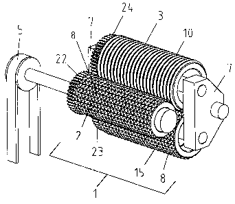
Figure 1 shows a first exemplary embodiment of a device 1
having three embossing rolls, i.e. a first embossing roll 2
that cooperates with a second embossing roll 15 and a
following embossing roll 3, first roll 2 being driven by a
drive mechanism 5. The three embossing rolls are
synchronized by means of gears 22 - 24.
As is symbolically indicated in Figure 3 or 4, the medium 6
that is to be embossed, e.g. a packaging foil 6 that is
metallized with a thin layer of 0.006 mm, is running in the
vertical direction, i.e. from the top to the bottom of the
figures, while the metallized layer is always facing the
driven embossing roll.
The three embossing rolls do not have the same structure.
First, driven embossing roll 2 comprises a number of teeth 8
in the form of truncated pyramids whose sides are parallel
respectively perpendicular to the longitudinal axis of the
embossing roll, as illustrated in Figure 1.
Second embossing roll 15 has a toothing that is identical to
that of first embossing roll 2, i.e. it is also provided
CA 02588167 2007-05-09
(F:\TT\SE\ANNELDUN\27475ENG.DOC Prt: 27.04.2007 SE)
- 5 -
with the teeth 8. This represents a so-called pinup-pinup
configuration.
Third embossing roll 3 is provided with grooves 9 running
around the entire circumference and arranged in parallel to
each other such that teeth 8 of driven embossing roll 2
engage in the grooves. Rings 10 formed between grooves 9 are
also outwardly tapered and flattened such that they engage
between frustopyramidal teeth 8.
In device 20 according to Figure 2, first embossing roll 2
and second embossing roll 15 are represented as having
identical teeth 8. Third embossing roll 4 has longitudinal
grooves 11 forming longitudinal ridges 12 between them that
are also outwardly tapered and flattened like rings 10 in
such a manner that longitudinal grooves 11 and the
longitudinal ridges cooperate with teeth 8 of driven
embossing roll 2.
In device 20, rather than being driven or synchronized with
the driven roll by synchronizing elements such as
gearwheels, for example, the two mating rolls 15 and 4 are
driven by foil 6, see Fig. 3 br 4.
In Figures 3 and 4, devices 30 and 40 are merely composed of
driven roll 2 with teeth 8 and roll 3 with rings 10 and
grooves 9 or roll 4 with longitudinal ridges 12 and grooves
11.
Figure 5 also shows a device 50 of the prior art having two
embossing rolls 2 and 17 with teeth 8 in the pinup-pinup
configuration where driven embossing roll 2 is provided with
a logo, e.g. an "L". At the location of the latter, the
corresponding teeth have been removed.
CA 02588167 2007-05-09
(F:\TT\SE\ANMELDUN\27475ENG.DOC Prt: 27.04.2007 SE) - 6 -
Device 60 of Figure 6 includes driven embossing roll 2 with
teeth 8 and a mating roll 27 having indentations 28 that are
complementary to teeth 8, i.e. a pinup-pindown
configuration. A potential logo would normally be provided
on embossing roll 2.
The devices shown in Figures 1 - 6 are mutually combinable.
Depending on the material of the packaging foil or package,
it may be appropriate to use assemblies of two or three
embossing rolls.
The production of logotypes, emblems and the like,
hereinafter called logos, is e.g. realized by removing,
shortening, or machining teeth on embossing roll 2 having
teeth 8, however in the manner that those teeth do not alter
the surface of the foil. The rings or longitudinal ridges,
respectively, may affect the appearance of the embossing
patterns produced by the embossing roll having teeth.
By means of the embossing roll assemblies it is
simultaneously possible to produce logos and identification
marks by variations of teeth 8 or of rings 10 or of
longitudinal ridges 12, i.e. by altering the height, the
flanks, or the edges of the teeth, rings, or longitudinal
ridges, or by applying patterns to their upper surfaces. For
embossing identification marks the surface of the foil is
altered. Thus, after the embossing process there is a foil
being generally satined and having one logo or several logos
where the surface is not altered and therefore brilliant and
identification marks where the surface is also altered but
otherwise as satined. In certain configurations of the
altered teeth the embossed identification marks have an
appearance that varies according to the viewing angle of the
observer.
CA 02588167 2007-05-09
(F:\TT\SE\ANMELDUN\27475ENG.DOC Prt: 27.04.2007 SE)
- 7 -
In Figure 1 or 2 it is symbolically indicated that second
and third embossing rolls 15 and 3 or 4 interlock with
driven embossing roll 2, but this is not necessarily always
the case. It is also conceivable that the second or the
third embossing roll, respectively, only interlocks or is
only capable of interlocking with the first or the preceding
embossing roll, respectively. Furthermore it may be
advantageous for certain applications to provide more than a
total of three embossing rolls having different surface
structures. Furthermore, both the diameter and the length of
the individual rolls may differ. Also, in addition to the
hard embossing rolls, soft counter-rolls may be used.
For the production of identification marks, it may be
advantageous to provide a forced synchronization of
embossing rolls 2 and 15 having teeth 8 respectively
indentations 28, as it is suggested in the embodiment of
Fig. 1 by gearwheels 22 - 24, the latter being meant to
generally represent synchronizing elements including other
synchronizing means that are known in the art per se, such
as electronic components and the like. A forced
synchronization is also advisable particularly if the
material is subject to strong warping in the embossing
procedure. Depending on the type of material and/or the
drive mechanism, such gearwheels may also be arranged on
both sides of the rolls. Synchronized rolls are generally
positioned highly accurately by suitable auxiliary means.
Embossing identification marks means embossing signs, dots,
patterns, and similar marks for identification purposes that
are produced on-line with satining and the embossing of
logos. More specifically, these identification marks may be
located both in the satined area and in the area of the
logo(s) or on the logo itself, on the driven roll or on a
mating roll. Satining may also be achieved by rolls having
CA 02588167 2007-05-09
(F:\TT\SE\ANMELDUN\27475ENG.DOC Prt: 27.04.2007 SE)
- 8 -
individual pins or needles, which are e.g. individually
controlled, rather than individual teeth, in which case care
must be taken that no through holes are created in the foil.
Preferably, for the present method, marks are used that are
difficult to produce and easy to hide, e.g. in or next to
other marks or next to surface defects, so that they are
hardly noticeable.
In US 6 665 998 Bi to the applicant of the present
invention, also included herein by reference, an embossing
device is disclosed where at least one of the embossing
rolls is contained in an interchangeable unit such that it
is insertable in a bearing mount in a predeterrnined
position. In the embodiment having at least three embossing
rolls, the provision of interchangeable units for individual
rolls or groups of rolls is particularly advantageous a's the
rationalization effect and the ecological advantages are
particularly important in this case.
For the embossing of identification marks, the methods and
the devices according to EP-A-1 437 213 to the applicant of
the present invention may e.g. be used which, as far as
appropriate, are also considered as forming part of the
disclosure. Among the different exemplary embodiments
disclosed in this reference, those according to the Figures
numbered 5, 6, and 8 therein will be selected, i.e. Figures
7 to 9 in the present specification.
In Figures 7 to 9, a surface finish called "microstructure"
herein of the individual teeth and of the tooth bottom of
the driven embossing roll is illustrated. In Figure 7, six
teeth 2S1 to 2S6 are depicted whose microstructures are
shown hatched. The teeth are frustopyramidal with a
rectangular horizontal projection, the lateral edges
CA 02588167 2007-05-09
(F:\TT\SE\ANMELDUN\27475ENG.DOC PZt: 21.04.2007 SE)
- 9 -
extending in parallel respectively perpendicularly to the
longitudinal axis of the roll, and the pyramid tops being
flattened.
Tooth 2S1 has a microstructure 20 on the flattened portion
of the tooth as well as a microstructure 21 on one or both
transversal sides of the tooth, and tooth 2S4 has the same
surface structure 20 and a microstructure 22 on one or both
longitudinal side(s) of the tooth. Tooth bottom ZG may be
provided with a microstructure 23 along the longitudinal
side of the teeth or with a microstructure 24 extending over
certain lengths or with a microstructure 25 extending
transversally thereto.
Tooth 2S2 has a microstructure 26 that extends over the
entire side on one or both of its longitudinal sides, and
tooth 2S3 has a microstructure 27 that extends over the
entire surface of its flattened portion. Teeth 2S5 and 2S6
only have a narrow microstructure 28 extending across the
height of their longitudinal sides or a microstructure 29
extending along their transversal sides. In this manner, it
is understood that a large variety of microstructures can be
applied, thereby creating a correspondingly large variety of
identification patterns on the foil.
In Figures 8A to 8D, some examples of possible straight or
curved microstructures on top and on the sides of the teeth
are indicated at a larger magnification. In Figure 8A, a
cross-section of a positive grid structure is illustrated,
the individual ridges 30 being arranged at intervals of some
m. This structure may be used for any one of
microstructures 20, 21, 28, or 29 and also on the tooth
bottom, e.g. for microstructures 23, 24, or 25.
CA 02588167 2007-05-09
(F:\TT\SE\ANMELDUN\27475ENG.DOC Prt: 27.04.2007 SE)
- 10 -
In Figure 8B, a cross-section of a negative grid structure
is schematically indicated, recesses 31 also being arranged
at intervals of some 100 nm to some m.
In Figure 8C, a possible positive microstructure formed of
grid-like, curved ridges 32 is schematically indicated in a
perspective view.
In Figure 8D, a possible negative microstructure formed of
grid-like, curved grooves 33 is schematically indicated in a
perspective view. This structure is e.g. appropriate for use
in microstructure 24 or 25.
It becomes apparent from these few examples that a very
large range of variation both of the microstructures,
respectively of the arrangement of these microstructures on
the individual teeth and on the tooth bottom or only on the
tooth bottom alone, and of the kind of the microstructures
themselves is possible. This depends on the current state of
the art with regard to the production of such structures,
the production of microstructures being also applied
particularly in the manufacture of electronic chips and
known from this field. In such fine microstructures, the
application of suitable methods such as lacquer or etching
techniques plays an important role.
The teeth of Figure 9 are provided both with a
macrostructure and a microstructure. In this regard, the
term "macrostructure" designates a modification of the tooth
geometry in the range of some 10 .m up to 600 m while the
microstructure refers to the modification of the surfaces or
bottoms of the teeth.
Figure 9 illustrates three geometrically unmodified teeth
2S1, 2S4, and 2S6, however with microstructures as in Figure
CA 02588167 2007-05-09
(F:\TT\SE\ANMELD'JN\27475ENG.DOC Prt: 27.04.2007 SE)
- 11 -
7, as well as teeth 2M1, 2M2, and 2M3 where the "M" stands
for macrostructure. Tooth 2M1 exhibits a greater amount of
flattening than a regular tooth such as 2S1, the flattened
portion being provided with a microstructure 20.
Tooth 2M2 only has a larger amount of flattening and is
otherwise unmodified, whereas tooth 2M3 is cut in half in
its width. Of course, teeth 2M2 and 2M3 may be provided with
microstructures as well. Again, in the example according to
Figure 9, the tooth bottom may be machined and may have the
same microstructure 23 as in Figure 7 and a microstructure
25.
An even greater variety of possible modifications of teeth
results from the illustration of Figure 9, thereby providing
a very large variety of embossing patterns. Alternatively,
only the structures on the tooth bottom may be used for
embossing alone.
In the pinup-pindown configuration, it is not only possible
to make the indentations shallower, in analogy to the
flattened teeth, but also to provide complementary
macrostructure's and/or microstructures in the indentations.
In Fig. 10, another possible embossing station is
illustrated that consists of two roll pairs that are driven
by the same drive mechanism while the pairs, i.e. the
embossing stations, are each synchronized internally.
First embossing station 70 comprises two smooth metal rolls
71 and 72, first roll 71 being driven directly and provided
on its surface with a raised embossing zone L. The symbol
"L" stands for identification marks of any kind that may be
individual dots or signs or of a group of signs, dots, or
the like. It is understood that several embossing zones may
CA 02588167 2007-05-09
(FI\TT\SE\ANMELDUN\27475ENG.DOC Prt: 27.04.2007 SE)
- 12 -
be provided on the roll too. Mating roll 72 is also made of
metal, e.g. of steel, and has no surface structure.
Second embossing station 80 comprises two structured
embossing rolls as they are known from US 7 147 453 B2, in
this case a directly driven roll 81 having projecting teeth
82 and a roll 83 having rings 84, which are synchronized
with one another or contained in a common enclosure. This
second roll pair is intended for satining the foil according
to the known state of the art and if occasion arises
providing it with a logo or a plurality of logos.
This means that the foil that is to be embossed is fed from
a storage roll to the first roll assembly, the
identification marks are embossed, and then the foil passes
to the second roll assembly. Care must be taken, however,
that the identification marks embossed in the first roll
assembly are not impaired in the second roll assembly and
therefore, on driven roll 81, the teeth are removed at the
location or locations where the embossed identification mark
or marks impinge on the roll so that the foil is not re-
embossed in gap B.
In the embodiment variant according to Figure 10A, foil 6 is
first satined in embossing station 80A and subsequently
provided in second embossing station 70 with one or a
plurality of identification mark(s) that are hidden in the
satined foil.
The embossing stations may have a common or a sequential
drive mechanism or two drive mechanisms and may be arranged
in one housing or in two housings.
Now, one of the inventive ideas is to produce, by means of
the known devices having modified individual teeth, rings,
CA 02588167 2007-05-09
(F:\TT\SE\ANMELDUN\27475ENG.DOC Prt: 27.04.2007 SE)
- 13 -
or longitudinal ridges on embossing rolls or by providing
suitable structures on an otherwise smooth roll, a
particular arrangement of identification marks represented
by an array of dots, signs, or the like that can be
recognized and thus identified in the authentication
procedure. To this end, e.g. a checkerboard-like pattern or
another reproducible pattern is produced by means of
individual teeth, rings, longitudinal ridges, or suitable
structures on an otherwise smooth roll that are modified
according to a particular pattern, and in this array of dots
deviating from the ordinary points that are created by
satining, one or a plurality of defined geometrical areas
are selected in which the array of identification marks is
authenticated.
In order to be able to establish a demarcation between the
ordinary satin-finished dots and the modified ones,
reference will be made to the term "satining" as it has been
defined in the introduction.
With regard to the packaging materials, reference will be
made to the introduction of the description as well. The so-
called inliners, i.e. the packaging foils that are wrapped
around objects to be packaged like cigarettes and either
consist of metal foils or of metallized foils, have the
following properties:
- They serve as elegant packaging materials,
- they may not contract, curl, or twist in the transversal
direction because of the resulting folds and consequent
disturbances in the following packaging machines,
CA 02588167 2007-05-09
(F:\TT\SE\ANMELDUN\27475ENG.DOC Prt: 27.04.2007 SE)
- 14 -
- the mat optical effect - the satined effect - is achieved
by embossing small indentations that reflect the light
diffusely.
The size of the elevations is chosen such that they are
hardly visible as such by the eye. Generally, elevations are
produced at intervals smaller than 0.5 mm. The height of the
elevations is therefore coarsely half this value, i.e.
smaller than 0.25 mm.
The plastic foils are the so-called wrappers that are
wrapped around containers such as cigarette packets. These
foils, which may be single or multilayer foils, are provided
with identification marks and satin-finished in the same
embossing roll assemblies and may also be provided with
logos. The identification marks and/or logos may also be
embossed holograms.
Preferably, within the limits of satining specified above,
one or several arrays of dots or similar marks are embossed
by modified teeth, rings, or ridges or the like, and a
certain number of marks in a previously defined area or in
several areas thereof are selected by electronic means in
order to relate and compare them to the arrays, patterns, or
specifically arranged dots on the packaging foil or the
packaging material to be authentified by means of an image
processing method.
Figure 11 schematically illustrates a grid on a foil as it
is obtained during satining, i.e. regularly arranged
indentations S that have been created by the described
methods and devices for satining. In addition,
identification marks M are created, i.e. differently
designed indentations that have been created by the
CA 02588167 2007-05-09
(F:\TT\SE\ANMELDUN\27475ENG.DOC Prt: 27.04.2007 SE)
- 15 -
embossing of micro- or macrostructures. Figure 12 shows an
enlarged detail of Fig. 11.
In one possible exemplary embodiment of the method, the
surface of a packaging foil provided with identification
marks is recorded by a video camera. However, the method of
the invention also allows other imaging methods. In order to
perform a comparison of the template having a specific
pattern, e.g. a checkerboard-like template, with the image
recorded by the video camera, an image processing technique
based on so-called template matching is applied.
The statistic relationship between the marks of the template
and those of the embossed identification mark determined by
this method is used as a measure of the similarity between
the template and the embossed pattern and therefore forms
the basis of the decision regarding authenticity. In
practice it has been found that an authentication that is
sufficiently safe for many purposes can be achieved by
empirically specifying a minimum level of the processing
signal against noise.
The reliable and quick authentication, hitherto impossible
to achieve, of identification marks in the satined area or
in the logo zone that are invisible or only barely visible
by the eye, may be refined by alternative methods used in
automatic image processing and known to those skilled in the
art, such as e.g. gray scale correlation, and by the
application of suitable software algorithms.
According to the invention, reading of the patterns may also
be achieved directly through the outer packaging e.g. of
cardboard by means of optical imaging devices using daylight
or a spectrally appropriate lighting source. To this end,
the wavelength of the lighting source should be selected
CA 02588167 2007-05-09
(F:\TT\SE\ANMELDUN\27475ENG.DOC Prt: 27.04.2007 SE)
- 16 -
such that the radiation is reflected by the metallic side of
the packaging foil while passing through the remaining parts
of the package.
All these image processing methods have in common that a
specified pattern is produced in a specified area on a
template and this template serves both for producing the
corresponding pattern on the embossing roll -- through the
modification of teeth, etc. -- and for determining the
degree of similarity of the produced foil and of the
template.
The selection of an area facilitates or accelerates the
method, respectively, but it is not always required.
Moreover, in the suggested method, relatively simple
modifications on the teeth are sufficient as the detection
of differences in brightness on the reflecting embossed
materials is principally utilized.
Furthermore, due to the easy electronic detection of the
object that is to be authenticated, a quick and reliable
examination thereof is also possible from a distance by
remote inquiry.
Based on the methods described above, it may be advantageous
to combine the latter with other authentication methods that
are known in the art per se if an even higher degree of
safety is required.
- - - - -