Note: Descriptions are shown in the official language in which they were submitted.
CA 02588490 2007-05-14
UTILITY PAL v_:NT APPLICTION
DOCKET NO. 03269.0134111
FLOORING PROFILE
Field of the Invention
[00011 The present invention pertains to a flooring profile. More
specifically, the invention is a flooring profile for use with a hardwood or
engineered hardwood flooring board.
Background of the Invention
[0002] Hardwood flooring has become a very popular choice in floor
coverings. Traditional hardwood floors are made from a variety of wood planks
and are placed in side-by-side relation to each other with the side edges
being
engaged with a tongue and groove arrangement. in order to secure the
floorboard to the subfloor, nails are driven at an angle through a portion of
the
tongue of the plank and into the subfloor below.
[0003] One common substitute for hardwood flooring is laminate flooring_
Laminate flooring is made to look like hardwood, but is easier to install and
less
expensive. Laminated flooring members typically comprise a decorative surface
layer, a core, a balancing backing layer, and a wear layer, which are bonded
together. The decorative surface layer can be made of a resin, such as, for
example a melamine/aluminum oxide based resin. The decorative surface layer
is typically bonded to a moisture resistant core that can be formed from, for
example, a wood composition.
[0004] Conventional cores are made of high or medium density fiberboard
that is typically saturated in resins to make them extremely hard. This allows
the
laminate flooring members to be cut with an edge profile, such as a tongue and
complementary groove, as desired, for ease of installation.
[0005] The balancing backing layer is applied to the underside of the core
to help stabilize the laminate flooring member and to act as another barrier
against moisture entering the laminate flooring member from below. Most
manufacturers saturate the backing layer with resin to resist moisture
intrusion
1
CA 02588490 2007-05-14
7' =
UTILITY PAi ENT APPL1CTION
DOCKET NO. 03269.0134U1
and to make the balancing backing layer more dimensionally stable. In
conventional construction, laminate flooring members formed with a balancing
backing layer are not typically glued directly to the sub floor_
100061 The wear layer is applied to provide protection and stain
resistance
to protect the top of the laminate flooring member, The wear layer is
typically
clear so that the aesthetic appearance of the decorative layer, including any
color
and/or printed image, is not obscured by the overlying wear layer. However,
while great care is taken to ensure that the laminate flooring member looks
like
real hardwood flooring, any damage to the wear layer makes it evident that it
is
not true hardwood flooring.
Nom Another alternative to hardwood flooring is engineered
hardwood.
An engineered hardwood flooring board is conventionally constructed with an
upper layer, a middle layer and a lower layer. The upper layer is typically
formed
of conventional hardwood flooring material. The middle layer is conventionally
formed of a non-hardwood material, such as medium density fiberboard, high
density fiberboard, particle board, plywood and the like. The lower layer can
also
be formed from a hardwood material similar to the upper layer, or it can be
formed from a non-hardwood material that has specially selected properties,
such
as water resistance or rigidity.
[0008] The upper layer of the engineered hardwood flooring board is
formed of hardwood to give the board the appearance of conventional hardwood
flooring and to enable the engineered hardwood flooring board to be sanded
when damaged, similarly to a hardwood-only board.
[00091 Further, the use of alternative material as the middle
layer, or core
of the board, greatly increases the dimensional stability of the board, which
,
allows the production of engineered hardwood flooring boards that are longer
and
wider than conventional hardwood flooring boards.
7
CA 02588490 2007-05-14
UTILITY PATENT APPLICTION
DOCKET NO. 03269.01341D1
[00101 The material in the middle layer can be formed or milled precisely
prior to assembly into the engineered hardwood flooring board, which results
in
boards with tight tolerances that can easily be engaged with one another to
form
the flooring surface. In one example, similar to conventional hardwood
flooring
boards, engineered hardwood flooring boards can comprise a tongue and a
complementary groove positioned on and extending along opposite sides of the
board. Alternatively, the boards can be secured to one another using a snap-
fit
profile, similar to those used in the laminate flooring industry.
(00111 Conventional method of installation may cause some installation
issues when the engineered hardwood flooring boards are engaged with a
traditional tongue and groove connection. Notably, due to the increased
density
of the core material used in the middle layer portions of the core may be
displaced when a nail or other fastener is driven into the top portion of the
tongue, which causes a portion of the surface of the engineered hardwood
flooring board to visibly protrude or bubble, In fact, this phenomenon often
occurs in conventional hardwood flooring boards. What is needed is a flooring
board and a method of installing an engineered hardwood flooring board that
alleviates the problem of surface bubbling_
Summary
In one embodiment, the present invention pertains to a flooring panel
comprising opposed pairs of substantially parallel side edges, a tongue
connector
member, and a groove connector member. In one aspect, the tongue connector.
member extends along one side edge and the groove connector member extends
along the opposed side edge.
In another aspect, the tongue connector member and the groove
connector member are configured to cooperatively couple with each other such
that portions of the coupled flooring panels are positioned in abutting
relationship.
In an exemplary aspect, when respective first and second flooring panels are
coupled to each other along adjacent side edges, a distal end of the upper
3
CA 02588490 2007-05-14
UTILITY PATENT APPLIC'T1ON
DOCKET NO. 03269.0134U1
shoulder of the tongue connector member of the first flooring panel contacts
or
abuts a distal end of an upper lip of the groove connector member of the
second
flooring panel.
Other apparatus, methods, and aspects and advantages of the invention
will be discussed with reference to the Figures and to the detailed
description of
the preferred embodiments.
Brief Description of the Drawings
[0012] The accompanying drawings, which are incorporated in and
constitute a part of this specification, illustrate several aspects described
below
and together with the description, serve to explain the principles of the
invention.
Like numbers represent the same elements throughout the figures.
[0013] Fig. 1 is a cross-sectional view of one embodiment of a flooring
panel according to the present invention showing a tongue connector with a
displacement cavity and a fastening recess.
[0014] Fig. 2A is a partial cross-sectional view of the flooring panel of
Fig.
1, showing a groove connector member.
[00151 Fig. 2B is a partial cross-sectional view of the flooring panel of
Fig.
1. showing the tongue connector member.
[0016] Fig. 3 is a partial cross-sectional view of two adjacent flooring
panels of the embodiment of Fig. 1, showing the flooring panels in an engaged
position_
[0017] Fig. 4 is a cross-sectional view of an alternate embodiment of a
flooring panel according to the present invention_
4
CA 02588490 2007-05-14
UTILITY PAIENT APPLICTION
DOCKET NO. 03269.01341)1
[0018] Fig. 5A is a partial cross-sectional view of the flooring panel of
Fig.
4, showing a groove connector member.
[0019] Fig. 5B is a partial cross-sectional view of the flooring panel of
Fig.
4, showing the tongue connector member.
[0020] Fig. 6 is a partial cross-sectional view of two adjacent flooring
panels of the embodiment of Fig. 4, showing the flooring panels in an engaged
position.
Detailed Description of the Invention
]0021] The present invention can be understood more readily by reference
to the following detailed description, examples, drawings, and claims, and
their
previous and following description. However, before the present devices,
systems, and/or methods are disclosed and described, it is to be understood
that
this invention is not limited to the specific devices, systems, and/or methods
disclosed unless otherwise specified, as such can, of course. vary. It is also
to
be understood that the terminology used herein is for the purpose of
describing
particular aspects only and is not intended to be limiting_
[0022] The 'following description of the invention is provided as an
enabling
teaching of the invention in its best, currently known embodiment. To this
end,
those skilled in the relevant art will recognize and appreciate that many
changes
can be made to the various aspects of the invention described herein, while
still
obtaining the beneficial results of the present invention. It will also be
apparent
that some of the desired benefits of the present invention can be obtained by
selecting some of the features of the present invention without utilizing
other
features. Accordingly, those who work in the art will recognize that many
modifications and adaptation to the present invention are possible and can
even
be desirable in certain circumstances and are a part of the present invention.
Thus, the following description is provided as illustrative of the principles
of the
present invention and not in limitation thereof.
_ _ CA 02588490 2007-05-14
_ . . .
UTILITY PA1 eNT APPLICTION
DOCKET NO. 03269.0134U1
[0023] As used herein, the singular forms "a," "an" and "the" include
plural
referents unless the context clearly dictates otherwise. Thus, for example,
reference to a "flooring panel" includes aspects having two or more such
flooring
panels unless the context clearly indicates otherwise.
[0024] Ranges can be expressed herein as from "about" one particular
value, and/or to "about" another particular value. When such a range is
expressed, another aspect includes from the one particular value and/or to the
other particular value. Similarly, when values are expressed as
approximations,
by use of the antecedent "about," it will be understood that the particular
value
forms another aspect. It will be further understood that the endpoints of each
of
the ranges are significant both in relation to the other endpoint, and
independently of the other endpoint.
[0025] As used herein, the terms "optional" or "optionally" mean that the
subsequently described event or circumstance may or may not occur, and that
the description includes instances where said event or circumstance occurs and
instances where it does not.
[0026] The present invention may be understood more readily by reference
to the following detailed description of preferred embodiments of the
invention
and the examples included therein and to the Figures and their previous and
following description.
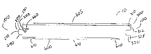
[0027] In one aspect, the present invention is a flooring panel 10 that
comprises opposed pairs of substantially parallel side edges 100. In one
aspect,
the flooring panel comprises a tongue and groove edge profile. In this aspect,
there is a tongue connector member 200 extending along one side edge of at
least one of the opposed pairs of side edges 100.
[0028] The tongue connector member 200 itself comprises an upper
shoulder 210 and a lower shoulder 220 and defines a displacement cavity 260
6
CA 02588490 2007-05-14
UTILITY PATENT APPLICTION
DOCKET NO. 03269.0134U1
therein. In yet another aspect, the tongue connector member has a top tongue
contact surface 230, a bottom tongue contact surface 240 and a distal
peripheral
surface 250 that extends between the respective top and bottom tongue contact
surfaces. In another aspect, a portion of the tongue connector member defines
a
fastening surface 202, which is configured to accept a variety of conventional
fasteners, such as, for example and not meant to be limiting, one or more
nails,
staples, tacks, and the like. In one aspect, the fastening surface 202 is
defined
thereon the tongue connector member substantially beneath the displacement
cavity 260. In this sense, beneath means closer to the bottom surface of the
flooring panel in relation to the displacement cavity. In another aspect, the
fastening surface is defined thereon the upper shoulder 210 substantially
beneath
the displacement cavity. In yet another aspect, the fastening surface is
defined
thereon a portion of a surface of the displacement cavity.
[0029] A groove connector member 300 is defined in one side edge of at
least one of the opposed pairs of side edges. As illustrated in Fig. 1, the
groove
Connector member 300 comprises an upper lip 310 and a lower lip 320. One
skilled in the art would appreciate that the tongue connector member and the
groove connector member are configured to cooperatively couple with each
Other.
[I:1030] In another aspect of the invention, the groove connector member
300 has an upper groove contact surface 330, a lower groove contact surface
340 and a wall surface 350 that extends between the respective top and bottom
groove contact surfaces.
[0031] In another aspect, the tongue connector member 200 and the
groove connector member 300 are configured to cooperatively couple with each
other such that a distal end 212 of the upper shoulder 210 of a first flooring
panel
contacts a distal end 312 of the upper lip 310 of a second flooring panel upon
coupling of the respective tongue and groove connector members of the
respective first and second flooring panels to each other along adjacent side
edges. In this fashion, the adjacent flooring panels have the perception of
being
7
CA 02588490 2007-05-14
UTILITY PATENT AFFLICTION
DOCKET NO. 03269.0134UI
joined when looking at the flooring system. As one skilled in the art can
appreciate and as illustrated in the figures, the distal end 312 of the upper
lip of
the second flooring panel and the distal end 212 of the upper shoulder of the
first
flooring panel may be beveled such that, when the adjacent flooring panels are
coupled, the seam between the two flooring panels forms a recessed channel
400. A benefit of this feature is to disguise imperfections in the flooring
panels to
the extent that the uppermost surfaces of the adjacent panels may not be
perfectly coplanar.
[0032] The tongue connector member and the groove connector member
may also be configured to cooperatively couple with each other such that a
distal
end 222 of the lower shoulder 220 of the first flooring panel is spaced from
the
distal end 328 of the lower lip 320 of the second flooring panel upon coupling
of
the respective tongue and groove connector members of the respective first and
second flooring panels to each other along adjacent side edges 100_ As
illustrated in Fig. 3, this clearance helps to ensure that the visible joint
on the top
surface 605 of the adjoining flooring panels is substantially closed, i.e.,
portions
of the distal ends 212, 312 of the respective adjoining upper shoulder and
upper
lip are placed in an abutting relationship.
[0033] In a further aspect, the tongue connector member and the groove
connector member are configured to cooperatively couple with each other such
that a portion of the distal peripheral surface of the tongue connector member
of
the first flooring panel is spaced from a portion of the wall surface 350 of
the
groove connector member of the second flooring panel upon coupling of the
respective tongue and groove connector members of the respective first and
second flooring panels to each other along adjacent side edges. The space
provides additional clearance to enable the joint to completely close in the
event
that an obstruction, such as a splinter, or an adhesive, becomes trapped
between
the distal peripheral surface 250 of the tongue connector member 200 and the
wall surface of the groove connector member 300. Further, in one aspect, in a
coupled position, the distal peripheral surface of the tongue connector member
of
the first flooring panel, the wall surface of the groove connector member and
8
CA 02588490 2007-05-14
UTILITY l'AiENT APPLICTION
DOCKET NO. 03269,0134U1
portions of the respective upper and lower groove contact surfaces define a
longitudinally extending pocket 500.
[00341 As mentioned herein above, the fastening surface is provided
beneath the displacement cavity of the tongue connector member, such that a
conventional fastener 20 may engage the flooring member with a portion of the
subfloor or other installation surface. In conventional flooring profiles the
placement of the fastener on a portion of the tongue connector member may
cause an obstruction when the tongue connector member is attempted to be
placed into operative engagement with the groove connector member, which
results in the floor panels being placed in an undesirable spaced
relationship.
This issue is addressed in one aspect of the present invention where the
fastening surface defines a recess 205 that is configured to receive a
fastener. In
one aspect, the recess comprises a recess axis AR that intersects the bottom
surface of the flooring panel.
[0035] Where the fastening surface defines a recess, the tongue connector
member may comprise one recess or a plurality of recesses_ The recess may be
shaped to engage an individual fastener or it may extend longitudinally
substantially parallel to the upper shoulder of the tongue connector member.
In
yet another aspect, the recess 205 extends longitudinally substantially the
length
of the flooring panel_ It is contemplated that the recess can be spaced along
the
longitudinal length of the flooring panel. Further, the recess can be spaced
from
the ends of the flooring panel.
100361 As one skilled in the art can appreciate, when a fastener 20 is
driven therethrough the fastening surface 202 and into the installation
surface, a
portion of flooring panel adjacent the fastening surface will be displaced_ In
conventional flooring panels, this displacement can cause material to expand
and
may cause the top surface 605 of the flooring panel to exhibit a visible
blemish or
bubble. This issue is solved by the placement of the displacement cavity 260.
The displacement cavity is designed to absorb the displaced material resulting
from expansion caused by the fastener 20.
9
CA 02588490 2007-05-14
_ _ .
ITTILITY PATENT APPLICTION
DOCKET NO. 03269.0134U1
[0037] In one aspect, a portion of the displacement cavity 260
forms a
deformable surface 262 designed to deform and occupy a portion of the
displacement cavity upon insertion of a fastener 20 into the fastening
surface. In
another aspect, a portion of the displacement cavity forms a non-deformable
surface 264 positioned adjacent the top surface of the flooring panel. As one
skilled in the art can appreciate, the non-deformable 264 surface is not
designed
to deform upon insertion of the fastener, thereby preventing blemishing or
bubbling of the top surface of the flooring panel. In one exemplary aspect,
the
deformable surface is spaced from and underlies the non-deformable surface.
(00381 In another aspect, the displacement cavity comprises a
displacement axis AD which forms an acute angle a relative to the recess axis.
in
yet another aspect, the displacement axis is substantially parallel to the top
surface 605 of the flooring panel.
[00391 In some instances, as the fastener 20 extends therethrough
the
tongue connector member and exits through the bottom surface 600 of the
flooring panel, it has the potential of splintering either the bottom surface
of the
flooring panel or the top surface of the installation surface, or both. The
splinters
may cause the flooring panel to lie on the installation surface in an uneven
fashion. To counter this problem, in one aspect, the bottom surface of the
flooring panel defines a trough 610. The trough 610 is configured to provide a
relief space for the formed splinters. In another aspect, at least a portion
of the
trough intersects the recess axis, thereby substantially intersecting the path
of the
fastener. In yet another aspect, the trough extends longitudinally
substantially
parallel to the tongue connector member. In this aspect, the trough may or may
not extend substantially the longitudinal dimension of the flooring panel.
[0040] As one skilled in the art can appreciate, the flooring panel
of the
present invention may comprise a hardwood material, or it may comprise a
plurality of materials in a laminate structure. In one aspect, the flooring
panel
comprises a wood based core material 700 comprising a ground wood product
CA 02588490 2007-05-14
= UTILITY PA1 ENT APPLICTION
DOCKET NO. 03269.0134U1
and a binding agent unified to form a cured composite. As such, the core
material 700 may comprise medium density fiberboard ("MDF"), high density
fiberboard ("HDF"), or any other conventional wood based product. In yet
another aspect, the respective tongue and groove connector members are
formed from the core material.
[0041] When the flooring panel is a laminate structure, in one
aspect, it
comprises a decorative layer 800 connected to an upper surface of the core
material. The decorative layer 800 may comprise a melamine sheet, as in
conventional laminate structures. It may also comprise a hardwood material, as
in engineered hardwood flooring panels. However, it may also comprise any
other conventional substance used for decorative layers in laminate flooring
boards.
[0042] In another aspect, the flooring panel comprises a bottom
support
layer 900 connected to a lower surface of the core material. If the flooring
panel
comprises a trough 610 defined in its bottom surface, the trough may be
defined
therein bottom surface of the bottom support layer 900.
[0043] In still a further aspect, the invention is a method for
making the
flooring panel described herein. The method comprises the steps of: providing
at
least one plank of flooring material; forming the aforementioned tongue
connector
member into and extending along at least one of the side edges of the pair of
opposed side edges to include forming the displacement cavity; and forming the
aforementioned groove connector member into and extending along a side edge
opposite of the tongue.
[0044] In another aspect, the method comprises forming the
aforementioned recess in the fastening surface. As mentioned herein above, the
recess may comprise a plurality of recesses. Additionally, the method may also
comprise forming the trough in the bottom surface of the flooring panel.
11
CA 02588490 2007-05-14
UTILITY PA i'ENT APPLICTION
DOCKET NO. 03269.0134U1
100451 In yet another aspect, with respect to forming a flooring panel
comprising a core material, the method may also comprise connecting a
decorative layer to an upper surface of the core material. The method may also
comprise connecting a bottom support layer to a lower surface of the core
material_ As one skilled in the art can appreciate these additional steps may
be
executed in any conventional manner.
[00461 In one aspect, the invention is a method of assembling a floor using
a plurality of the flooring panels described herein. The method comprises the
steps of:
a) providing a plurality of planks of the aforementioned flooring panels;
b) placing a first one of the planks on an installation surface or
subfloor, which substantially underlies the bottom surface of the plank;
c) driving at least one fastener through the fastening surface of the
tongue connector member such that a portion of the fastener penetrates
into the installation surface, and such that a portion of the deformable
surface of the displacement cavity deforms into the displacement cavity;
d) placing a second plank on the installation surface such that the
groove connector member of the second plank cooperatively engages the
tongue connector member of the first plank; and
e) repeating steps (c) and (d) for additional planks until the total
number of desired planks is achieved.
[0047j The preceding description of the invention is provided as an
enabling teaching of the invention in its best, currently known embodiment. To
this end, those skilled in the relevant art will recognize and appreciate that
many
changes can be made to the various aspects of the invention described herein,
while still obtaining the beneficial results of the present invention. It will
also be
apparent that some of the desired benefits of the present invention can be
obtained by selecting some of the features of the present invention without
utilizing other features_ The corresponding structures, materials, acts, and
equivalents of all means or step plus function elements in the claims below
are
12
CA 02588490 2014-04-09
intended to include any structure, material, or acts for performing the
functions in
combination with other claimed elements as specifically claimed.
(00481 Accordingly, those who work in the art will recognize that many
modifications and adaptations to the present invention are possible and can
even
be desirable in certain circumstances and are a part of the present invention.
Thus, the preceding description is provided as illustrative of the principles
of the present invention and not in limitation thereof. It is intended that
the
specification and examples be considered as exemplary only, with a true scope
and spirit of the invention being indicated by the following claims.
13