Note: Descriptions are shown in the official language in which they were submitted.
CA 02588648 2012-09-14
1
HEATING INSTALLATION AND HEATING METHOD
FIELD OF THE INVENTION AND PRIOR ART
The present invention relates to a heating installation comprising a first
circuit
containing a first medium, a second circuit containing a second medium, and a
first heat
generating arrangement in the form of a heat pump arranged in the first
circuit for heating the
first medium in the first circuit, and a method for heating a second medium in
a second
circuit, heat generation to a first medium in a first circuit being
performable by means of at
least one first heat generating arrangement in the form of a heat pump. The
invention also
relates, to the use of a heating installation according to the invention for
providing tap hot-
water.
A heating installation comprising a first circuit containing a first medium, a
second
circuit containing a second medium, and a first heat generating arrangement in
the form of a
heat pump arranged in the first circuit for heating the first medium in the
first circuit is
previously known from the patent document WO 00/32992 Al. This previously
known heating
installation comprises two or three heat transferring devices in the form of
heat exchangers
arranged in a second circuit comprising a second medium, for instance in the
form of tap hot-
water, in order to transfer heat from a first medium in a first circuit to the
second medium in
the second circuit. A first heat generating arrangement in the form of a
heating boiler and a
second heat generating arrangement in the form of a heat pump are arranged in
said first
circuit in order to generate heat to the first medium in the first-circuit. By
means of said heat
transferring devices, it will be possible to gradually heat the second medium
in the second
circuit to a desired end temperature. This previously known heating
installation makes it
possible to use, to a great extent, the heat pump as a primary energy source
in the heating
installation for heating of tap hot-water as well as radiators, whereas the.
heating boiler needs
to be in operation only at relatively high load in order to satisfy the
prevailing heating
demands, which till reduce the operating costs of the heating installation.
SUMMARY OF THE INVENTION
According to the invention, there is provided a heating installation
comprising a first
circuit containing a first medium, a second circuit containing a second
medium, and a first
heat generating arrangement in the form of a heat pump arranged in the first
circuit for
heating the first medium in the first circuit, and a method for heating a
second medium in a
second circuit, heat generation to a first medium in a first circuit being
performable by means
CA 02588648 2012-09-14
2
of at least one first heat generating arrangement in the form of a heat pump.
The inventive
solution implies that a heat exchanger connected between the condenser and the
expansion
valve of a first heat pump is used in order to transfer heat from the working
medium of the
heat pump to a third medium in a third circuit, a further heat pump, here
denominated second
heat pump, being arranged for heating the second medium in the second circuit
by absorbing
heat energy from the third medium in the third circuit. The second medium in
the second
circuit is preferably water in-tended to be heated in order to provide tap hot-
water. Said
heating by means of the second heat pump suitably constitutes a final heating
step in a
process for heating tap hot-water to a desired temperature, i.e. a final
heating of the tap hot-
water.
According to an aspect of the invention, there is provided a heating
installation
comprising a first circuit containing a first medium, a second circuit
containing a second
medium, and a first heat generating arrangement in the form of a heat pump,
here
denominated first heat pump, arranged in the first circuit for heating the
first medium in the
first circuit, characterized in that the heating installation further
comprises: a third circuit
containing a third medium, a heat exchanger, here denominated first heat
exchanger, which
is arranged in the third circuit and which is connected between a condenser
and an
expansion valve of the first heat pump in order to transfer heat from the
working medium of
the first heat pump to the third medium in the third circuit, and a second
heat generating
arrangement in the form of a heat pump, here denominated second heat pump,
arranged for
heating .the second medium in the second circuit by absorbing heat energy from
the third
medium in the third circuit.
According to a further aspect of the invention, there is provided use of a
heating
installation as described above for providing tap hot-water, the second medium
in the second
circuit consisting of water that is heated in order to provide said tap hot-
water.
According to another aspect of the invention, there is provided a method for
heating a
second medium in a second circuit, heat generation to a first medium in a
first circuit being
performable by means of at least one first heat generating arrangement in the
form of a heat
pump, here denominated first heat pump, characterized in that heat transfer
from the working
medium of the first heat pump (2) to a third medium in a third circuit (K3) is
performed by
means of a heat exchanger (40) connected between a condenser (2d) and an
expansion
valve (2f) of the first heat pump, and that heating of the second medium in
this second circuit
(1<2) is performed by means of a second heat generating arrangement in the
form of a heat
CA 02588648 2012-09-14
2a
pump, here denominated second heat pump, by absorbing heat energy from the
third
medium in the third circuit.
With the inventive solution, surplus heat of the working medium of the first
heat pump
is used in order to give the second medium in the second circuit a temperature
increase
when the first heat pump is in operation. By utilizing said surplus heat of
the working medium
of the heat pump in the heating of the second medium, instead of wasting it,
an increase of
the efficiency of the heat pump is obtained.
CA 02588648 2007-05-18
WO 2006/057594 PCT/SE2005/001738
3
According to a preferred embodiment of the invention, the heat-
ing installation comprises a further heat exchanger, here de-
nominated second heat exchanger, arranged in the third circuit
in series with the first heat exchanger in order to transfer heat
from the third medium in the third circuit to the second medium
in the second circuit. This heat transfer suitably constitutes a
first initial heating step in a process for heating tap hot-water to
a desired temperature, i.e. a preheating of the tap hot-water.
Also in this heating step, surplus heat of the working medium of
the first heat pump is used in order to give said second medium
a temperature increase when the first heat pump is in operation,
whereby the energy required in the subsequent heating step or
the subsequent heating steps in order to increase the tempera-
ture of the second medium to the desired end temperature is re-
duced correspondingly. By means of the second heat ex-
changer, it will also be possible to use the heat energy in the
third circuit for heating the second medium in the second circuit
without requiring that the second heat pump is in operation.
According to another preferred embodiment of the invention, the
heating installation comprises a further heat exchanger, here
denominated third heat exchanger, arranged in the third circuit
in series with the first heat exchanger in order to transfer heat
from a fourth medium, for instance ambient air, to the third me-
dium in the third circuit. This third heat exchanger may assist
the first heat exchanger and give a supplementary heat contri-
bution to the second heat pump, and whenever applicable to the
second heat exchanger. The third heat exchanger may also be
used in order to give heat energy to the second heat pump, and
whenever applicable to the second heat exchanger, when the
first heat pump is not in operation.
Further preferred embodiments of the inventive heating installa-
tion and the inventive method will appear from the dependent
claims and the subsequent description.
WO 2006/057594 CA 02588648 2007-05-184
PCT/SE2005/001738
The invention also relates to the use of the inventive heating in-
stallation for providing tap hot-water, in which case the second
medium in the second circuit is water that is heated in order to
provide said tap hot-water.
BRIEF DESCRIPTION OF THE DRAWINGS
With reference to the enclosed drawings, a more specific de-
scription of embodiment examples of the invention will follow
hereinbelow. It is shown in:
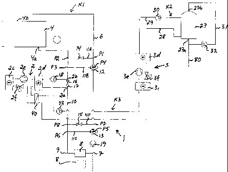
Fig 1 a schematic illustration of a heating installation accord-
ing to a first embodiment of the present invention,
Fig 2 a schematic illustration of a heating installation accord-
ing to a second embodiment of the present invention,
Fig 3 a schematic illustration of a heating installation accord-
ing to a third embodiment of the present invention,
Fig 4 a schematic illustration of a heating installation accord-
ing to a fourth embodiment of the present invention,
Fig 5 a schematic illustration of a heating installation accord-
ing to a fifth embodiment of the present invention, and
Fig 6 a schematic illustration of a heating installation accord-
ing to a sixth embodiment of the present invention.
DETAILED DESCRIPTION OF PREFERRED EMBODIMENTS
The inventive heating installation 1 comprises at least three cir-
cuits K1, K2, K3 for three separate media, namely a first circuit
K1 containing a first medium, e.g. water, a second circuit K2
comprising a second medium, e.g. tap hot-water, and a third cir-
WO 2006/057594 CA 02588648 2007-05-185
PCT/SE2005/001738
cuit K3 containing a third medium, e.g. water. Different embodi-
ments of a heating installation according to the invention are
schematically shown in Figs 1-6. The illustrated heating installa-
tions are designed for heating a house or other building and tap
hot-water associated therewith. The inventive heating installa-
tion may, however, also be designed for satisfying other types of
heating demands.
The inventive heating installation 1 further comprises:
- a first heat generating arrangement in the form of a heat pump
2, in the following denominated first heat pump, arranged in the
first circuit K1 for heating the first medium in the first circuit K1,
for instance by utilizing ground heat and/or solar heat, and
- a second heat generating arrangement in the form of a heat
pump 3, in the following denominated second heat pump, ar-
ranged for heating the second medium in the second circuit K2
by absorbing heat energy from the third medium in the third cir-
cuit K3.
In the embodiments illustrated in Figs 1-6, a third heat generat-
ing arrangement 4, for instance in the form of a conventional oil-
fired and/or wood-fuelled heating boiler, which also may com-
prise means for heating with a so-called heating cartridge, is
also arranged in the first circuit K1 in series with the first heat
pump 2 in order to supply heat to the first medium.
The first heat pump 2 comprises an evaporator 2c, a condenser
2d, a compressor 2e and an expansion valve 2f, preferably an
electromechanical expansion valve. By heat exchange with a
medium in a circuit, not shown here, connected to the evapora-
tor 2c, the working medium of the heat pump absorbs heat en-
ergy via the evaporator 2c. Work is added via the compressor
2e, whereby the pressure and the temperature of the working
medium of the heat pump is increased. In the condenser 2d,
heat energy is then emitted to the first medium in the first circuit
K1 by heat exchange and the working medium of the heat pump
CA 02588648 2007-05-18
WO 2006/057594 PCT/SE2005/001738
6
is then returned to the evaporator 2c via the expansion valve 2f
while being subjected to pressure and temperature decrease.
Consequently, the heat pump 2 has its output side connected to
the first circuit K1 so that heat exchange between the first me-
dium in the first circuit and the condenser 2d of the heat pump is
possible.
By means of a feeding conduit 6, the outlet 4b of the heating
boiler 4 is connected to the inlet 7 of one or several heat emit-
ting devices 8. These devices 8 are used for heating a further
medium, in this case the air within the building, and are for in-
stance constituted by conventional radiators to be operated with
hot-water or another medium. The outlet 9 of the heat emitting
devices is by means of a return conduit 10 connected to the inlet
2a of the first heat pump, and the outlet 2b of the first pump is
by means of the return conduit 10 connected to the inlet 4a of
the heating boiler.
The return conduit 10 and the feeding conduit 6 are connected
to each other via a first connecting conduit 11A arranged from a
first point P1 located at the feeding conduit 6 to a point P2 lo-
cated between the outlet 2b of the first heat pump and the inlet
4a of the heating boiler. The return conduit 10 and the feeding
conduit 6 are also connected to each other via a second con-
necting conduit 11B arranged from a point P3 located between
the outlet 2b of the first heat pump and the inlet 4a of the heat-
ing boiler to a point P4 located at the feeding conduit 6. The
heating installation further comprises a third connecting conduit
11C arranged from a point P5 located between the point P4 and
the inlet 7 of the radiators to a point P6 located between the
outlet 9 of the radiators and the inlet 2a of the first heat pump,
and a fourth connecting conduit 11D arranged from a point P7
located between the point P4 and the point P5 to a point P8 lo-
cated between the point P6 and the inlet 2a of the first heat
pump. At the second connecting conduit 11B and the feeding
conduit 6, a control valve 12 is arranged at the point P4, and a
WO 2006/057594 CA 02588648 2007-05-187
PCT/SE2005/001738
control valve 13 is further arranged at the third connecting con-
duit 11C and the feeding conduit 6 at the point P5. A nonreturn
valve 14 is arranged in the first connecting conduit 11A and a
nonreturn valve 15 is also arranged in the fourth connecting
conduit 11D. Furthermore, a nonreturn valve 16 is arranged in
the return conduit 10 at a position where the return conduit 10
also constitutes means for bypassing the first heat pump 2, i.e.
a bypass conduit 17 for the first heat pump 2. The last men-
tioned nonreturn valve 16 is consequently arranged in the part
of the return conduit 10 extending between the inlet 2a and the
outlet 2b of the first heat pump. A circulation pump 18 is ar-
ranged in one of the connection conduits between the condenser
2d of the first heat pump and the return conduit 10.
A
circulation pump 19 is also arranged in the feeding conduit 6.
The last mentioned circulation pump 19 could alternatively be
arranged in the return conduit 10.
The second heat pump 3 comprises an evaporator 3c, a con-
denser 3d, a compressor 3e and an expansion valve 3f, prefera-
bly an electromechanical expansion valve. By heat exchange
with the third medium in the third circuit K3 connected to the
evaporator 3c, the working medium of the heat pump absorbs
heat energy via the evaporator 3c. Work is added via the corn-
pressor 3e, whereby the pressure and the temperature of the
working medium of the heat pump is increased. In the condenser
3d, heat energy is then emitted to the second medium in the
second circuit K2 by heat exchange and the working medium of
the heat pump is then returned to the evaporator 3c via the ex-
pansion valve 3f while being subjected to pressure and tern-
perature decrease. Consequently, the second heat pump 3 has
its output side connected to the second circuit K2 so that heat
exchange between the second medium in the second circuit and
the condenser 3d of the heat pump is possible.
The inventive heating installation 1 further comprises a heat ex-
changer 40, in the following denominated first heat exchanger,
WO 2006/057594 CA 02588648 2007-05-188
PCT/SE2005/001738
which is arranged in the third circuit K3, and which is connected
between the condenser 2d and the expansion valve 2f of the
first heat pump in order to transfer heat from the working me-
dium of the first heat pump to the third medium in the third cir-
cuit K3. Moreover, a circulation pump 43 is arranged in the third
circuit K3. The first heat exchanger 40 is via the third circuit K3
connected to the evaporator 3c of the second heat pump and is
arranged in the third circuit K3 in series with the evaporator 3c
of the second heat pump. According to the invention, the con-
densate of the first heat pump 2 is consequently utilized in order
to supply heat energy to the second heat pump 3, which in its
turn utilizes this heat energy in order to heat the second me-
dium, for instance in order to achieve a heating of tap hot-water.
Said heat exchanger 40 constitutes a so-called subcooler of the
first heat pump 2.
In all of the illustrated embodiments, the second heat pump 3 is
arranged for final heating of the second medium, which as men-
tioned above may consist of water that is heated in order to pro-
vide tap hot-water. The final-heated tap hot-water is suitably
stored in a an accumulator 27 arranged in the second circuit K2,
which accumulator is connected to the second heat pump 3 via
two connection conduits 28, 29. A circulation pump 30 is ar-
ranged in one of these connection conduits. A return conduit 31
with a circulation pump 32 is arranged between the upper outlet
27b and the lower inlet 27a of the accumulator.
The embodiment illustrated in Fig 2 corresponds to the one il-
lustrated in Fig 1, with the exception that the heating installation
1 in this case comprises a heat exchanger 21 arranged in the
first circuit K1 in order to transfer heat from the first medium in
the first circuit K1 to the second medium in the second circuit K2
or vice versa by heat exchange between the first medium and
the second medium. This heat exchanger 21 may consequently
be used in order to contribute to the heating of the second me-
dium in the second circuit K2 by heat transfer from the first me-
CA 02588648 2007-05-18
WO 2006/057594 PCT/SE2005/001738
9
dium in the first circuit K1 to the second medium in the second
circuit K2 when need arises. When the heating demand with re-
spect to the second medium in the second circuit K2 is satisfied,
the heat exchanger 21 may instead be used in order to give a
contribution of heat to the first medium in the first circuit K1 by
heat transfer from the second medium in the second circuit K2
to the first medium in the first circuit K1. This heat exchanger 21
is here connected to the feeding conduit 6 via two connection
conduits 22, 23. A circulation pump 24 is arranged in one of
these connection conduits. A nonreturn valve 25 is arranged in
the feeding conduit 6 at a position where the feeding conduit 6
constitutes means for bypassing the heat exchanger 21, i.e. a
bypass conduit 26 for the heat exchanger 21. The last men-
tioned nonreturn valve 25 is consequently arranged in the part
of the feeding conduit 6 extending between said connection
conduits 22, 23. In the illustrated example, the heat exchanger
21 is connected to the third circuit K3 between the condenser 3d
Of the second heat pump and the accumulator 27.
In the embodiments illustrated in Figs 1 and 2, no preheating of
the tap hot-water is performed, and the accumulator 27 is con-
sequently arranged to receive cold-water directly from a cold-
water conduit 80 in these cases.
The embodiment illustrated in Fig 3 corresponds to the one il-
lustrated in Fig 2, with the exception that the heating installation
1 in this case comprises a further heat exchanger 42, in the fol-
lowing denominated second heat exchanger, arranged in the
third circuit K3 in series with the first heat exchanger 40. This
second heat exchanger 42 is arranged to transfer heat from the
third medium in the third circuit K3 to the second medium in the
second circuit K2 by heat exchange between the third medium
and the second medium. The second heat exchanger 42 and the
evaporator 3c of the second heat pump are suitably arranged in
the third circuit K3 in series with each other, as illustrated in Fig
3, but could also be arranged in parallel with each other. The
WO 2006/057594 CA 02588648 2007-05-1810
PCT/SE2005/001738
second heat exchanger 42 is connected to the second circuit K2
upstream of the condenser 3d of the second heat pump and is
consequently used for preheating the tap hot-water. In the em-
bodiment here illustrated, the second heat exchanger 42 is via a
conduit 81 connected to the accumulator 27, which is arranged
to store the final-heated tap hot-water. The second heat ex-
changer 42 is here arranged to receive cold-water via a cold-
water conduit 80 and to deliver preheated tap hot-water to the
accumulator 27 via the conduit 81.
It would of course also be possible to let the heating installation
illustrated in Fig 1 be provided with a second heat exchanger 42
of the above-described type arranged between the third circuit
K3 and the second circuit K2.
The embodiment illustrated in Fig 4 corresponds to the one il-
lustrated in Fig 3, with the exception that the heating installation
1 in this case comprises a further heat exchanger 45, in the fol-
lowing denominated third heat exchanger, arranged in the third
circuit K3 in series with the first heat exchanger 40 in order to
transfer heat from a fourth medium to the third medium in the
third circuit K3 by heat exchange between the fourth medium
and the third medium. The fourth medium is suitably ambient air,
in which case the third heat exchanger 45 is an air heat ex-
changer. This air heat exchanger 45 is suitably located in the
same room as the first heat pump 2 in order to utilize the ele-
vated air temperature generated during the operation of this
heat pump 2. The third heat exchanger 45 may also be another
type of heat exchanger that gives energy for heating the third
medium in the third circuit K3 when the first heat pump 2 is not
used or only used to a low extent, so that a desired heating ef-
fect can be obtained via the second heat pump 3 and/or via the
second heat exchanger 42 also during the operational modes
when the first heat pump 2 is not generating sufficient heat en-
ergy to the third medium in the third circuit K3. The third heat
exchanger 45 is in the illustrated case arranged in the third cir-
WO 2006/057594 CA 02588648 2007-05-18PCT/SE2005/001738
11
cult K3 between the second heat exchanger 42 and the first heat
exchanger 40.
It would of course also be possible to let the heating installa-
tions illustrated in Figs 1 and 2 be provided with a heat ex-
changer 45 of the type described with reference to Fig 4 ar-
ranged in the third circuit K3 in series with the first heat ex-
changer 40.
The embodiment illustrated in Fig 5 corresponds to the one il-
lustrated in Fig 4, with the exception that the heating installation
1 in this case also comprises an accumulator 44 arranged in the
third circuit K3 in series with the first heat exchanger 40 in order
to accumulate the third medium. The accumulator 44 is in the
illustrated case arranged in the third circuit K3 between the sec-
ond heat exchanger 42 and the third heat exchanger 45.
It would of course also be possible to let the heating installa-
tions illustrated in Figs 1-3 be provided with an accumulator of
the type described with reference to Fig 5 arranged in the third
circuit K3 in series with the first heat exchanger 40.
The embodiment illustrated in Fig 6 corresponds to the one il-
lustrated in Fig 2, with the exception that the heating installation
1 in this case comprises a further heat exchanger 46, which is
arranged in the first circuit K1 and which is connected between
the condenser 3d and the expansion valve 3f of the second heat
pump in order to transfer heat from the working medium of the
second heat pump to the first medium in the first circuit K1. Ac-
cording to this embodiment, the condensate of the second heat
pump 3 is consequently utilized in order to supply heat energy to
the first medium. Said heat exchanger 46 constitutes a so-called
subcooler of the second heat pump 3. This heat exchanger 46 is
here connected to the feeding conduit 6 via two connection con-
duits 47, 48. A throttle valve 49 is arranged in the part of the
CA 02588648 2012-09-14
12
feeding conduit 6 extending between said connection conduits 47, 48.
It would of course also be possible to let the heating installations
illustrated in Figs 1 and 3-5
be provided with a heat exchanger 46 of the type described with reference to
Fig 6 arranged
in the first circuit K1 and connected between the condenser 3d and the
expansion valve 3f of
the second heat pump.