Note: Descriptions are shown in the official language in which they were submitted.
CA 02588697 2007-05-14
WO 2006/054116 PCT/GB2005/050196
1
Interference Apparatus and Method and Probe
Background of the Invention
The present invention relates to an interference apparatus and method,
particularly an optical coherence tomography apparatus and method and a probe
for
use therein. We will describe an optical probe and associated methods for use
with an
imaging technique known as optical coherence tomography (OCT).
In a preferred arrangement, the optical probe may be used in any location
which can be reached by a rigid endoscope (or borescope). Potential
applications
include medical examinations such as colposcopy (cervical cancer screening)
and
laparoscopy (e.g. in diagnosis and treatment of endometriosis). In another
preferred
arrangement, the optical probe may be used in more accessible locations which
do not
require an endoscope. Potential applications include dermatology (e.g. in skin
cancer
diagnosis).
Internal medical examinations are typically carried out by using an endoscope
in which the eye or a CCD camera images the view relayed from the distal end
of a
shaft of the probe. In a flexible endoscope, the image may be relayed using a
coherent
fibre bundle containing thousands of individual fibres; in a rigid probe or
borescope,
the image may be relayed via a system of lenses or rods. Effectively this
gives a view
of the surface of the relevant medical target, but to see changes in the
structure below
the surface, it is desirable to be able to obtain a cross-sectional image from
within the
bulk of the tissue. This is the capability which OCT can provide. Variants of
OCT
have been described which can extract additional information, such as blood
flow
velocity (Doppler), or alignment of muscle fibre (polarization).
OCT may be used in the visible part of the spectrum for retinal examination,
but to obtain reasonable penetration depth in other, more strongly scattering,
tissues it
is necessary to move to infrared wavelengths.
CA 02588697 2007-05-14
WO 2006/054116 PCT/GB2005/050196
2
OCT is based on the use of interferometry, where light in the measurement
arm of an interferometer is passed to the object to be examined and a portion
is
scattered back to the interferometer. Light in the reference arm is passed to
a mirror at
a known distance and a reference beam is reflected back. The scattered
measurement
beam and the reflected reference beam are combined, and the interference
between
these two beams is detected and used to provide data about the examined
object.
Thus optical coherence tomography uses interferometry and the coherence
properties of light to obtain depth-resolved images within a scattering
medium,
providing penetration and resolution which cannot be achieved with confocal
microscopy alone. Clinically useful cross-sectional images of the retina and
epithelial
tissues have been obtained to a depth of 2 - 3 mm.
There are three main types of OCT which can be categorized as follows:
Time domain OCT; this uses a low coherence source and scans axially (in
depth) by altering the reference path length of the interferometer.
Spectral domain OCT; this uses a wide spectrum (i.e. low coherence) source, a
stationary interferometer and a spectrometer. The spectrum of the
interferogram is
examined by the spectrometer and the axial response is obtained as the Fourier
transform of the spectrum of the light at the output of the interferometer.
Frequency domain OCT; this uses a swept-frequency narrow spectrum source
and a stationary interferometer. The axial response is obtained as the Fourier
transform of the time-varying intensity of the light at the output of the
interferometer.
We shall use the expression "Fourier domain" to cover both spectral domain
and frequency domain.
CA 02588697 2007-05-14
WO 2006/054116 PCT/GB2005/050196
3
Time domain OCT (the original, and currently the most prevalent, type) is
limited in acquisition speed by the need for mechanical depth scanning, and
has
relatively poor signal-to-noise performance.
Fourier domain OCT (spectral or frequency domain) enables more rapid
capture of high-resolution images without sacrificing sensitivity. The time
for each
axial scan ("A-scan" in ultrasound scanning terminology) is critical in
medical in-vivo
applications because of the need for the patient to stay still for the time
that it takes to
build up successive A-scans into a cross-sectional image ("B-scan").
However, time domain OCT has one significant advantage: it is easy to
combine dynamic focal adjustment in step with the mechanical time-delay scan,
giving the optimum spot size at the depth which is being probed. In contrast,
Fourier
domain OCT acquires information from the whole depth at the same time, so it
is not
possible to dynamically adjust focus for best lateral resolution.
There are three main difficulties in providing a practical arrangement of an
OCT probe in which the conflicting optical and medical requirements are
resolved.
Firstly, there are difficulties in obtaining an image which is suitably in
focus
over the depth of the (A scan) image.
Secondly, to provide a B-scan image it is necessary to scan laterally across
the
surface. Designs exist for endoscopic probes which incorporate a miniature
scanning
device in the probe shaft tip, for instance using electro-magnetic coils to
move the end
of an optical fibre. This approach has the disadvantage of placing moving
parts, and
the power to drive them, inside the patient's body, and may increase the
difficulty of
sterilizing the equipment.
Thirdly, it is desirable to be able to provide a normal, full field, endoscope
viewing channel at the same time.
CA 02588697 2007-05-14
WO 2006/054116 PCT/GB2005/050196
4
Through this specification we will refer to "optical", "light" and such terms.
It
will be understood, however that such terms refer to radiation of infra-red,
visible or
ultra-violet wavelengths as appropriate.
Summary of the invention
In order to deal with the first problem, according to a first aspect, the
present
invention provides an optical interference apparatus and method, preferably,
but not
restricted to an optical coherence tomography apparatus and method in which
interferograms are recorded simultaneously for a plurality of different focal
depths
within the substance to be examined.
Thus, each interferogram provides an A-scan image which is only in sharp
focus over a limited depth range (the depth of focus, also known as the
Rayleigh
range), but by combining these images for a plurality of different focal
depths, a
single A-scan image may be constructed with an increased depth of field.
The interferometer passes a measurement beam to the substance to be
examined and the apparatus may provide a relevant measurement beam for each
different focal depth. If the light is provided by a common source (as is most
convenient) - which common source may be a laser - then optical means (such as
an
amplitude beam-splitter) may be provided to generate a plurality of beams.
Different
optical components (e.g. refractive elements) are then required in the path of
each
beam to bring them to different foci.
The depth of focus of each measurement beam is proportional to the square of
the diameter of the measurement beam (i.e. proportional to the spot area).
Therefore
we can halve the spot size (double the lateral resolution) by providing four
spots
instead of one.
CA 02588697 2007-05-14
WO 2006/054116 PCT/GB2005/050196
The axial spacing of the foci is calculated to take into account the
wavelength
of light in the target (which is smaller than that in air by the factor of the
refractive
index for the relevant wavelength range).
5 To perform a B scan, it is necessary to relatively scan the beams and the
surface being examined, and thus a scan means is provided. Usually a scan
means is
provided for scanning the beams along a line across the surface of the
substance being
examined. For a convenient optical design, it is desirable for the plurality
of beams to
be spaced along the scan line to a small extent. This leads to the information
for
different depth ranges at a given location arriving at slightly different
times during the
lateral scan, rather than simultaneously, an effect which has to be
compensated for in
assembling the combined image.
In order to deal with the second problem, according to a second aspect, the
present invention provides an optical probe (which may be used with coherence
tomography apparatus or other optical arrangements, for example, a viewing
endoscope in which an image is transmitted by the probe to a remote viewing
lens or
to a camera) in which a scanner (which is preferably a small rotating or
oscillating
mirror scanner), is provided at a proximal end of a probe, and optical
components are
provided within the probe to optically relay the scan to and from a distal end
of the
probe.
By this means, no moving parts are placed at the distal end of the probe shaft
and hence, where it is used for internal medical examination, no moving parts
are
within the patient.
The probe preferably comprises a probe shaft, and a handle is preferably
provided at the proximal end of the probe shaft, and preferably the scanner is
mounted
within the handle. The probe shaft may be detachable from the handle for
cleaning
(the probe shaft would normally be used within a disposable sheath however).
Note
that it is preferable to constrain the shaft to a specific orientation, so
that any internal
CA 02588697 2007-05-14
WO 2006/054116 PCT/GB2005/050196
6
baffles which may be fitted within the shaft, or lens tilts to eliminate
reflections, will
align correctly with the scan direction. Because the scanner is not within the
probe
shaft itself, different variants of probe shaft may conveniently be provided,
mating to
the common handle, allowing different lengths of probe shaft, and probe shafts
with
angled views. If the length of the optical measurement path through the probe
shaft is
altered, a corresponding compensation in the reference path will be required.
In order to deal with the third problem, according to a third aspect, the
present
invention provides an interference apparatus and method such as an optical
coherence
tomography apparatus for examining a substance, said apparatus including
a viewing apparatus,
an interference apparatus,
a probe shaft including relay optical components in which viewing
(illumination and imaging) is provided through the same relay optical
components as
are used for the interferometry (e.g. OCT),
means to pass an interferometer (e.g. OCT) beam along the probe shaft to the
distal end thereof to the substance to be examined and to pass the scattered
interferometer (e.g. OCT) beam back along the probe shaft to the interference
apparatus,
a visible light source (such as a white light source),
means to pass the visible light from the visible light source along the probe
shaft to
the distal end thereof to illuminate the substance to be examined, preferably
uniformly, and to pass an image thereof back along the probe shaft to an image
detector of the viewing apparatus,
means to separate the returning image from the outgoing visible light,
and a beam-splitter positioned between the proximal end of the probe shaft,
and the
viewing apparatus and interference apparatus respectively, to separate the
interferometer beams (in both directions) from the visible light beams (in
both
directions) whereby the same part of the substance may be viewed using the
visible
light and examined using the interference beams at the same time.
CA 02588697 2007-05-14
WO 2006/054116 PCT/GB2005/050196
7
The beam-splitter is preferably a spectral beam-splitter.
A scanner is preferably provided to scan the OCT beam across the substance
to be examined and in this case the beam-splitter is preferably provided
between the
scanner and the probe shaft, so that in this case, the scanner is considered
to be part of
the interference apparatus.
The visible light source is preferably an LED source to provide white light
illumination, and the imaging detector is preferably a colour CCD camera to
receive
the reflected image of the surface of the substance being examined.
Such an arrangement allows the clinician to view the surface of tissue, both
when the probe is close above it and when the probe is in contact with it. The
clinician
can use the viewing device to select a particular part of the surface for more
detailed
in-depth examination by the OCT apparatus, then press the distal end of the
probe
shaft into contact with that part of the surface while continuing to observe
it.
The probe shaft will generally be rigid as this simplifies the optics, but in
some circumstances may be at least partly flexible or jointed.
Brief description of the drawings
A preferred embodiment of the invention will now be described by way of
example and with reference to the accompanying drawings in which: -
Figure 1 is a block diagram showing the main components of the optical
coherence tomography apparatus,
Figure 2 shows a perspective of the probe with some internal detail,
CA 02588697 2007-05-14
WO 2006/054116 PCT/GB2005/050196
8
Figure 3 is an optical diagram of an optical coherence tomography apparatus
comprising a four-spot probe used for frequency domain OCT in accordance with
the
invention (for clarity, some folds of the light paths have been removed),
Figure 4 is a an enlarged axial section of method of multiple beam generation,
Figure 5 is an enlarged detail of the measurement laser beams at the distal
end
of the probe, showing both axial and lateral separation of focus,
Figure 6 is an axial section of the probe assembly incorporating viewing
optics
including a camera and optical components to provide a view of the surface
under
examination, the figure showing the path of the laser OCT beams,
Figure 7 is an axial section of the probe assembly of Figure 3 showing the
illumination light optical path excluding the laser beams,
Figure 8 is an expanded view of the method of mixing the illumination light
path with the viewing light path,
Figure 9 shows the imaging light path from the distal end of the probe to the
camera
Figure 10 is an enlarged detail of the multi-facet reference mirror structure,
Figure 11 is an enlarged detail of the interfering laser beams and the balance
beam forming image foci on the detector plane,
Figure 12 shows an enlarged detail of the sensitive areas on the detector
plane,
and
Figure 13 shows a perspective view of the OCT apparatus
CA 02588697 2007-05-14
WO 2006/054116 PCT/GB2005/050196
9
Description of preferred embodiments
General description
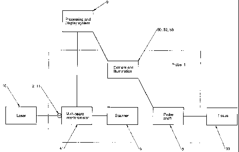
Figure 1 shows a block diagram of the OCT apparatus indicating a laser 10,
provided usually remotely from the probe 1, but in some circumstances within
the
probe 1. A laser beam 11 from the laser 10 is passed to the probe, usually
through a
single-mode optical fibre 2. The laser 10 provides a swept spectrum over a
wavelength range of at least 50 nm, within a region of the infra-red where
tissue
absorption is minimised. A wider spectrum improves the depth resolution. The
probe
1 comprises a multi-beam interferometer 41, a scanner 5, a probe shaft 6 and
camera
with illumination system 50, 52, 53, and other components detailed below. The
processing and display system 9 and tissue under examination 33 are external
to the
probe 1.
Figure 2 shows more detail of the probe 1. The probe 1 comprises a handle 3
containing an multi beam interferometer 41 and scanner 5, and a probe shaft 6.
The
probe 1 is constructed so that the shaft 6 can be detached from the handle 3.
The shaft
6 is constrained to a specific orientation, so that an output lens which
outputs a
multiple beam set and which is tilted by a small angle to eliminate
reflections, aligns
correctly with the scan direction. Other components described below have been
omitted from this diagram for clarity.
For the particular application of imaging the uterine cervix, suitable probe
shaft dimensions are 16 mm diameter at the proximal end 7 tapering to 12mm
diameter at the distal end 8 if required, and in the region of 220 mm length.
The
length of the scan line is made as large as possible, within the constraint of
the shaft
diameter, and in the described arrangement is 6.4 mm. The cone angle within
the
tissue is approximately f/ 8, which gives a depth of focus of about 0.3 mm.
One beam
of multiple beams used is essentially in focus from 0 to 0.3 mm depth, the
next beam
CA 02588697 2007-05-14
WO 2006/054116 PCT/GB2005/050196
from 0.3 mm to 0.6 mm and so on through to 1.2mm: the worst-case beam diameter
at
the tissue under examination (i.e. the width of a spot produced by the beam)
is about
10 m FWHM.
5 The distal end 8 of the probe shaft is convex to apply even pressure over
the
whole front face to the soft tissue under examination, irrespective of small
angular
departures from the normal onto the surface. Some other internal components
including rattle plate 13, lens 25, fold mirror 26, scan mirror 27 and
spectral
beamsplitter 28 are shown to facilitate orientation.
Optical description
Referring to Figure 3, the laser provides an output beam 11, via single mode
fibre 2, which is passed to a converging lens 12. After passing through the
converging
lens, the beam enters the rattle-plate beamsplitter 13. It may be desirable to
interpose
additional optical components in beam 11 (between the output from the fibre -
which
may already be collimated - and the rattle-plate) so that the beam diameter
can be
adjusted, and hence the desired convergence can be produced at the measurement
point. The rattle plate 13 splits the beam 11 into a number of weaker beams
that are
transmitted onwards; the detailed operation of the rattle plate is explained
with
reference to Figure 4.
Figure 4 is an optical diagram showing the operation of a partially and fully
reflecting pair of surfaces in forming a plurality of parallel beams. This
arrangement
is known as the rattle plate 13. The apparatus comprises a parallel-sided
glass plate
42, which on the entry face 44 has a high efficiency reflective coating to
provide a
reflective surface over area 43, leaving a non-reflective area 45 which may be
either
uncoated, or anti-reflection (AR) coated for better performance. The
transition
between these two areas is sharp. The exit face 46 is coated over the entire
surface
with a partially reflecting coating to provide a partially reflecting surface
47 such that
typically 8% to 25% of the incident light is transmitted, and the remainder
reflected.
CA 02588697 2007-05-14
WO 2006/054116 PCT/GB2005/050196
11
The incoming laser beam 11 passes through the non-reflective area 45 of face
44 (close to the boundary between the reflecting surface 43 and the non-
reflective
surface 45). Consequently, only a small amount of energy is lost on entry to
plate 42
(i.e. the Fresnel reflection if there is no AR coating in this part of the
plate, or less if
AR coated).
The laser beam 11 propagates through the plate 42, and in this example 13% is
transmitted at the partially reflecting surface 47 to provide the first beam
14, and the
remainder is reflected back towards the reflecting surface 43.
The plate 42 is tilted from orthogonal to the input beam 11 such that the beam
reflected from the partially reflecting surface 47 is directed towards the
high-
efficiency reflecting surface 43. Consequently the beam is then reflected back
(approaching 100% of the energy is reflected) to the partially reflecting
surface 47,
where a further 13% of the remaining beam power is transmitted to provide the
second beam 15. In this way, a series of beams of declining power are emitted
from
the plate, parallel to each other.
If the input beam 11 at the rattle plate is arranged to be convergent rather
than
collimated (for example by taking a collimated laser beam and passing it
through
converging lens 12), then the beams 14, 15 etc leaving the glass plate 42 will
focus at
different axial positions relative to each other, since each successive beam
follows a
longer path through the plate 42. The distance between the focal positions
will depend
upon the thickness, tilt angle and refractive index of the plate 42.
Alternatively, the
rattle plate assembly may comprise a fully reflecting and partially reflecting
surface
separated by air, as opposed to glass. Also, the input beam 11 may be
divergent rather
than convergent with suitable changes to the optical components.
The strongest five beams, 14 to 18, are allowed to propagate onwards, the
remainder are blocked by an opaque plate 19.
CA 02588697 2007-05-14
WO 2006/054116 PCT/GB2005/050196
12
Returning to Figure 3, the beams 14 to 18 from the rattle plate 13 are passed
to
a beam-splitter 20 which divides the beams into measurement beams 14M to 18M
and
reference beams 14R to 18R. The reference beam 18R is manipulated in the same
way
as the reference beams 14R to 17R, but it is not used to interfere with a
measurement
beam, rather it provides compensation for laser amplitude variation.
The reference beams 14R to 18R are reflected by the beam-splitter 20, pass
through lenses 21 and 22, reflect at a multifaceted mirror structure 23 then
re-pass
through lenses 22 and 21, and re-pass through beamsplitter 20. The
multifaceted
mirror structure 23 has a reflecting surface for each of the reference beams,
the
individual reflecting surfaces are set at the foci of the respective beams. It
may be
advantageous to set the angles of the reflecting surfaces one to the next to
ensure that
the reference beams 14R to 18R are accurately retro-reflected. Alternatively,
the
power and position of lenses 21 and 22 may be selected such that the axes of
reference beams 14R to 18R are parallel to each other. Note that the reference
optical
path is shown in the diagram as substantially shorter than measurement optical
path.
In practice, these paths would be very similar in length, because in a
frequency
domain OCT system the fringe frequency due to a target reflection is
proportional to
the path difference. Even if the electronic system could operate with
unlimited
bandwidth, there would be a constraint on maintaining similar path lengths,
since the
difference of the path lengths must be less than the coherence length of the
laser 10
for interference to occur. Another criterion for good interference between
measurement and reference beams is that the convergence and focal positions of
the
reference beams should match those of the measurement beams at the detectors.
To
achieve this, it is preferable to introduce additional reflecting or
refracting optical
components (such as an Offner relay) in the reference path to relay the focal
points at
or near beamsplitter 20 to the multifaceted reflecting surface 23.
The measurement beams 14M to 17M leave beamsplitter 20, and the weakest
beam 18M is blocked by an opaque plate 24. They are nominally collimated by
lens
CA 02588697 2007-05-14
WO 2006/054116 PCT/GB2005/050196
13
25, but there will be a slight difference between the convergence of the four
beams
since the path length between lenses 12 and 25 is different for each beam. The
separation between the two lenses is set so that the average optical path
length would
result in a collimated beam. The axes of the four beams 14M to 17M now
converge
towards each other. The beams are reflected at 90 orthogonal to the plane of
the
diagram at mirror 26, and propagate onwards, with the axes meeting at a scan
mirror
27.
The scan mirror 27 is driven to rotate nominally about an axis parallel to the
original axis of the beam 11, parallel to the plane of the diagram, scanning
the
measurement beams l4M to 17M. A further beamsplitter 28 is provided to reflect
measurement beams 14M to 17M along a new axis nominally parallel to the
original
beam axis of beam 11. The beamsplitter plate has a coating to selectively
reflect IR
radiation such as would be used for beams 14M to 17M, and to transmit visible
white
light.
A probe shaft 6 is provided. It comprises a metal tube mounting various
passive optical components (relay optical components) as will be described
hereafter.
The first (entry) lens group 30 in the probe shaft 6 forms a focus at 31 of
each
of the scanning measurement beams 14M to 17M within the probe shaft; other
lenses
relay the foci to a focus point just beyond the last lens 32 in the probe
shaft, that is,
just outside the distal end of the probe shaft. Because the measurement beams
l4M to
17M enter the probe shaft with a slightly different divergence from each
other, their
final focus 14F to 17F outside the probe shaft 6 for the respective beams 14M
to 17M
as shown in Figure 5, will be displaced axially relative to each other,
allowing optimal
signals to be derived from a different tissue depth (the tissue is indicated
at 33).
It will be seen that the last lens 32 forms the distal end of the probe shaft.
In
use, the distal end of the probe shaft formed by the lens 32 will be brought
into
CA 02588697 2007-05-14
WO 2006/054116 PCT/GB2005/050196
14
contact with the medical surface tissue 33 to be examined, optionally through
a thin
transparent disposable sheath.
As is shown in Figure 5, the foci 14F to 17F of the four measurement beams
14M to 17M will fall inside the tissue to be examined. This allows provision
of four
laser beams which are focussed at different depths, and though each beam
rapidly
comes out of focus as the depth varies, it is possible to cover all of the
depths of tissue
of interest within the focal range of one of the four beams. The axial spacing
of the
four foci is calculated to take into account the Rayleigh range of the focal
waist in the
tissue to be examined
Furthermore, because the four beams 14M to 17M strike the scan mirror 27 at
slightly different angles, the four foci 14F to 17F outside the probe shaft
are also
separated along the scan line by a distance indicated at A in Figure 5. The
distance A
is small (of the order of 0.2mm) and so the time between each of the beams
scanning
across a particular point in the tissue under examination is small (a few
percent of the
total scan time) and so the tissue under examination should not change between
the
passage of each beam.
Clearly as indicated above, one may have more or less than four beams which
have foci at a range of depths within the tissue. It will be noted that the
foci of the
four beams are displaced both laterally and axially from one to the next.
After scattering from the target tissue, components 14MR to 17MR of the four
beams are confocally collected back through the probe shaft. These return
beams
14MR to 17MR are de-scanned by the scan mirror 27 and pass back through lens
25.
A part of the each of the beams 14MR to 17MR is reflected by the beam-
splitter 20 and combined with the corresponding reference beam 14R to 17R. The
combined beams 14MR114R to 17MR/17R pass through a lens 34 which forms focal
points of each of the combined beams at detector 35. It will be seen that the
detector
CA 02588697 2007-05-14
WO 2006/054116 PCT/GB2005/050196
plane is tilted to the orthogonal angle of the incident combined beams axes
from the
normal to accommodate the focal shift originating from the rattle plate 13.
Interference between corresponding beams occurs at the surface of the detector
35.
The detector 35 will consist of a number of discrete sensitive areas, one for
each of
5 the combined beams, and an additional area for the reference beam 18R, which
is
used as a balance signal.
The beam-splitter 20, reference mirror structure 23, and individual detector
sensitive areas 36 to 39, and optical components form a Michelson
interferometer 41.
10 The interferometer arrangement allows the use of OCT and in particular the
optical
components are provided in this preferred embodiment to use frequency domain
OCT.
It will be seen that if beamsplitter 20 is a polarising beamsplitter, and
quarter
wave-plates are interspersed in both measurement and reference paths such that
the
15 measurement beams 14M to 17M, and reference beams 14R to 18R pass and re-
pass
through the wave-plates, and if an additional analysing component is added to
the
combined path so that a common polarising component of each of the beams is
selected, then the assembly will have a modified sensitivity to any polarised
properties of the tissue under examination.
Additional details are shown in Figure 6 and 7 to provide a viewing channel.
In Figure 6, the path of the OCT laser beams 14M to 17M is shown. The laser
beams 14M to 17M are traced from lens 25 (not shown), via mirror 26 onto the
scan
mirror 27, and through to the tissue at the distal end of the probe shaft 6. A
camera
chip 48, lens system 49 and illumination beamsplitter plate 50 are also shown.
Figure 7 shows the same components as Figure 6 but the illumination beams
51 and white light source 52 are shown, and the OCT laser beams are omitted
for
clarity. Figure 8 shows an additional view of the illumination beamsplitter
plate 50,
which is a reflecting surface with a central aperture. Light from white light
source 52
CA 02588697 2007-05-14
WO 2006/054116 PCT/GB2005/050196
16
is largely reflected by the illumination beamsplitter plate 50, although those
parts of
the beam which pass through the central aperture 54 are lost.
The apparatus of Figures 6 and 7 includes a spectral beam-splitter 28 which
separates OCT laser light from white light. The illumination beam-splitter
plate 50
and illumination source 52 are positioned to direct visible light which is
preferably
white light from the illumination light source 52 through the beamsplitter
plate 28,
and to pass a beam 51 of white light from the source 52 along the optical axis
within
the probe shaft 6. A white light LED is a suitable illumination source 52 but
others are
envisaged. Since the tissue surface 33 will be optically scattering, a
component part of
the returned reflected white light beam 51 will pass through the spectral beam-
splitter
28. A smaller component of this returned beam will pass through the aperture
54 in
the illumination beamsplitter plate 50 to a camera 53 which includes a CCD
detector
48. This is illustrated in Figure 9.
As is clear from Figures 6 and 7, the spectral beam-splitter 28 allows an
illuminating beam 51 to be passed to the surface under examination, the
illuminating
beam being mixed into the viewing channel by beam-splitter 50.
For preference, the entrance pupil 54 of the camera will be at a conjugate
point
to the reflective surface of the scan mirror 27, and also coincident with
aperture of the
illumination beamsplitter plate 50.
The camera 53 includes one or more lenses 49 to form an image of a surface to
be examined. The camera may be used to examine the surface 33 when it is in
contact
with the distal end of the probe shaft. Further, if the depth of focus of the
camera is
sufficient, it may be used when the distal end is spaced from the surface
allowing the
user to carry out a survey of the surface before selecting a particular part
to be
examined by OCT.
CA 02588697 2007-05-14
WO 2006/054116 PCT/GB2005/050196
17
Referring to fig 9, the image is focussed on either the image sensor surface
48
of the camera 53, or in an alternative arrangement, an end surface of a
coherent fibre
bundle 55 which leads to a remote CCD.
It will be noted that both the viewing optics and the OCT apparatus use the
same distal end lens 32 and so the part of the tissue viewed by the camera 53
and the
OCT interferometer 41 will be the same. Means may be provided for indicating
on the
displayed image the position of the OCT B-scan line.
Figure 10 shows a magnified view of the reference mirror structure 23.
Figure 11 shows the combined beams 14MR/14R to17MR/17R, and balance beam
18R forming individual foci on the detector surface 35. Figure 12 shows the
arrangement of the sensitive areas on the detector plane, one for each
combined beam,
and one for the balance beam 18R.
The embodiment so far described uses a single balance beam, and a
compensation signal derived from this beam is applied to each of the (four)
interference signals electronically. An alternative embodiment is to provide a
separate
balance beam matched optically to each reference beam; the paired beams are
then
detected using a balanced detector configuration.
Processing description
The laser provides a trigger signal to the processing system at the start of
each
frequency sweep. The processing system digitizes the analogue detector signals
and
stores the data (typically 1024 points) for the sweep, which provides the
information
to reconstruct one A-scan. The processing system may capture raw data for many
A-
scans (covering the entire movement of the scan mirror) before processing into
a
B-scan image, or alternatively capture and processing of A-scans may be
overlapped
in time.
An ideal laser source for frequency domain OCT would sweep at a constant
rate of optical frequency with time, and provide a constant level of power
during the
CA 02588697 2007-05-14
WO 2006/054116 PCT/GB2005/050196
18
sweep. In this case it would only be necessary to perform a discrete Fourier
transform
of the raw data (with an appropriate window function, eg Hanning) to obtain
the
A-scan profile.
For practical laser sources, the sweep rate varies across the spectrum, and so
does the power. If uncorrected these effects would result in blurred images.
Accordingly the raw data is corrected by resampling at unequal intervals using
a local
cubic interpolation algorithm, and by rescaling by varying factors. The
discrete
Fourier transform is then performed as above.
The calibration for the above corrections is obtained by using a plain glass
block as a target, to generate a single reflection of about 4% of incident
power (the
scan mirror is stationary, set to the central position, during calibration).
The path
difference is adjusted to give a suitably large number of fringes (for
instance 100
across the scan), and the raw waveform is captured. After removing any
residual dc
component, the computer accurately determines the position of the fringe zero
crossings using a local cubic interpolation algorithm, and hence obtains the
required
array of resampling positions. It also determines the envelope of the fringes,
and
hence obtains the required array of rescaling values. When the system is
correctly
calibrated, the glass block gives a sharp single peak in the A-scan.
Figure 13 shows a perspective view of the apparatus comprising a housing 100
mounting a computer system to analyse the interferograms and display the
results on a
screen 101. The housing 100 also mounts the laser, the output beam of which is
passed to the probe 1 via the flexible single-mode optical fibre 2.
The invention is not restricted to the details of the described examples.