Note: Descriptions are shown in the official language in which they were submitted.
CA 02588807 2007-05-18
WO 2006/060851
PCT/AU2005/001825
1
Magnesium alloys for hydrogen storage
Field of the invention
This invention relates to hydrogen storage materials and particularly relates
to a cast
alloy which can be used as a hydrogen storage material.
Background of the invention
As the world's population expands and economic activity increases, there are
ever
increasing signs that increasing atmospheric concentrations of carbon dioxide
are
warming the earth causing climate change. While the eventual depletion of the
world's
oil and fossil fuel energy sources will inevitably require other economic
energy sources
to be found, the more noticeable signs of global warming have increased
pressures for
global energy systems to move away from carbon rich fuels whose combustion
produces carbon monoxide and carbon dioxide gases.
Hydrogen energy is attracting a great deal of interest and is expected to
eventually be a
replacement for petroleum based fuels. However, there are still several
technical issues
and barriers that must be overcome before hydrogen can be adopted as a
practical fuel,
the main obstacle being the development of a viable hydrogen storage system.
While
hydrogen can be stored as a compressed gas or a liquid, the former occupies a
large
volume and the latter is energy intensive to produce, reducing any
environmental
benefits. In addition, both gaseous and liquid hydrogen are potentially
dangerous should
the pressure storage vessels be ruptured.
A safer, more compact method of hydrogen storage is to store it within solid
materials.
When infiltrated with hydrogen at relatively low pressures, metals and inter-
metallic
compounds can absorb large quantities of hydrogen in a safe, solid form. The
stored
hydrogen can be released when 'required by simply heating the alloy. Storage
of
hydrogen as a solid hydride can provide a greater weight percentage storage
than
compressed gas. However a desirable hydrogen storage material must have a high
CA 02588807 2007-05-18
WO 2006/060851
PCT/AU2005/001825
2
storage capacity relative to the weight of the material, a suitable desorption
temperature, good kinetics, good reversibility and be of a relatively low
cost.
Pure magnesium has sufficient theoretical hydrogen carrying capacity at 7.6 wt
%.
However the resulting hydride is too stable and the temperature must be
increased to
278 C for the hydrogen to be released. This desorption temperature makes such
materials economically unattractive. A lower desorption temperature is
desirable to not
only reduce the amount of energy required to release the hydrogen but to
enable the
efficient utilisation of exhaust heat from vehicles to release the hydrogen.
Compared to
pure magnesium, the compound Mg2Ni has a reduced hydrogen storage capacity of
3.6
wt % but, importantly, the temperature required for hydrogen release is
decreased to
less than that of pure magnesium. The mechanism of hydrogen storage is
believed to
involve the formation of (solid) hydride particles, i.e. MgH2 and Mg2N1H4 in
the
microstructure.
Recently, thixotropic casting techniques followed by partial remelting and
quenching
have been used [Y.-J. Kim, T.-W. Hong: Materials Transactions 43 (2002) 1741-
1747]
to produce hypoeutectic Mg-Ni alloys consisting of magnesium rich dendrides
surrounded by refined Mg-Mg2Ni eutectic. These alloys absorb large amounts of
hydrogen, similar to pure magnesium and display only a single hydrogen
absorption
plateau in the pressure-composition-temperature (PCT) curve, i.e. not separate
plateaus for each phase. It is believed that the nickel and/or Mg2N1 phase
acts as a
catalyst, improving the kinetics of hydrogen transfer into the magnesium rich
solid
phases via MgH2 formation.
This realisation has encouraged research [See review by S. Orimo and H. Fuji,
Applied
Physics A 72 (2001) 167-186] using nano technology and powder metallurgy
techniques
to produce materials with large internal interfacial areas. These techniques
are
attractive because they result in large interface areas and they introduce
crystallographic defects such as dislocations and twins, which could
distribute potential
catalysts throughout the microstructure, enabling them to have a widespread
influence
on the kinetics of the reaction. Unfortunately nano-scale powder metallurgy
techniques
offer limited control over the crystallographic structure of the phases (ie.
interfaces,
`004g82687
CA 02588807 2007-05-19
PCT/AU2005/001825
,
Received 06 October 2006
3
twins etc), the powder would be highly explosive and would be prohibitively
expensive
for large-scale mass production of commercial hydrogen storage components.
None of
the research reported to date considers methods by which higher performance
hydrogen storage components can be produced using lower cost processes more
applicable to mass production.
It is an object of the present invention to provide a castable MgNi alloy with
improved
hydrogen storage capabilities.
Reference to any prior art in the specification is not, and should not be
taken as, an
acknowledgment or any form of suggestion that this prior art forms part of the
common
general knowledge in Australia or any other jurisdiction.
Summary of the invention
According to one aspect, the invention may provide a method of producing a
hydrogen
storage material including the steps of forming a magnesium-nickel melt having
additions of at least one refining element, the refining element being able to
promote a
refined eutectic structure with increased twinning in the magnesium-nickel
intermetallic
phase and solidifying the magnesium-nickel melt to a hydrogen storage material
with
said refined eutectic structure.
In one preferred embodiment, the magnesium-nickel melt is formed by the steps
of
adding nickel to the magnesium melt to produce a hypoeutectic magnesium-nickel
alloy
(ie. greater than zero ¨ 23.5 wt% Ni), homogenising the magnesium-nickel melt,
and
adding the refining element or elements to the melt under a protective
atmosphere at
addition rates of greater than zero and up to 2 wt% and preferably greater
than zero and
less than 500 ppm.
The refining element has an atomic radius within the range of about 1-1.65
times that of
magnesium. It is understood that refining elements with atomic radii within
this range
will provide the refined eutectic structure discussed above. The refining
elements are
selected from the group comprising Zr, Na, K, Ba, Ca, Sr, La, Y, Yb, Rb, Cs
and rare
Amended Sheet
IPEA/AII
004882687
PCT/AU2005/001825
CA 02588807 2007-05-19
"
Received 06 October 2006
4
earth elements such as Eu. Zirconium is added to grain refine the magnesium
crystals
and when used requires at least one more of the elements from the group.
In another aspect, the invention may provide a method of producing a hydrogen
storage
material comprising the steps of forming a hypoeutectic magnesium nickel melt
having
additions of at least one refining element having an atomic radius within the
range of 1-
1.65 times that of magnesium, the refining element being provided in the melt
at
addition rates greater than zero and up to 2 wt % and preferably less than
2400 and
more preferably less than 500 ppm, and casting the magnesium nickel melt.
The solidifying step in both aspects is a casting step where the metal is cast
by a
suitable procedure such as pouring into preheated metallic moulds cooling the
casting.
The solidifying step may be other controlled solidifying processes. However,
once the
alloy has been cast it is then subject to activation and use as a hydrogen
storage
material. The alloy is preferably used in the cast condition.
In another embodiment of the invention, there is provided a hydrogen storage
alloy
comprising or consisting essentially of a hypoeutectic magnesium nickel alloy
having
greater than zero and up to 2 wt % of a refining element, the refining element
having an
atomic radius of about 1-1.65 times that of magnesium; and the balance
magnesium
and incidental impurities.
The refining additions are selected from the group of Zr, Na, K, Ba, Ca, Sr,
La, Y, Yb,
Rb, Cs and rare earth elements with addition rates greater than zero and up to
2 wt%
and preferably greater than zero and less than 2400 or more preferably greater
than
zero and less than 500 ppm. The more preferred addition elements are sodium
and
zirconium.
The applicants have found that by the addition of trace elements having atomic
radii of
about that of magnesium up to 1.65 times the atomic radius of magnesium to
hypoeutectic MgNi systems, twin crystal defects are encouraged in the Mg2Ni
intermetallic phase. It is thought that increasing the refinement and crystal
defects in the
Mg2Ni phase catalyses the hydriding reaction in the magnesium rich solid
Amended Sheet
IPEA/AU
CA 02588807 2007-05-18
WO 2006/060851
PCT/AU2005/001825
phases of the alloy, thus increasing the capacity of the alloy for hydrogen
uptake and
the kinetics of the hydrogen absorption.
Furthermore as the material is produced by a casting solidification process,
it is a more
commercially viable process for large scale mass production of hydrogen
storage
5 components.
Description of the drawings and preferred embodiment
Further features objects and advantages of the present invention will become
apparent
from the following description of the preferred embodiment and accompanying
drawings
in which
Fig 1 is a pressure composition temperature graph of an unmodified magnesium
alloy
with 14% Ni,
Fig 2 is a graph summarising activation time at 350 C and 2 MPa for Examples 1-
6,
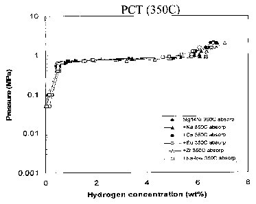
Fig 3 is a graph of PCT absorption data at 350 C and 2 MPa for Examples 1-6,
Fig 4 is a graph of PCT absorption data at 300 C and 2 MPa for Examples 1-6,
Fig 5 is a graph of PCT absorption data at 250 C and 2 MPa for Examples 1-6,
Fig 6 is a graph summarising PCT absorption capacity at 350 C and 2 MPa,
Fig 7 is a graph illustrating the relationship between absorption and
desorption for
unmodified Mg 14 Ni alloy,
Fig 8 is a graph of the desorption data at 0.2 MPa for Examples 1-6, and
Fig 9(a)-9(h) are SEM micrographs of the as cast alloys of Examples 1-6.
-004882687
CA 02588807 2007-05-19
PCT/AU2005/001825
Received 06 October 2006
,
6
The hydrogen storage material is produced according to the invention by
forming a
hypoeutectic magnesium-nickel by adding nickel to molten magnesium. The nickel
addition may be up to 20 wt% and preferably 10-20 wt % nickel. The melt is
then mixed
to provide a homogenised mix.
To this magnesium-nickel alloy, trace elements of crystallography modifying
material
are added. The elements added are those that refine the magnesium phase and
promote a refined eutectic structure with increased twinning in the magnesium-
nickel
intermetallic phase.
The range of elements satisfying the above two criteria have atomic radii
around that of
magnesium and up to 1.65 times that of magnesium and include Zr, K, Na, Ba,
Ca, Sr,
La, Y, Yb, Rb, Cs and rare earth metal elements. The preferred elements used
are
sodium and/or zirconium.
The melt is again stirred to homogenise the mix and held under a protective
atmosphere
during the homogenising step. The protective atmosphere is any atmosphere
which
prevents the magnesium from combusting. Typical atmospheres include SF6 and
HFC-
134a.
The metal is then cast by a suitable casting procedure such as by pouring into
preheated metallic moulds.
While not wishing to be restricted to a particular theory of operation, it is
considered that
the increase crystal defects, interfacial areas and density of dislocations
catalyses the
hydriding reaction in the magnesium rich solid phases of the alloy, thus
increasing the
capacity and kinetics of the alloy for hydrogen uptake.
Examples
The hydrogen absorption of metal hydride alloys is characterised using
equilibrium
pressure composition temperature (PCT) data. This data is obtained by keeping
an alloy
sample at constant temperature while precisely measuring the quantity of
hydrogen
Amended Sheet
WEAJAU
CA 02588807 2007-05-18
WO 2006/060851
PCT/AU2005/001825
7
sorbed and the pressure at which sorption occurs. The quantity of hydrogen
sorbed is
expressed in terms of alloy composition, either as an atomic ratio of hydrogen
atoms to
the number of atoms in the base metal alloy or as the capacity of hydrogen in
the
material on a weight percent basis.
PCT stands for "pressure-composition-isotherm" and shows the maximum hydrogen
absorption capacity possible at a fixed temperature. The pressure At
absorption is
higher than that at desorption and the region of the "plateau" indicates the
range
suitable for practical storage/release applications.
Most of the hydrogen is absorbed in a range where there is little pressure
change. This
region of near constant pressure is known as the plateau pressure. Metal
hydride
formation is also accompanied by hysteresis, which appears as the difference
between
the upper absorption curve and the lower desorption curve.
Example 1
An unmodified magnesium alloy containing 14 wt% Ni was subjected to a 2 MPa
hydrogen atmosphere at 350 C for a period of 20 hours. The pressure
composition
temperature data was recorded and shown in Figure 1.
From Figure 1, the activation time (At) of the alloy can be determined. The
"Activation
time" indicates how quickly an alloy becomes "ready" for use as a hydrogen
absorption
alloy. Shorter activation times save energy and are indicative of fundamental
material
differences in the kinetic performance of the alloys. Note that activation is
generally
required only once in the life-cycle of a hydrogen storage alloy. Once the
alloy has been
activated, the hydrogen absorption time is significantly reduced as evidenced
by the last
cycles of the run.
Examples 2-6
The magnesium nickel alloy of Example 1 was modified by the addition of a
refining
element.
1304882687
CA 02588807 2007-05-19
PCT/AU2005/001825
= =
Received 06 October 2006
8
Table 1 shows the refining element and the addition rate of that element.
Table 1
Example Refining element Addition rate
2 Na 2400 ppm
3 Na 600 ppm
4 Ca 800 ppm
Eu 600 ppm
6 Zr 2 wt%
The activation time from these examples is summarised in Figure 2. From these
results,
5 it can be seen that activation time can be reduced to about 40% of that of
the
unmodified alloy (from 8hours to 3.8hours). Hence for alloys at least up to
the addition
rates the activation time can be significantly reduced. This is of practical
significance but
more importantly it is indicative of the superior kinetic performance of the
modified alloy.
When the data collected in the above examples was analysed by reference to the
absorption curve only, the graph shown in Figure 3 was produced.
PCT curves (absorption only) at 350 C show all six samples can absorb around 7
wt%
hydrogen. There is little difference between the samples. 100% pure Mg absorbs
7.6
wt% of hydrogen and 7 wt% of hydrogen absorption is close to the theoretical
limits for
a Mg-14 wt% Ni sample. The Mg primary phases are regarded as the hydrogen
absorbing phases and eutectic regions are considered to have a catalytic
function
improving hydrogen kinetics.
The alloys of Examples 1-6, were then characterised at 300 C and 250 C with
the
absorption results shown in Figures 4 and 5 respectively.
Amended Sheet
IPEA/AII
004882687
CA 02588807 2007-05-19
PCT/AU2005/001825 I
,
Received 06 October 2006
9
At lower temperatures, there is a decreased capacity for absorption but a
large
difference in performance between alloys. The PCT curve (absorption only) at
300 C
clearly shows the improvement of hydrogen absorption from 5.7 wt% (unmodified)
to 6.6
wt% (Na high, Ca and Zr addition) or 6.8 wt% (Na low).
Figure 6 is a summary of the maximum hydrogen absorption capacity taken from
the
results shown in Figure 5. It can be seen that at 350 C the maximum hydrogen
storage
capacity is similar (around 7 wt%) for all samples cast.
At 250 C the modified alloys are superior and the maximum hydrogen capacity
can be
increased more than 1 wt% relative to the unmodified alloy (from 5.3 wt% to
6.5 wt%).
Even at 200 C (up to 2MPa condition), the samples are shown to absorb
approximately
5.5 wt% of hydrogen.
In regard to the desorption temperature, usually, at a fixed pressure,
absorption
temperature is lower than desorption temperature. The exact temperatures will
vary
depending on the pressure. Figure 7 shows the relationship between adsorption
and
desorption for the unmodified Mg 14Ni alloy at 0.2 MPa. The adsorption start
temperature 1 is usually higher than the adsorption end temperature 2. When
the alloy
then goes through the desorption cycle, the desorption start temperature 3 can
be seen
to be higher than the desorption end temperature 4.
In the representation of the modified alloys of Examples 2-6 relative to the
unmodified
alloys, it can be seen that the desorption end temperature (plateau region of
Figure 8) at
0.2 MPa decreases approximately 20 C with modification. In fact, the
desorption
temperature for the Mg Ni alloy can be reduced by trace element additions.
The addition of the modifying elements increases the amount of internal
interfacial
areas within the material, the amount of stacking faults and the density of
dislocations/twins in the solidified magnesium-nickel alloy. It is believed
that the refining
element should have an atomic radii in the range mentioned above in order to
achieve
the metallurgical effects in the as cast metal.
Amended Sheet
IPEA/AU
004882687
CA 02588807 2007-05-19
PCT/AU2005/001825
Received 06 October 2006
,
The increase in dislocations caused by the additions is illustrated in the SEM
micrographs Figures 9(a)-9(h). Figure 9(a) is the SEM for Mg 14 Ni unmodified;
Fig 9(b)
is the SEM for the same alloy with Zr addition; Figure 9(c) is the SEM for low
sodium
addition; Fig 9(d) is the SEM for high sodium addition; Figure 9(e) is the SEM
for
5 calcium addition; and Fig 9(f) is the SEM for Eu addition. Fig 9(g) is the
Mg 14 Ni
unmodified alloy of higher magnification; Fig 9(h) is the low sodium addition
at the
higher magnification of Fig 9(g).
Figure 9 shows SEM secondary electron images of hypo-eutectic Mg-14wt%Ni
alloys of
(a) and (g) unmodified, (b) 2wt%Zr addition, (c) and (h) 600ppm Na addition,
(d).
10 2400ppnn Na addition, (e) 800ppm Ca addition and (f) 600ppm Eu addition
alloys. The
black in the figures are primary Mg dendrites and small black and white
contrast is the
Mg-Mg2Ni eutectic structure. The images clearly demonstrate a very refined
fibrous eutectic microstructure in all modified samples compared with a coarse
eutectic
microstructure in the unmodified sample.
All modified samples show a relative improvement of approximately 1 wt% for
the
maximum hydrogen absorption capacity. The refinement of the structure, even at
trace
levels of addition is considered quite remarkable yielding eutectic spacings
below 1 m
and often below 500 nnn. Thus, a nano-scale material is obtained through the
combination of an alloy modification and a casting method.
Amended Sheet
IPEA/AU