Note: Descriptions are shown in the official language in which they were submitted.
CA 02589000 2009-04-06
1
A STENT
This application is a divisional of co-pending Canadian Patent Application
No. 2,235,783, filed April 24, 1998.
Background of the Invention
This invention relates to a stent. Stents are used in lumens in a human or
animal body. When properly positioned in a lumen, a stent can contact the wall
of
the lumen to support it or to force the wall outwardly.
Stents can be made from a material which enables the stent to be
compressed transversely elastically so that they can then recover outwardly
when
the compressing force is removed, into contact with the wall of the lumen. The
enhanced elastic properties available from shape memory alloys as a result of
a
transformation between martensite and austenite phases of the alloys make them
particularly well suited to this application. The nature of the superelastic
transformations of shape memory alloys is discussed in "Engineering Aspects of
Shape Memory Alloys", T. W. Duerig et al, on page 370, Butterworth-Heinemann
(1990).
A principal transformation of shape memory alloys involves an initial
increase in strain, approximately linearly with stress. This behavior is
reversible,
and corresponds to conventional elastic deformation. Subsequent increases in
strain are accompanied by little or no increase in stress, over a limited
range of
strain to the end of the "loading plateau". The loading plateau stress is
defined by
the inflection point on the stress/strain graph. Subsequent increases in
strain are
accompanied by increases in stress. On unloading, there is a decline in stress
with
reducing strain to the start of the "unloading plateau" evidenced by the
existence of
an inflection point along which stress changes little with reducing strain. At
the
end of the unloading plateau, stress reduces with reducing strain. The
unloading
plateau stress is also defined by the inflection point on the stress/strain
graph. Any
residual strain after unloading to zero stress is the permanent set of the
sample.
Characteristics of this deformation, the loading plateau, the unloading
plateau, the
CA 02589000 2006-12-22
2
elastic modulus, the plateau length and the permanent set (defined with
respect to a
specific total deformation) are established, and are defined in, for example,
"Engineering Aspects of Shape Memory Alloys," on page 376.
Summary of the Invention
The stress strain behaviour of a shape memory alloy component which
exhibits enhanced elastic properties can exhibit hysteresis, where the stress
that is
applied at a given strain during loading is greater than the stress exerted at
that
strain during unloading. It is generally desirable when exploiting the
enhanced
elastic properties of a shape memory alloy component to minimise the
difference
between the stresses on the loading and unloading curves in a deformation
cycle
(that is to minimise the hysteresis). However, according to the present
invention, it
has been found that it can be advantageous in a stent to make use of an alloy
which
is capable of exhibiting a large hysteresis in a loading and unloading cycle.
This
can be obtained by using certain nickel titanium based alloys, with ternary
additions of at least one of niobium, hafnium, tantalum, tungsten and gold.
The invention provides a stent for use in a lumen in a human or animal
body, which has a generally tubular body formed from a superelastic shape
memory alloy having an Af temperature less than about 15 C and which has been
treated so that it exhibits enhanced elastic properties with a point of
inflection in
the stress-strain curve on loading, enabling the body to be deformed inwardly
to a
transversely compressed configuration for insertion into the lumen and then
revert
towards its initial configuration, into contact with and to support the lumen,
the
difference between the stress on loading and the stress on unloading at the
respective inflection points on the stress-strain curve, after deformation to
a strain
of 10%, being at least about 250 MPa.
The use of the specific ternary elements in a nickel titanium alloy has the
advantage that the resulting stent is able to exhibit a wider hysteresis in
the stress-
strain behaviour in a loading and unloading cycle. This is particularly
advantageous in a stent for use in a lumen in a human or animal body, which is
moved through the stent while in a transversely compressed configuration from
which it can expand elastically into contact with and to support the lumen.
The
wide hysteresis means that the inward force required to compress the stent
CA 02589000 2006-12-22
3
transversely once in place in the lumen is relatively high, while the outward
force
that the stent exerts on the lumen as it attempts to revert to its original
undeformed
configuration is relatively low. This can also mean that the lumen will be
resistant
to being crushed by externally applied forces which can be a problem in the
case of
lumens close to the surface such as arteries in the thigh and neck. It can
also mean
that the lumen does not tend to be distorted undesirably by a large outward
force
exerted by the stent on the lumen.
The use of the alloy specified above can enable the ratio of the stress on
loading to the stress on unloading at the respective inflection points on the
stress-
strain curve to be at least about 2.5:1, preferably at least about 3:1, more
preferably
at least about 3.5:1, for example at least about 4:1, measured at body
temperature.
This relationship between the loading and unloading stresses in the loading-
unloading cycle provides the combination of resistance to crushing of a stent-
supported lumen and low outward force tending to deform the lumen, discussed
above.
The present invention further provides a stent for use in a lumen in a human
or animal body, which has a generally tubular body formed from a shape memory
alloy which has been treated so that it exhibits enhanced elastic properties
with a
point of inflection in the stress-strain curve on unloading, enabling the body
to be
deformed inwardly to a transversely compressed configuration for insertion
into
the lumen and then revert towards its initial configuration, into contact with
and to
support the lumen, the ratio of the stress on loading to the stress on
unloading at
the respective inflection points on the stress-strain curve being at least
about 2.5:1,
preferably at least about 3:1, measured at body temperature.
The use of the alloy specified above can enable the difference between the
stress on loading and the stress on unloading at the respective inflection
points on
the stress-strain curve, after deformation to a strain of 10%, to be at least
about 250
MPa, preferably at least about 300 MPa, more preferably at least about 350
MPa,
for example at least about 400 MPa. This relationship between the loading and
unloading stresses in the loading-unloading cycle can also provide the
combination
of resistance to crushing of a stent-supported lumen and low outward force
tending
to deform the lumen, discussed above.
CA 02589000 2006-12-22
4
Accordingly, in compliance with the present invention, the invention
provides a stent for use in a lumen in a human or animal body, which has a
generally tubular body formed from a shape memory alloy having an Af
temperature less than about 15 C, which has been treated so that it exhibits
enhanced elastic properties with a point of inflection in the stress-strain
curve on
loading, enabling the body to be deformed inwardly to a transversely
compressed
configuration for insertion into the lumen and then revert towards its initial
config.iration, into contact with and to support the lumen, the difference
between
the stress on loading and the stress on unloading at the respective inflection
points
on the stress-strain curve, after deformation to a strain of 10%, being at
least about
250 MPa, preferably at least about 300 MPa, more preferably at least about 350
MPa, for example at least about 400 MPa.
A further significant advantage of the use of at least some of the alloys
referred to above in the stent of the invention is that their radio-opacity is
enhanced
compared with that of nickel-titanium shape memory alloys conventionally used
for stents, greatly facilitating their use in non-invasive surgery.
The alloy used in the stent of the invention will preferably comprise at least
about 3 at. % , more preferably at least about 5 at. % of one or more
additional
elements. The alloy will preferably comprise not more than about 15 at. % ,
nlore
preferably not more than about 10 at. % of the additional element(s). The
alloy
will often contain just nickel and titanium in addition to elements selected
from the
group referred to above (as well of course of incidental amounts of other
materials
including impurities), although useful alloys may include two or more elements
(of
which at least one, and possibly all, may be selected from the group referred
to
above) in addition to nickel and titanium. An example of a suitable alloy for
use in
the stent of the invention is Ni44Ti47Nbg. The relative amounts of the nickel
and
titanium components in the alloy will be selected to provide appropriate
elastic
properties and to ensure that the temperatures of the transitions between the
martensite and austenite phases of the alloy can be arranged to be appropriate
for
the intended use of the stent.
Some NiTiNb alloys which can be used in the present invention are
disclosed in U.S. Pat. No. 4,770,725. That document relates to NiTiNb alloys
which have been found to be capable of treatment to provide a wide thermal
CA 02589000 2009-04-06
hysteresis. This property is important in applications for shape memory alloys
which make use of a thermally induced change in configuration. Such a change
can
result by first deforming an article made from the alloy is from a heat-stable
configuration to a heat-unstable configuration while the alloy is in its
martensite
phase. Subsequent exposure to increased temperature results in a change in
configuration from the heat-unstable configuration towards the original heat-
stable
configuration as the alloy reverts from its martensite phase to its austenite
phase.
The wide thermal hysteresis that is available by thermal and mechanical
treatment of the alloys disclosed in U.S. Pat. No. 4,770,725 is attractive for
articles
which make use of a thermally induced configuration change since it enables an
article to be stored in the deformed configuration in the martensite phase at
the
same temperature at which it will then be in use, in the austenite phase.
While the
wide hysteresis that is referred to in U.S. Pat. No. 4,770,725 confers certain
advantages when the thermally induced changes in configuration are to be
exploited, a wide hysteresis in stress-strain behaviour on loading and
unloading is
generally inconsistent with the properties of an alloy that are looked for
when its
enhanced elastic properties are to be exploited.
The alloy used in the stent will be treated so as to provide appropriate
elastic properties for the intended application. The treatment will generally
involve a combination of thermal and mechanical treatment steps. Non-linear
superelastic properties can be introduced in a shape memory alloy by a process
which involves cold working the alloy for example by a process that involves
pressing, swaging or drawing. The cold working step is followed by an
annealing
step while the component is restrained in the configuration, resulting from
the cold
working step at a temperature that is sufficiently high to cause dislocations
introduced by the cold working to combine and dislocations to align. This can
ensure that the deformation introduced by the cold work is retained.
The technique for introducing superelastic properties can be varied from that
described above. For example, instead of subjecting the alloy to a heat
treatment
while restrained in the deformed configuration, the alloy could be deformed
beyond a particular desired configuration and then heat treated such that
CA 02589000 2006-12-22
6
there is a thermally induced change in configuration of the kind discussed
below,
the change taking the configuration towards the particular desired
configuration.
Introduction of the superelastic properties might also involve annealing at
high
temperature (for example towards the recrystallisation temperature of the
alloy),
followed by rapid cooling and then a heat treatment at a lower temperature.
An example of a treatment that can be applied to a Ni44Ti47Nbg alloy to
provide suitable enhanced elastic properties includes cold working the article
by at
least about 20%, preferably at least about 30%. The cold work will generally
be
less than about 60%, preferably less than about 50%. Cold work of about 40%
can
be appropriate for many articles. The treatment generally includes an
annealing
step involving exposure to elevated temperature for a period of at least about
1
minute, preferably at least about 10 minutes, generally less than about 500
minutes,
preferably less than about 60 minutes. The annealing temperature will
preferably
be at least about 300 C, more preferably at least about 550 C, preferably less
than
about 550 C, more preferably less than about 450 C.
Preferably, the Aftemperature (the temperature at which the transformation
from martensite phase to the austenite phase is complete) of the alloy is at
least
about 10 C, more preferably at least about 15 C, especially at least about 20
C.
Preferably, the Af temperature of the alloy is not more than about 50 C, more
preferably not more than about 40 C, especially not more than about 35 C. The
At,
temperature of the alloy will generally be arranged to be no more than about
the
body temperature that will be encountered by the stent when it is in use. A
stent
inade from an alloy whose transformation temperatures fall within one or more
of
these ranges has been found to exhibit appropriate elastic properties.
The stent of the invention will generally have an apertured or open
configuration which facilitates the controlled transverse compression and then
outward recovery in use into contact with the wall of a lumen. The apertured
configuration can comprise slits, or bigger openings. A stent with an
apertured
configuration can be formed by cutting a tube. It might also be formed fi=onl
wire
using an appropriate bonding technique (such as welding) at points where wires
cross.
The configuration of the apertures in the stent will be selected to provide
appropriate deformation characteristics, on both transverse compression prior
to
CA 02589000 2006-12-22
7
use and subsequently when the stent is disposed in a lumen. The configuration
should also provide appropriate flexibility for the stent, prior to and during
use. It
is particularly desired that (a) the flexibility of the stent when bent
relative to its
longitudinal axis should be high, (b) the stent should be able to recover
elastically
from transverse compression, for example changing its configuration from
elliptical to say circular, and (c) the radial stiffness of the stent should
be high.
The stent can be made by a process which involves removing material from
a sheath-like object, leaving a pattern of material with appropriate hoop
portions
and struts. The nature of the removal process will depend on the material of
the
sheath-like object. For example, the removal process may involve one or more
of
cutting, melting and vaporising the material. When the stent is formed from a
metal material, the removal process can involve use of a laser cutting tool.
Other
techniques which might be used for forming the pattern in the material include
stamping, cutting, and etching (especially photoetching).
The sheath-like object from which the stent is formed can be a tubular
object, especially a cylindrical tube with a circular cross-section. However,
the
sheath can be filled with a core material. The core can support the sheath
during
the removal process. This can prevent or at least restrict deformation of the
sheath
during the removal process, and damage to the opposite side of the sheath from
the
point at which it is being cut by an external cutting tool. The core can be
provided
as a rod which can be slid into the sheath. The core and the sheath might be
formed as a single article, for example by a cold drawing technique.
While the removal process referred to above is preferred for forming the
stent of the invention, it might be formed in other ways, for example from
wire by
welding. The stent could also be made from sheet material which can be formed
into a tube, for example by folding and welding.
Preferably, the wall thickness of the material of the stent less than about
1.5
mm, more preferably less than about 0.8 mm. Preferably, the wall thickness is
at
least about 0.1 mm, more preferably at least about 0.2 mm.
Preferably, the maximum transverse dimension (which will be its diameter
when the stent has a circular cross-section) of the stent (which will be its
diameter
when the stent has a circular cross-section) is not more than about 40 mm,
nlore
preferably not more than about 20 mm, especially not more than about 10 mm.
CA 02589000 2006-12-22
8
Preferably, its minimum transverse dimension is at least about 0.5 mm, more
preferably at least about 1 mm.
The stent of the invention will be located in a lumen while in a deformed
configuration in which it has been compressed transversely elastically. It
will be
held in this configuration by means of a restraint. The restraint can
conveniently
be a catheter. The stent can be discharged from the catheter in the desired
location
in a lumen by means of an appropriate pusher such as a wire inserted into and
pushed along the catheter.
Summary to the Drawings
Figure 1 is a transverse view of a stent in the configuration prior to
deformation for location in a catheter in which it can be delivered to a
desired
position in a lumen.
Figure 2 is a transverse view of the stent shown in Figure 1, after transverse
deformation to a configuration in which it can be delivered to a desired
position in
a lumen.
Figure 3 demonstrates the stress-strain behaviour of the stent shown in
Figures 1 and 2 during a loading and unloading cycle.
Description of Preferred Embodiments
Figure 1 shows a stent formed from an alloy which consists essentially of
44 at. % Ni, 47 at. % Ti and 9 at. % Nb. It is formed from a tube of the alloy
by
selective removal of the material of the alloy, for example by means of a YAG
laser cutter, leaving an open array of wire-like elements 2 which define an
array of
diamond shaped openings 4 arranged along the longitudinal axis 6 of the tube.
The
openings are such that the transverse dimension of the tube (which will be its
diameter if it has a circular cross-section) can be increased or decreased by
changing the shape of the openings. The shape is changed by changing the
angles
between the wire-like elements, effectively by flattening or opening the
diamond
shapes of the openings.
The cut tube is treated to give the alloy enhanced elastic properties by a
process involving the steps described above, including for example cold work
by
about 35% and annealing at about 400 C for about 10 minutes. As a result, the
CA 02589000 2006-12-22
9
stent might be capable of being deformed elastically to a strain of up to
about
8.5%, and its Af temperature is about 30 C.
Figure 2 shows the stent shown in Figure 1 after compression so that its
diameter is reduced. The reduction in diameter is accompanied by a change in
the
shape of the diamond shape openings 4 so that they are flattened
circumferentially
and elongated in a direction parallel to the axis 6 of the stent. The
compression is
elastic. The stent is deployed in a lumen in a human or animal body while
restrained in the compressed configuration, for example by means of a catheter
in
which the stent is disposed for delivery. It can be compressed by means of a
tapered catheter leading into the delivery catheter (in the manner of a
funnel).
Once appropriately located in the delivery catheter, the stent can be
delivered to
the desired location in the lumen. It can be discharged from the delivery
catheter
by means of a pusher wire, using generally known techniques.
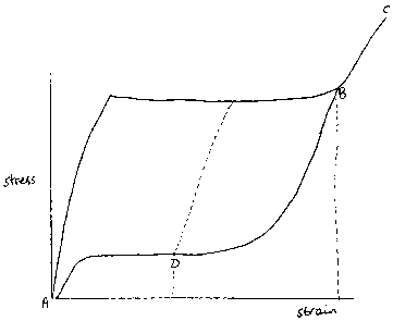
Figure 3 illustrates the deformation behaviour of the stent of the invention.
It shows how stress varies with strain during deformation of a catheter. The
behaviour is shown at a fixed temperature which, when approximately equal to
the
body temperature to which the stent is exposed in use, demonstrates how a
stent
will perform once located in a lumen. Normally, the initial deformation of the
stent from the configuration shown in Figure 1 towards that in Figure 2 will
be
carried out at ambient temperature which might result in a loading curve that
might
differ slightly from that shown in Figure 3.
The configuration of the stent as cut (as shown in Figure 1) is represented
by point A, where there is no strain. Compression of the stent (to the
configuration
shown in Figure 2) is represented by the upper curve to point B, with a strain
of
about 6% and a stress of about 800 MPa. The limit of the elastic recoverable
deformation of the stent is at point C: up to point C, the stent can recover
at least
about 90% of the initially applied strain and that strain can then be
recovered
repeatedly. The deformation of the stent to the configuration represented by
point
B can involve for example insertion into a small bore catheter, for example
fi=om a
diameter of 8 mm to a diameter of 3 mm. Release of the stent without any
constraint allows the stent to expand towards its initial configuration at
point A
along the lower curve. However, in use, the recovery of the stent is
restrained by
the lumen into which the stent is discharged so that the stent will adopt a
CA 02589000 2006-12-22
configuration represented by a point D on the lower curve, between the points
B
and A.
From point D, the force that is exerted outwardly on the lumen as it
attempts to recover further towards point A is represented by the stress on
the Y-
axis corresponding to point D: the stress remains substantially constant at a
relatively low level as the strain is reduced. However, on compression of the
stent
(such as under an externally applied force in the case of a lumen close to the
surface), the stent follows the dotted loading curve towards the upper loading
curve, ultimately towards the point B. As the strain increases, the stress
increases
quickly, providing resistance to the compressive force as required to provide
continued support to the lumen in which the stent is disposed.
The hysteresis loop that is apparent in the stress-strain behaviour shown in
Figure 3 has a large difference in stress between the upper loading and lower
unloading curves. This difference enables the stress on continued relaxation
of
strain to remain low and relatively constant, and the resistance to
compressive
forces to be maintained low, as discussed above. The difference between the
stresses on the loading and unloading curves at the respective points of
inflection is
about 400 MPa. The ratio between the said stresses is about 3:1.