Note: Descriptions are shown in the official language in which they were submitted.
CA 02589113 2007-05-09
WO 2006/056807 PCT/GB2005/004777
1
Title - improvements reiating to Respiratory Circuits
This invention relates to respiratory circuits, and in particular to
respiratory
circuits including cartridges of material for treating respiratory gases.
In anaesthetic respiratory circuits, chemical absorbents are generally used to
remove carbon dioxide from exhaled respiratory gases. In such respiratory
circuits, the chemical absorbent is usually contained within a cartridge
incorporated into the respiratory circuit. In particular, such cartridges
include
an inlet at one end of the cartridge and an outlet at the other end of the
cartridge such that exhaled respiratory gases flow through the interior of the
cartridge and are treated by the chemical absorbent contained therewithin.
A variety of different forms of such chemical absorbents are well known in the
art, but the chemical absorbent is usually granular in form. The inlet and
outlet
conventionally take the form of circular meshes located at opposite ends of a
generally cyiindricai cartridge. The chemical absorbent normally includes a pH
indicator, such as ethyl violet, that changes colour, eg from coiouriess to
violet
in the case of ethyl violet, when the chemical absorbent is exhausted and
hence no longer able to effectively absorb carbon dioxide. At least a side
wall
of the cartridge is therefore usually sufficiently translucent for such a
colour
change to be visible to a user. Most chemical absorbents also produce heat
and water on reaction with the respiratory gases, and so act to humidify and
heat the respiratory gases flowing through the cartridge.
The circular mesh that forms the inlet is generally of lesser diameter than
the
diameter of the cartridge. For this reason, conventional cartridges generally
suffer from the major disadvantage that respiratory gases tend to flow
predominantly through a central cylindrical channel of the interior of the
cartridge and hence a central cylindricai core of the chemical absorbent.
As a consequence, a centrai cylindrical core of the chemical absorbent
typically becomes exhausted before the surrounding chemical absorbent, and
CA 02589113 2007-05-09
WO 2006/056807 PCT/GB2005/004777
2
hence there is non-uniform use of the chemical absorbent within the cartridge.
The cartridge will therefore become ineffective and will need to be replaced
before an outer portion of the chemical absorbent has been fully exhausted.
This is clearly a waste of chemical absorbent. In addition, any colour change
of the chemical absorbent in the central core will not be visible through the
side
wall of the container, and hence a user is given no indication of the
inactivity of
the cartridge until a carbon dioxide waming indicator, which is conventionally
included in a respiratory circuit, is activated.
There has now been devised an improved cartridge for incorporation within a
respiratory circuit which overcomes or substantially mitigates the above-
mentioned and/or other disadvantages associated with the prior art.
According to a first aspect of the invention, there is provided a cartridge
for
incorporation within a respiratory circuit, the cartridge being adapted to
contain
a material for treating respiratory gases and comprising an inlet and an
outlet
such that respiratory gases flow, in use, through the interior of the
cartridge
and interact with said material, wherein the cartridge includes means for
guiding the respiratory gas transversely relative to its direction of flow
through
the interior of the cartridge.
The cartridge according to the invention is advantageous principally because
the respiratory gas can be guided transversely so as to flow substantially
uniformly through the interior of the cartridge. The present invention
therefore
significantly reduces the amount of material for treating the respiratory
gases
that is wasted by ensuring that the materiai is uniformly active throughout
the
interior of the cartridge during use. This increases the lifetime of a given
size
of cartridge, and hence reduces cost.
The cartridge according to the invention is suitable for incorporation within
a
respiratory circuit, such as an anaesthetic respiratory circuit. Typically,
the
material for treating respiratory gases will be a chemical absorbent for
CA 02589113 2007-05-09
WO 2006/056807 PCT/GB2005/004777
3
absorbing, and hence removing, carbon dioxide from the respiratory gases
flowing through the interior of the cartridge.
The cartridge may be charged with material for treating respiratory gases by
the end user, or more preferably the cartridge is supplied as a disposable
unit
that is already charged with such material. In either case, the end user
preferably incorporates the charged cartridge into a respiratory circuit using
attachment means that are well known in the art. The respiratory circuit will
typically supply exhaled respiratory gases to the inlet of the cartridge, and
remove treated respiratory gases from the outlet of the cartridge.
The inlet and outlet are preferably provided at opposite ends of the
cartridge,
and typically the inlet is provided in the base of the cartridge. Materiai for
treating respiratory gases, such as chemical absorbents for absorbing carbon
.15 dioxide, are generally granular in form. The inlet and/or outlet therefore
preferably comprise a plurai'rty of openings formed in a wall of the
cartridge, the
openings being sufficiently small to retain the granular material within the
cartridge. Most preferably, the inlet and outlet each have the form of a mesh.
In preferred embodiments, the cartridge comprises a generally cylindrical
container with a base and an open upper end, and a lid that is releasably
engaged with the open upper end of the container.
The inlet is preferably annular in form, and most preferably comprises a
plurality of openings in the form of an annular mesh. The annular nature of
the
inlet reduces the proportion of the respiratory gas that flows directly into a
central region of the cartridge.
The means for guiding the respiratory gas transversely relative to the
direction
of flow through the interior of the cartridge is preferably situated within
the
cartridge, and is most preferably situated immediately adjacent to the inlet.
The respiratory gases are preferably guided transversely relative to the
direction of flow through the interior of the cartridge before there is any
CA 02589113 2007-05-09
WO 2006/056807 PCT/GB2005/004777
4
interaction between the respiratory gases and the material within the
cartridge.
In particular, the cartridge preferably defines one or more paths of least
resistance for the respiratory gases that each extend from an opening of the
inlet, and each extend transversely relative to the surface of the material
within
the cartridge that is adjacent to the inlet, such that respiratory gases flow
along
a path of least resistance before flowing through the material within the
cartridge.
The means for guiding the respiratory gas transversely relative to the
direction
of flow through the interior of the cartridge, and hence In certain
embodiments
transversely relative to the surface of the material within the cartridge that
is
adjacent to the inlet(s), preferably takes the form of one or more formations
on
an interior surface of the cartridge. Such formations may have any form
suitable for guiding the respiratory gas transversely relative to the
direction of
flow through the interior of the cartridge. For instance, the formations may
include one or more baffles that deflect the respiratory gases transversely
relative to the direction of flow through the interior of the cartridge. The
one or
more baffles may be defined by an interior surface of the container.
In presently preferred embodiments, the cartridge comprises a plurality of
formations that define a plurality of channels on the interior surface of the
cartridge along which respiratory gases flow before interacting with the
material within the cartridge. Most preferably, each opening of the inlet is
In
communication with a channel on the interior surface of the cartridge, and the
channels are preferably arranged across the entire end of the cartridge in
which the inlet is formed.
Most preferably, each channel includes an open face, and the material within
the cartridge contacts the formations so as to cover those open faces but not
to pass between the formations into the channels. The path of least resistance
for respiratory gases flowing through the openings of the inlet will therefore
be
along the channels rather than through the material within the cartridge.
However, once the channels are charged along their full extent, the
respiratory
CA 02589113 2007-05-09
WO 2006/056807 PCT/GB2005/004777
gases will flow through the material. Hence, the respiratory gas will flow
substantially uniformly throughout the interior of the cartridge. Where the
inlet
is formed in the base of the cartridge, the material within the cartridge will
be
supported by the upper surface of the formations defining the channels.
5
In preferred embodiments, the formations have the form of ribs that are each
orientated parallel to an adjacent rib so as to define a channel therebetween.
Such ribs may be generally linear in form, and may be arranged in sets of
similarly orientated ribs. In any case, the ribs are preferably arranged such
that the channels defined by the ribs cause the respiratory gases to flow
uniformly over the end of the cartridge in which the inlet is formed before
interacting with the material within the cartridge.
According to a further aspect of the invention, there is provided a
respiratory
circuit incorporating a cartridge as hereinbefore described. Typically, the
respiratory circuit will be a respiratory anaesthesia circuit.
The invention will now be described In greater detail, by way of illustration
only,
with reference to the accompanying drawings, in which
Figure 1 is a side view of a prior art cartridge comprising a container and
lid;
Figure 2 is a plan view of the lid of the prior art cartridge;
Figure 3 is a view of the container of the prior art cartridge from above,
with the
lid of the cartridge removed;
Figure 4 is a perspective view, from above, of the container of the prior art
cartridge;
Figure 5 is a plan view of a container forming part of a cartridge according
to
the invention;
CA 02589113 2007-05-09
WO 2006/056807 PCT/GB2005/004777
6
Figure 6 is an underside view of the container of the cartridge according to
the
invention;
Figure 7 is a perspective view, from above, of the container of the cartridge
according to the invention; and
Figure 8 is a perspective view of the container of the cartridge according to
the
invention in an inverted condition.
Figure 1 shows a prior art cartridge 10 that is adapted to contain a
material,for
treating respiratory gases. In use, the prior art cartridge 10 is incorporated
Into
a respiratory circuit such that respiratory gases flow through the interior of
the
cartridge 10 and are treated by the material contained therewithin.
Conventionally, the prior art cartridge 10 contains a chemical absorbent (not
shown in the Figures) for absorbing carbon dioxide from the respiratory gases
flowing through the interior of the cartridge 10. A variety of different forms
of
such chemical absorbents are well known in the art. However, the chemical
absorbent is usually granular in form with a minimum dimension In any axis of
about 3mm. or greater. In addition, the chemical absorbent normally includes a
pH indicator, such as ethyl violet, that changes colour, eg from colouriess to
violet in the case of ethyl violet, when the chemical absorbent is exhausted
and hence no longer able effectively to absorb carbon dioxide. Most chemical
absorbents also produce heat and water on reaction with the respiratory
gases, and so act to humidify and heat the respiratory gases flowing through
the cartridge 10.
The prior art cartridge 10 shown in Figure 1 comprises a container 20 and a
lid
which together house the chemical absorbent, in use, and allow the
30 throughflow of respiratory gases. The container 20 is cylindrical in form
with a
generally planar base and an open upper end (as viewed in Figure 1). The lid
30 is circular and includes a downwardly extending skirt at its periphery. The
downwardly extending skirt includes a lower portion that is received within
the
CA 02589113 2007-05-09
WO 2006/056807 PCT/GB2005/004777
7
upper end of the container 20 with a close, interference fit, and an upper
portion having a greater external diameter that abuts the upper edge of the
container 20. In this way, the lid 30 is releasably engaged with the container
20.
The container 20 and lid 30 are each formed in plastics material as a unitary
component. At least the side wall of the container 20, and conventionally the
entire prior art cartridge 10, is sufficiently translucent for any colour
change of
the chemical absorbent within the cartridge 10 to be readily visible.
As shown in Figure 2, the lid 30 includes a circular mesh 32 comprising a
regular array of square openings. The circular mesh 32 is situated at the
centre of the lid 30, and extends radially a distance of about ha{f of the
radius
of the lid 30. An annular portion of the lid 30, which is continuous in form,
surrounds the mesh 32. The openings of the mesh 32 allow respiratory gases
to flow out of the prior art cartridge 10 through that part of the lid 30.
Figures 3 and 4 show the container 20 of the prior art cartridge 10, and
illustrate that the base of the container 20 includes a circular mesh 22 that
is
identical in form to the circular mesh 32 of the lid 30. An annular portion of
the
base of the container 20, which is continuous in form, surrounds the mesh 22.
The openings of the mesh 22 allow respiratory gases to flow into the prior art
cartridge 10 through that part of the base of the container 20.
The external surface of the base of the container 20, and the extemal surface
of the lid 30, are both adapted to engage respiratory apparatus such that
exhaled respiratory gases are supplied to the prior art cartridge 10 through
the
mesh 22 of the container 20 and treated respiratory gases are discharged
through the mesh 32 of the lid 30. Such engagement means are well known in
the art, and typically take the form of formations that are integrally formed
with
the container 20 and lid 30.
CA 02589113 2007-05-09
WO 2006/056807 PCT/GB2005/004777
8
In use, the prior art cartridge 10 is charged with a suitable granular
chemical
absorbent, as discussed above. The chemical absorbent will have minimum
granular dimensions such that granules of the absorbent cannot pass through
the mesh 22,32 of the container 20 or lid 30. Conventionally, the prior art
cartridge 10 is orientated in an upright position during use, as shown in
Figure 1, and is charged with a chemical absorbent up to a level that is
approximately 5mm below the interior surface of the lid 30. The cartridge 10
is
incorporated into a respiratory circuit by means that are well known in the
art.
Respiratory gases flow through the prior art cartridge 10 and react with the
chemical absorbent such that carbon dioxide is removed from the respiratory
gases and absorbed by the chemical absorbent. When the chemical
absorbent is exhausted, and hence can no longer efficiently absorb carbon
dioxide, the pH indicator in the chemical absorbent will change colour, eg
from
colouriess to violet or from pink to white, so as to indicate to the user that
the
chemical absorbent Is exhausted.
The prior art cartridge 10 described above with reference to Figures 1 to 4
suffers from the major disadvantage that respiratory gases tend to flow
predominantly through a central cylindrical channel of the interior of the
cartridge 10 and hence a central cylindrical core of the chemical absorbent.
This means that a central cylindrical core of the chemical absorbent will
become exhausted before the surrounding chemical absorbent, and hence
there is non-uniform use of the chemical absorbent within the cartridge 10. As
a consequence, the cartridge 10 will be become ineffective, and will need to
be
replaced, before an outer portion of the chemical absorbent has been fully
exhausted. This is clearly a waste of the chemical absorbent. In addition, any
colour change of the chemical absorbent in the central core will not be
visible
through the side wall of the container, and hence a user is given no
indication
of the inactivity of the cartridge until a carbon dioxide warning indicator,
which
is conventionally included in a respiratory circuit, is activated.
CA 02589113 2007-05-09
WO 2006/056807 PCT/GB2005/004777
9
An. example of a cartridge according to the invention comprises a container
120 as shown in Figures 5 to 8 and a lid (not shown in Figures 5 to 8) that is
identical to the lid 30 of the prior art cartridge 10 described above. The
cartridge according to the invention differs from the prior art cartridge 10
only in
relation to the form of the container 120 of the cartridge, as described
below.
The container 120 shown in Figures 5 to 8 is cylindrical in form with a
generally
planar base and an open upper end that engages with the lid. The container
120 is injection moulded in plastics material as a unitary component.
The exterior surface of the base of the container 120, as shown in Figures 6
and 8, includes an annular mesh 122 of openings, the majority of which have
the general shape of a rectangle or parallelogram. The mesh 122 is
surrounded by a continuous annular portion of the base of the container 120,
and the mesh 122, in tum, surrounds a continuous circular disc at the centre
of
the base of the container 120. The openings of the mesh 122 enable
respiratory gases to flow into the cartridge through that part of the base of
the
container 120.
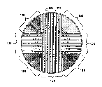
The interior surface of the base of the container 120, as shown in Figures 5
and 7, includes a plurality of ribs 124,126,128 that are arranged across the
entire interior surface of the base. The ribs 124,126,128 are each generally
linear in form and extend between the openings of the mesh 122. In this
arrangement, the ribs 124,126,128 cooperate to define a plurality of channels
through which respiratory gases flow, in use. In particular, each opening of
the
mesh 122 opens into one of the channels formed by the ribs 124,126,128.
The ribs 124,126,128 are arranged in a number of sets, with the ribs
124,126,128 of each set being oriented parallel to one another and each rib
124,126,128 being separated from an adjacent rib 124,126,128 so as to define
a channel therebetween.
CA 02589113 2007-05-09
WO 2006/056807 PCT/GB2005/004777
A first set of ribs 124 is provided that forms a band extending across a
diameter of the base. Two second sets of ribs 126 are provided that are each
orientated perpendicularly to the first set of ribs 124, and each forms a band
that extends between the edge of the first set of ribs 124 and the periphery
of
5 the base. Finally, four third sets of ribs 128, which are each oriented
generally
radially and at 45 to both the first and second sets of ribs 124,126, extend
over the remaining areas of the base. The inner end of each of the third ribs
128 is separated from the adjacent first or second rib 124,126 so that the
ends
of the channels defined by the third ribs 128 are connected and hence in
10 communication. In this way, each channel defined by the third ribs 128 is
in
communication with an opening of the mesh 122. In addition, the first and
second ribs 124,126 that are immediately adjacent to,the ends of the third
ribs
128 include discontinuities that allow the flow of respiratory gas
therethrough,
and hence further facilitate the flow of respiratory gas into the channels
defined
by the third ribs 128.
In use, the cartridge is charged with a suitable granular chemical absorbent
up
to a level that is approximately 5mm below the interior surface of the lid.
The
chemical absorbent will have minimum granular dimensions such that granules
of the absorbent cannot pass between adjacent ribs 124,126,128 into the
channels deflned by the ribs 124,126,128, and hence cannot pass through the
mesh 122 of the container 120. When the cartridge has been charged with the
chemical absorbent, a body of chemical absorbent will therefore rest upon, and
be supported by, the upper surfaces of the ribs 124,126,128 such that the
respiratory gases are free to flow unimpeded along the channels defined by
the ribs 124,126,128.
The cartridge may be charged by the end user, or more preferably the
cartridge is supplied as a disposable unit that is already charged. In either
case, the end user incorporates the charged cartridge into a respiratory
circuit
by means that are well known in the art.
CA 02589113 2007-05-09
WO 2006/056807 PCT/GB2005/004777
11
Exhaled respiratory gases are supplied to the openings of the mesh 122, and
flow therethrough. These respiratory gases will then follow a path of least
resistance, and hence flow along the channels that are defined by the ribs
124,126,128 and extend from the openings of the mesh 122. Respiratory
gases will then flow upwardly from all points of each channel into and through
the body of chemical absorbent. Since the channels defined by the ribs
124,126,128 offer a path of least resistance, the channels will remain charged
with respiratory gases and respiratory gases will continue to flow upwardly
from all points of each channel during use.
Respiratory gases flowing through the body of chemical absorbent will react
with the chemical absorbent such that carbon dioxide is removed from the
respiratory gases and absorbed by the chemical absorbent. The ribs
124,126,128 and channels defined therebetween ensure that respiratory gases
flow at the same rate through all parts of the body of chemical absorbent,
thereby ensuring uniform usage of the chemical absorbent throughout the
cartridge.
When the chemical absorbent is exhausted, and hence can no longer
efficiently absorb carbon dioxide, the pH indicator in the chemical absorbent
will change colour, eg from colourless to violet or from pink to white, so as
to
indicate to the user that the chemical absorbent is exhausted. Since
respiratory gases are flowing at the same rate through all parts of the body
of
chemical absorbent, the chemical absorbent adjacent to the transparent side
wall of the container 120 will change colour when the chemical absorbent
throughout the cartridge is exhausted and hence the cartridge needs to be
replaced.
The cartridge according to the present invention therefore significantly
reduces
the amount of chemical absorbent that is wasted by ensuring that the chemical
absorbent is uniformly active throughout the cartridge. This increases the
lifetime of a given size of cartridge, and hence reduces cost. In addition, as
soon as the cartridge has become ineffective due to exhaustion of the
CA 02589113 2007-05-09
WO 2006/056807 PCT/GB2005/004777
12
chemical absorbent, the colour change of the indicator within the chemical
absorbent will be readily visible through the translucent side wall of the
cartridge.
Finally, the extemal diameter of the mesh 122 of the container 120 is
substantially similar to the external diameter of the mesh 22 of the prior art
container 20. Hence, the cartridge of the invention is able to cooperate with
the attachment means of.existing anaesthetic machines and other respiratory
apparatus.