Note: Descriptions are shown in the official language in which they were submitted.
CA 02589306 2007-05-18
FURNITURE HINGE
The present invention claims the benefit of German Patent Application No.
2006 034 306.9, filed July 21, 2006.
5
BACKGROUND OF THE INVENTION
This invention relates to a furniture hinge. More particularly, this invention
relates to a furniture hinge having a door rabbet element that is rotatably
disposed on
a carrier arm that is longitudinally and laterally adjustably disposed on a
mounting
10 plate attachable to a furniture frame. A fastening plate, which is made in
one piece
with the carrier arm and which lies against the mounting plate, is carried
longitudinally on the mounting plate. The fastening plate exhibits, on the end
toward the carrier arm, a lateral adjusting screw in a threaded hole. The
screw
accommodates the two edges of a longitudinal slot in the mounting plate in a
circumferential groove.
Some furniture hinges serve for the pivotable attachment of a furniture door
to a piece of furniture. To align the furniture door with the furniture,
furniture hinges
may be laterally adjustable so that the furniture door can be adjusted in the
horizontal direction along a front surface of the furniture. Furniture hinges
may be
additionally longitudinally adjustable so that the separation between the
furniture
door and the front surface of the furniture body, for example, a front frame,
is
adjustable.
Known furniture hinges use a lateral adjustment screw to adjust the
separation between the fastening plate and the end of the mounting plate
toward the
carrier arm. A circumferential groove of the lateral adjustment screw
accommodates
two edges of a longitudinal slot in the mounting plate. The slot is open in
the
direction of the carrier arm to permit assembly by inserting the lateral
adjustment
screw. The lateral adjustment screw rotates within the longitudinal slot of
the
mounting plate without axial displacement. Since the lateral adjusting screw
is
accommodated in a threaded hole in the fastening plate, rotation of the screw
changes the distance between the fastening plate and the mounting plate.
1
CA 02589306 2007-05-18
At another end of the hinge away from the carrier arm, the fastening plate
and the mounting plate connect together in such a way that their separation
remains
unchanged. The two adjacent sections of the fastening plate and the mounting
plate
are in relatively close proximity. An eccentric element joins these two
plates.
Moving the eccentric element longitudinally adjusts the fastening plate
relative to
the mounting plate in a direction transverse to the front surface of the
furniture.
The eccentric element may rotatably attach to the mounting plate through a
pivot having an eccentric section extending through a cross-slot in the
fastening
plate. Rotating the eccentric element longitudinally displaces the fastening
plate
with respect to the mounting plate, which is fixedly attached to the body of
the
furniture. This displaces the lateral adjustment screw within the longitudinal
slot.
A cutout in the longitudinal slot, open in the direction of the carrier arm,
facilitates assembly of the fastening plate onto the mounting plate. However,
when
overloaded, the connection between the fastening plate and the mounting plate
in the
longitudinal direction of adjustment may fail. For example, if the mounting
pin of
the eccentric element is pulled out of the mounting plate, the fastening plate
can be
pulled away from the mounting plate in the longitudinal direction. Overloading
a
furniture door by a force operating from above, such as when a person pulls
down
on the furniture door, exerts a horizontal tension force on the upper
furniture hinge
of the furniture door. If the furniture hinge fails in the manner described
above, the
furniture door may break loose from the furniture frame in the region of the
upper
furniture hinge. In many cases loads on the upper furniture hinge extend to
the lower
furniture hinge. If both hinges fail under load, the furniture door falls from
the body
of furniture. This can lead not only to serious damage to the piece of
furniture, but
also to injuries.
It would be desirable to design a furniture hinge that lessens the risk of the
door rabbet element separating from the mounting plate under load.
SUMMARY
An example furniture door hinge includes a carrier arm having a first arm
end and a second arm end, a door rabbet element rotatably fastens to the first
arm
end, and a fastening plate is disposed on the second arm end. The fastening
plate is
2
CA 02589306 2007-05-18
formed with the carrier arm and has a threaded hole near the carrier arm for
receiving a lateral adjustment screw. A mounting plate attaches to the body of
a
piece of furniture, the second arm end longitudinally and laterally adjustably
connects to the mounting plate and the fastening plate longitudinally guided
across
the mounting plate. The lateral adjustment screw accommodates at least one
edge of
a longitudinal slot in the mounting plate within a circumferential groove. The
longitudinal slot is closed near the carrier arm and enlarged away from the
carrier
arm to receive the screw head.
Another example furniture door hinge includes a longitudinal slot in a
mounting plate having a closed end toward a carrier arm and an enlarged end
away
from the carrier arm. The enlarged end is adapted to accommodate the insertion
of
the bolt head.
BRIEF DESCRIPTION OF THE DRAWINGS
The various features and advantages of this disclosure will become apparent
to those skilled in the art from the following detailed description. The
drawings that
accompany the detailed description can be briefly described as follows.
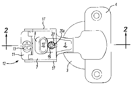
Figure 1 illustrates a top view of an example furniture hinge.
Figure 2 illustrates a side sectional view along line 2-2 of Figure 1
Figure 3 illustrates a bottom view of the example furniture hinge.
Figure 4 illustrates a front sectional view along line 4-4 of Figure 2.
Figure 5 illustrates a mounting plate of the example furniture hinge
DETAILED DESCRIPTION
Referring to Figures 1 and 2, the example furniture hinge pivotably attaches
a furniture door 1 to a furniture frame. For example, the example hinge
attaches to a
furniture front frame 2 of a piece of furniture of the "face-frame" design.
The furniture hinge includes an insert cup, a type of door rabbet element 3.
Screws (not shown) driven through screw-attachment tabs 4 attach the door
rabbet
element to the furniture door 1. A carrier arm 5 includes on one end toward
furniture
door 1 a rotatable hinge or linkage consisting of a hinge pin 6. The hinge pin
6
3
CA 02589306 2007-05-18
attaches the carrier arm 5 to the door rabbet element 3, which is secured to
the
furniture door 1. The carrier arm 5 is formed from sheet-metal for example.
A fastening plate 7 is disposed on another end of the carrier arm 5, the end
away from the furniture door 1. The carrier arm 5 and the fastening plate 7
are
formed in one piece, for example. The fastening plate 7 connects to a mounting
plate 8, which is screwed onto front-frame 2.
The mounting plate 8 attaches to the front-frame 2 using a fastening screw 9,
which is indicated by a broken line in Figure 2. The fastening screw 9 extends
through an elongated hole 10 that extends perpendicularly across the mounting
plate
8 to the longitudinal direction of the mounting plate 8. The elongated hole 10
permits height adjustment when fastening the mounting plate 8 to the front-
frame 2.
A cross-step 11 on the fastening plate 7 adjustably connects to the mounting
plate 8 with a longitudinal adjustment provision 12. The longitudinal
adjustment
provision 12 includes an eccentric element 14 having a Philips-head screw head
for
receiving an adjusting tool. The eccentric element 14 is rotatably
accommodated in
the mounting plate 8 by means of a pivot 15. An eccentric section 16 of the
eccentric
element 14 extends into a cross-slot 30 in the cross-step 11. Rotating the
eccentric
element 14, adjusts the fastening plate 7 longitudinally (i.e., horizontally
in Figs. 1
and 2) relative to the mounting plate 8, which is fixedly attached to the body
of the
furniture. The fastening plate 7 engages the longitudinal edges of the
mounting plate
8 at edge flanges 17 and is thus guided in the longitudinal direction.
Upsetting the pivot 15 rotatably fixes the pivot 15 in the hole in the
mounting
plate 8. The cross-step 11 of the fastening plate 7 is thereby fixed in
contact with the
mounting plate 8 at this end of the fastening plate 7.
At the end of the fastening plate 7 toward the carrier arm 5, the fastening
plate 7 accommodates a lateral adjustment screw 19 in a threaded hole 18
extending
perpendicular to the plane of the plate, as shown in Figures 3 and 4. The
screw 19
includes a screw head 20 having a slot 20a or a Philips-head accommodation.
The lateral adjustment screw 19 has a circumferential groove 21 on the end
opposite the screw head 20. The circumferential grove 21 separates a second
screw
head 22 from other portions of the screw 19.
4
CA 02589306 2007-05-18
The circumferential groove 21 behind the screw head 22 accommodates the
two edges 23 of the longitudinal slot 24 of the mounting plate 8. As shown in
Figure
5, the longitudinal slot 24 is closed at the end toward the carrier arm 5 by a
stop 25
and includes an enlargement 26 on the other end.
The width of the slot between the two edges 23 is sized such that the neck of
the screw head 22 formed by circumferential groove 21 fits between the
longitudinal
edges, while the screw head 22 extends past the two slot edges 23. During
longitudinal adjustment of the fastening plate 7, the lateral adjustment
screws 19
slides along the keyhole-shaped longitudinal slot 24.
The enlargement 26 at the end of the longitudinal slot 24 is sized to permit
insertion of the screw head 22 during assembly.
By rotating the lateral adjustment screw 19, the carrier-arm end of the
fastening plate 7 pivots relative to the mounting plate 8, while the other
end, the end
away from the carrier arm 5, maintains its position because the cross-step 11
is held
in position on the mounting plate 8 by the eccentric element 14.
This pivoting motion of the mounting plate 7 as a result of the rotation of
the
lateral adjustment screw 19 also causes pivoting of the carrier arm 5. Through
the
linkage formed by the hinge pin 6, the door rabbet element 3 moves the
furniture
door 1 sideways in the front plane of the piece of furniture.
The longitudinal adjustment provision 12 adjusts the fastening plate 7, the
carrier arm 5, and the door rabbet element 3 so that the distance between the
closed
furniture door 3 and the front-frame 2 can be adjusted.
When an overload breaks or loosens the connection between the fastening
plate 7 and the mounting plate 7, the lateral adjustment screw 19 slides in
the
longitudinal slot 24 toward the carrier arm 5 only as far as the narrow end of
the
longitudinal slot 24. The lateral adjustment screw 19 maintains this position
so that
the door rabbet element 3 disposed on the carrier arm 5 does not immediately
and
completely separate from the mounting plate 7 under load. Instead, the lateral
adjustment screw 19, which is screwed into the fastening plate 7, remains
within the
longitudinal slot 24 of the mounting plate 7. The lateral adjustment screw 19
only
separates when the loading becomes so great that the lateral adjustment screw
19,
5
CA 02589306 2007-05-18
the material surrounding the longitudinal slot 24, or both are deformed and
destroyed. Such a result assumes an increasing load.
The preceding description is exemplary rather than limiting in nature.
Variations and modifications to the disclosed examples may become apparent to
those skilled in the art that do not necessarily depart from the essence of
this
disclosure. The scope of legal protection given to this disclosure can only be
determined by studying the following claims.
6