Language selection

Search

Patent 2589417 Summary

Third-party information liability

Some of the information on this Web page has been provided by external sources. The Government of Canada is not responsible for the accuracy, reliability or currency of the information supplied by external sources. Users wishing to rely upon this information should consult directly with the source of the information. Content provided by external sources is not subject to official languages, privacy and accessibility requirements.

Claims and Abstract availability

Any discrepancies in the text and image of the Claims and Abstract are due to differing posting times. Text of the Claims and Abstract are posted:

  • At the time the application is open to public inspection;
  • At the time of issue of the patent (grant).
(12) Patent: (11) CA 2589417
(54) English Title: BAR CLAMP
(54) French Title: SERRE-JOINT A BARRE
Status: Expired and beyond the Period of Reversal
Bibliographic Data
(51) International Patent Classification (IPC):
  • B25B 05/16 (2006.01)
  • B25B 05/00 (2006.01)
  • B25B 05/02 (2006.01)
(72) Inventors :
  • SPRINGER, SCOTT D. (United States of America)
(73) Owners :
  • ADJUSTABLE CLAMP COMPANY
(71) Applicants :
  • ADJUSTABLE CLAMP COMPANY (United States of America)
(74) Agent: OSLER, HOSKIN & HARCOURT LLP
(74) Associate agent:
(45) Issued: 2010-02-02
(86) PCT Filing Date: 2006-11-08
(87) Open to Public Inspection: 2007-05-31
Examination requested: 2007-05-22
Availability of licence: N/A
Dedicated to the Public: N/A
(25) Language of filing: English

Patent Cooperation Treaty (PCT): Yes
(86) PCT Filing Number: PCT/US2006/043579
(87) International Publication Number: US2006043579
(85) National Entry: 2007-05-22

(30) Application Priority Data:
Application No. Country/Territory Date
11/287,025 (United States of America) 2005-11-23

Abstracts

English Abstract


A clamp is adapted to be secured to a second
substantially identical clamp in order to accommodate a
larger workpiece than can be held by a single clamp. The
clamp includes a first jaw that is secured to an
intermediate member, such as a bar or pipe, and a second jaw
that is removeably securable to the intermediate member so
as to selectively oppose the first jaw. The second jaw
includes a surface thereon that is configured to interlock
with a complimentarily-shaped surface on a second jaw of the
second clamp.


French Abstract

L'invention concerne un serre-joint (10) conçu pour être fixé sur un second serre-joint sensiblement identique (10A) de sorte à s'adapter à une pièce de grande dimension destinée à être maintenue par un serre-joint unique. Ce serre-joint comprend une première mâchoire (12) qui est fixée sur un élément intermédiaire (16), notamment une barre ou un conduit, et une seconde mâchoire qui peut être fixée amovible sur l'élément intermédiaire, de sorte à être en opposition sélective par rapport à la première mâchoire. La seconde mâchoire comprend une surface (34) conçue pour s'interverrouiller avec une surface de forme complémentaire située sur une seconde mâchoire du second serre-joint.

Claims

Note: Claims are shown in the official language in which they were submitted.

-8-
WHAT IS CLAIMED:
1. A clamp adapted to be secured to a second
substantially identical clamp comprising:
a first jaw secured to an intermediate member; and
a second jaw removably securable to the intermediate member
so as to selectively oppose the first jaw, and the second
jaw having a surface thereon configured to interlock with a
complementarily-shaped surface on a second jaw of the second
clamp.
2. The clamp of claim 1 wherein the surface of the
second jaw comprises a projection substantially on a first
side of a centerline of the second jaw and a
complementarily-shaped recess substantially on a second side
of the centerline, the projection and recess being
configured so that the surface on the second jaw may
interlock with an identically-configured second jaw of a
second clamp.
3. The clamp of claim 2 wherein the projection is
symmetrical in shape and comprises a narrow neck portion and
a relatively larger head portion, the recess is symmetrical
in shape with a narrow mouth and a relatively larger
interior, and the head portion of the projection being
larger than the mouth portion of the recess.

-9-
4. The clamp of claim 3 wherein the projection and
the recess are dovetail-shaped.
5. The clamp of claim 4 wherein the projection and
the recess are T-shaped.
6. The clamp of claim 3 wherein the head portion of
the projection and the interior of the recess are ball-
shaped.
7. The clamp of claim 1 wherein the first jaw is
slidably received on the intermediate member.
8. The clamp of claim 1 wherein the intermediate
member comprises a bar.
9. The clamp of claim 1 wherein the intermediate
member comprises a pipe.
10. A bar clamp comprising:
an elongated bar;
a movable jaw slidably received on the bar; and
a second jaw removably securable to the bar, and
having a surface thereon configured to interlock with a
complementarily-shaped surface on a second jaw of a second
bar clamp.
11. The bar clamp of claim 10 wherein the surface of
the second jaw comprises a projection substantially on a
first side of a centerline of the second jaw and a
complementarily-shaped recess substantially on a second side

-10-
of the centerline, the projection and recess being
configured so that the surface on the second jaw may
interlock with an identically-configured second jaw of a
second bar clamp.
12. The bar clamp of claim 11 wherein the projection
is symmetrical in shape and comprises a narrow neck portion
and a relatively larger head portion, the recess is
symmetrical in shape with a narrow mouth and a relatively
larger interior, the head portion of the projection being
larger than the mouth portion of the recess.
13. The bar clamp of claim 12 wherein the projection
and the recess are dovetail-shaped.
14. The bar clamp of claim 13 wherein the projection
and the recess are T-shaped.
15. The bar clamp of claim 12 wherein the head portion
of the projection and the interior of the recess are ball-
shaped.

Description

Note: Descriptions are shown in the official language in which they were submitted.


CA 02589417 2007-05-22
WO 2007/061636 PCT/US2006/043579
-1_
BAR CLAMP
BACKGROUND OF THE INVENTION
[0001] Bar clamps are among the most widely used fixtures
by craftsmen and woodworkers. Bar clamps typically include
a first "fixed jaw" secured, in place on a bar or pipe and a
second moveable jaw secured to the bar or pipe in opposition
to the first jaw. See, e.g. U.S. 1,783,713 (showing a bar
clamp) and U.S. 6,338,478 (showing pipe clamp).
[0002] Selecting the appropriate bar clamp for a
particular job depends upon the size of the work piece to be
held. Bar clamps are typically available in lengths ranging
from 6 inches to 8 feet, and it is not unusual for a
tradesman to have a large number of bar or pipe clamps in
varying lengths in order to be prepared for most
contingencies. Most hobbyists and do-it-yourselfers,
however, are unlikely to own bar clamps in the many varying
lengths available, and are thus more likely to encounter
situations where a clamp is needed with a larger space
between the fixed and moveable jaws than is at hand.
[0003] Accordingly, it is an object of the present
invention to provide a bar clamp which can be joined to a
similarly configured bar clamp to increase the working
distance between the jaw members on the clamp.

CA 02589417 2007-05-22
WO 2007/061636 PCT/US2006/043579
-2-
SUMMARY OF THE INVENTION
[0004] This object, and others which will become apparent
upon reference to the following detailed description and
accompanying drawings, is provided by a clamp that is
adapted to be secured to a second substantially identical
clamp. The clamp includes a first jaw that is secured to an
intermediate member, such as a bar or pipe, and a second jaw
that is removably securable to the intermediate member so as
to selectively oppose the first jaw. The second jaw
includes a surface thereon that is configured to interlock
with a complimentarily-shaped surface on a second jaw of the
second clamp.
[0005] Preferably, the surface of the second jaw
comprises a projection substantially on a first side of a
center line of the second jaw and a complimentarily-shaped
recess substantially on a second side of the center line.
The projection and the recess are configured so that the
surface on the second jaw interlocks with an identically-
configured second jaw of a second clamp. Preferably, the
projection is symmetrical in shape, and has a narrow neck
portion with a relatively larger head portion. The recess
is also symmetrical in shape with a narrow mouth and a
relatively larger interior. The head portion of the
projection is larger then the mouth portion of the recess.

CA 02589417 2007-05-22
WO 2007/061636 PCT/US2006/043579
-3-
The projection and recess may be in any of a number of
shapes, such as dove tail-shaped, T-shaped, and ball-shaped.
BRIEF DESCRIPTION OF THE DRAWINGS
[0006] Fig. 1 is a plan view of a bar clamp in accordance
with the present invention.
[0007] Fig. 2 is a plan view of a first bar clamp
according to the present invention connected to a second bar
clamp according to the present invention, thereby extending
the working length of the bar clamp.
[0008] Fig. 3 is a bottom view of the interconnected jaw
members of the two bar clamps shown in Fig. 2.
[0009] Fig. 4 is a top view of a fixed jaw in accordance
with the present invention.
[00010] Fig. 5 is a plan view of a fixed jaw in accordance
with the present invention.
[00011] Fig. 6 is a side view of a fixed jaw in accordance
with the present invention.
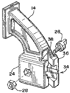
[00012] Fig. 7 is a perspective view of a fixed jaw in
accordance with the present invention.
DETAILED DESCRIPTION OF THE PREFERRED EMBODIMENT
[00013] Turning to Figs. 1 and 2, there is seen a bar
clamp, generally designated 10, that can be joined to a
second bar clamp, generally designated 10A, having a
configuration substantially identical to the bar clamp 10 to

CA 02589417 2007-05-22
WO 2007/061636 PCT/US2006/043579
-4-
permit the user to create a bar clamp adapted for use with
larger work pieces, as shown in Fig. 2.
[00014] The clamps 10, 10A each include a moveable jaw 12
and a fixed jaw 14, both of which are received on a slide
bar 16. The moveable jaw 12 is formed integrally with a
handle/grip assembly 18 that includes a first operating
handle 20 for incrementally advancing the moveable jaw 12
along the slide bar 16 toward the fixed jaw 14, and a second
operating handle 22 for releasing the slide bar 16 so that
the moveable jaw 12 can freely slide away from the fixed jaw
14, as is well known in the art. An internal mechanism for
the handle/grip assembly 18 may be as shown in U.S. patent
no. 6,655,670, which is incorporated here and by reference.
[00015] The fixed jaw 14 includes a sleeve portion 24 that
receives the slide bar 16 so that the fixed jaw 14 may be
removably secured to the slide bar 16 by means of a thumb
screw 26 and a nut 28. The shank of the screw 26 is
received in a hole 30 adjacent the end of the slide bar 18.
[00016] The clamp 10 as shown in Fig. 1, is configured for
holding a work piece between the two opposed jaw 12, 14.
The removeability of the fixed jaw 14 allows the clamp 10 to
be reconfigured for use as a spreader. To this end, the
fixed jaw 14 is removed from the first end of the slide bar
16, the handle/grip assembly 18 is moved toward the first

CA 02589417 2007-05-22
WO 2007/061636 PCT/US2006/043579
-5-
end of the slide bar 16, and the fixed jaw 14 is secured to
the second end of the slide bar so that its jaw faces away
from the jaw 12 on the handle/grip assembly 18. Thus, the
slide bar 16 includes a hole 30 adjacent each end to
facilitate selectively securing the fixed jaw 14 to either
end. In the preferred embodiment, each end of the slide bar
also includes a stop 32 that extends transversely beyond the
face of the slide bar 16 for keeping the handle/grip 18
assembly associated with the slide bar 16.
[00017] In keeping with the invention, the sleeve 24 of
the fixed jaw 14 is formed with a surface, generally
designated 34, that is configured to interlock with a
similar surface on the fixed jaw of a second bar clamp, thus
permitting the user to create an extended bar clamp as shown
in Fig. 2.
[00018] As best seen in Figs. 3, 4 and 7, the surface 34
comprises a projection 36 and a complementarily-shaped
recess 38. When viewed from above, as soon in Fig. 3,
projection 36 is symmetrical in shape and comprises a narrow
neck portion 40 and a relatively larger head portion 42.
The recess 38 is similarly symmetrical in shape and has a
narrow mouth portion 44 with a relatively larger interior
46. As can be appreciated, the head 42 of the projection 36
is larger than the mouth 44 of the recess 38 so that two

CA 02589417 2007-05-22
WO 2007/061636 PCT/US2006/043579
-6-
interlocked fixed jaws 14 will resist separation when a
clamping force is exerted in a direction of the longitudinal
axis of the slide bar 16, but can slide apart if a force is
exerted perpendicular to the axis of the slide bar. In the
illustrated fix jaws, the projections and recesses are
dovetail-shaped. However, they can also be T-shaped or
ball-shaped without departing from the invention.
[00019] Consequently, a pair of bar clamps 10, 10A of the
type described above can be joined together by first
removing the fixed jaws 14 from their respective slide bars
16. The fixed jaws 14 are then rotated 180 degrees about
the axes of their respective slide bars 16 and then
reattached thereto so that the jaw of the fixed jaw 14 is on
the opposite side of the slide bar 16 from the jaw on the
moveable jaw 12. -The interlocking surfaces 34 of the fixed
jaws 14 are joined together in a sliding motion, as
indicated by the arrows in Fig. 2, so that the fixed jaws 14
interlock and the moveable jaws 12 of. the bar clamps 10, l0A
are in opposition so that a work piece can be secured
therebetween.
[00020] Thus, a bar clamp configuration meeting all of the
objects of the present invention has been provided. While
the invention has been described in terms of a preferred
embodiment, there is no intent to limit it to the same.

CA 02589417 2007-05-22
WO 2007/061636 PCT/US2006/043579
-7-
Instead, it is intended to cover variations that would be
apparent to a person having ordinary skill in the art. For
example, while the clamp has been described as having a
slide bar to which the moveable and fixed jaws are mounted,
other structural members could be used to support the jaws,
such as pipes, rods and bars of various cross-sectional
shape, without departing from the invention.

Representative Drawing
A single figure which represents the drawing illustrating the invention.
Administrative Status

2024-08-01:As part of the Next Generation Patents (NGP) transition, the Canadian Patents Database (CPD) now contains a more detailed Event History, which replicates the Event Log of our new back-office solution.

Please note that "Inactive:" events refers to events no longer in use in our new back-office solution.

For a clearer understanding of the status of the application/patent presented on this page, the site Disclaimer , as well as the definitions for Patent , Event History , Maintenance Fee  and Payment History  should be consulted.

Event History

Description Date
Time Limit for Reversal Expired 2013-11-08
Letter Sent 2012-11-08
Inactive: Late MF processed 2010-12-17
Letter Sent 2010-11-08
Grant by Issuance 2010-02-02
Inactive: Cover page published 2010-02-01
Pre-grant 2009-11-06
Inactive: Final fee received 2009-11-06
Notice of Allowance is Issued 2009-06-30
Letter Sent 2009-06-30
Inactive: Approved for allowance (AFA) 2009-06-26
Inactive: Cover page published 2007-08-01
Letter Sent 2007-07-30
Inactive: Acknowledgment of national entry - RFE 2007-07-30
Letter Sent 2007-07-30
Inactive: First IPC assigned 2007-06-22
Application Received - PCT 2007-06-21
Application Published (Open to Public Inspection) 2007-05-31
National Entry Requirements Determined Compliant 2007-05-22
All Requirements for Examination Determined Compliant 2007-05-22
Request for Examination Requirements Determined Compliant 2007-05-22

Abandonment History

There is no abandonment history.

Maintenance Fee

The last payment was received on 2009-10-29

Note : If the full payment has not been received on or before the date indicated, a further fee may be required which may be one of the following

  • the reinstatement fee;
  • the late payment fee; or
  • additional fee to reverse deemed expiry.

Patent fees are adjusted on the 1st of January every year. The amounts above are the current amounts if received by December 31 of the current year.
Please refer to the CIPO Patent Fees web page to see all current fee amounts.

Fee History

Fee Type Anniversary Year Due Date Paid Date
Basic national fee - standard 2007-05-22
Registration of a document 2007-05-22
Request for examination - standard 2007-05-22
MF (application, 2nd anniv.) - standard 02 2008-11-10 2008-10-30
MF (application, 3rd anniv.) - standard 03 2009-11-09 2009-10-29
Final fee - standard 2009-11-06
Reversal of deemed expiry 2010-11-08 2010-12-17
MF (patent, 4th anniv.) - standard 2010-11-08 2010-12-17
MF (patent, 5th anniv.) - standard 2011-11-08 2011-10-17
Owners on Record

Note: Records showing the ownership history in alphabetical order.

Current Owners on Record
ADJUSTABLE CLAMP COMPANY
Past Owners on Record
SCOTT D. SPRINGER
Past Owners that do not appear in the "Owners on Record" listing will appear in other documentation within the application.
Documents

To view selected files, please enter reCAPTCHA code :


To view images, click a link in the Document Description column. To download the documents, select one or more checkboxes in the first column and then click the "Download Selected in PDF format (Zip Archive)" or the "Download Selected as Single PDF" button.

List of published and non-published patent-specific documents on the CPD .

If you have any difficulty accessing content, you can call the Client Service Centre at 1-866-997-1936 or send them an e-mail at CIPO Client Service Centre.


Document
Description 
Date
(yyyy-mm-dd) 
Number of pages   Size of Image (KB) 
Abstract 2007-05-21 1 15
Description 2007-05-21 7 237
Claims 2007-05-21 3 87
Drawings 2007-05-21 2 72
Representative drawing 2007-07-30 1 15
Abstract 2009-11-25 1 15
Acknowledgement of Request for Examination 2007-07-29 1 177
Notice of National Entry 2007-07-29 1 204
Courtesy - Certificate of registration (related document(s)) 2007-07-29 1 104
Reminder of maintenance fee due 2008-07-08 1 114
Commissioner's Notice - Application Found Allowable 2009-06-29 1 162
Maintenance Fee Notice 2010-12-16 1 171
Late Payment Acknowledgement 2010-12-16 1 164
Maintenance Fee Notice 2012-12-19 1 170
PCT 2007-05-21 7 362
Correspondence 2009-11-05 1 41