Note: Descriptions are shown in the official language in which they were submitted.
CA 02589712 2007-05-23
A STEAM GENERATOR WITH EXTERNAL PROBE HOUSING UNIT
TECHNICAL FIELD
[0001] The present application relates to steam generators and more
particularly to a
steam generator including an external probe housing unit.
BACKGROUND
[0002] Steam cookers have been successfully employed by restaurants, hospitals
and
other food service operations to prepare quickly and conveniently large
quantities of food.
Steam cookers typically include a steam generator that is used to generate
steam for delivery to a
cooking chamber. Conditions within the steam generator may be monitored to
provide effective
steam generation. For example, a control system has been proposed to maintain
a predetermined
water level within a heating chamber of a steam generator. The control system
signals when the
water level reaches a predetermined second low water level and cuts off
delivery of fuel to the
steam generator in the event that the water level drops to a dangerous or
predetermined third low
water level. The control system utilizes horizontally oriented, vertically
spaced-apart electrodes
that extend horizontally into a tubular member in communication with the steam
generator. The
electrodes are used to detect the water level within the tubular member which
corresponds to the
water level within the steam generator. Vertically oriented, horizontally
spaced-apart electrodes
have also been proposed.
SUMMARY
[0003] In an aspect, a steam generator for use with a steam cooker includes a
heating
chamber defining a volume for holding water. A heating system is associated
with the heating
chamber that is configured to heat water in the heating chamber so as to
generate steam. An
external probe housing unit is in communication with the heating chamber. The
external probe
housing unit includes a housing part defining a cavity therein. The housing
part includes a first
end through which water passes to and from the heating chamber, a second end
opposite the first
end, a top, a bottom and sides extending between the ends. A first probe
support surface is
located at a first probe receiving portion at the top of the housing part and
a second probe support
surface located at a second probe receiving portion at the top of the housing
part. The first probe
support surface is offset vertically from the second probe support surface.
1
CA 02589712 2009-03-16
[0004] In another aspect, a method of monitoring operating conditions within a
steam
generator is provided. The method includes connecting an external probe
housing unit to an
outer surface of a steam generator to provide communication between a heating
chamber of the
steam generator and a cavity of the external probe housing unit. The external
probe housing unit
includes a housing part defining the cavity therein. The housing part includes
a first end through
which water passes to and from the heating chamber, a second end opposite the
first end, a top, a
bottom and sides extending between the ends. A first probe support surface is
located at a first
probe receiving portion at the top of the housing part and a second probe
support surface is
located at a second probe receiving portion at the top of the housing part.
The first probe
support surface is offset vertically from the second probe support surface. A
first water level is
detected within the cavity using a first water level probe supported by the
first probe support
surface and extending downward into the cavity. A second water level is
detected within the
cavity using a second water level probe supported by the second probe support
surface and
extending downward into the cavity.
[0005] In another aspect, a steam generator for use with a steam cooker
comprises a
heating chamber defining a volume for holding water and a heating system
associated with the
heating chamber for heating water in the heating chamber so as to generate
steam. An external
probe housing unit is mounted on an external side of the heating chamber, the
external probe
housing unit comprising a housing part defining a cavity therein. The housing
part includes a
first end adjacent the heating chamber and through which water passes to and
from the heating
chamber, and an upper portion with a first probe support surface and a second
probe support
surface. A first water level probe extends into the cavity of the external
probe housing unit
through the second probe support surface, and a second water level probe
extends into the cavity
of the external probe housing unit through the second probe support surface.
The first probe
support surface is offset vertically from the second probe support surface and
the first water level
probe and second water level probe are of substantially the same length. A
lower end of the first
water level probe is offset vertically within the cavity from a lower end of
the second water level
probe.
[0006] The details of one or more embodiments are set forth in the
accompanying
drawings and the description below. Other features, aspects, and advantages
will be apparent
from the description and drawings, and from the claims.
2
CA 02589712 2007-05-23
BRIEF DESCRIPTION OF THE DRAWINGS
[0007] Fig. 1 is a schematic illustration of a low pressure steam cooker
including steam
generator with an embodiment of an external probe housing unit;
[0008] Fig. 2A is a side view of the extemal probe housing unit of Fig. I with
certain
components removed;
[0009] Fig. 2B is an end view of the external probe housing unit of Fig. 2A;
[0010] Fig. 2C is a top view of the external housing unit of Fig. 2A;
[0011] Fig. 3 is a side view of the external housing unit of Fig. 1 with a
side removed;
[00121 Fig. 4 is a diagrammatic illustration of an embodiment of a control
system for the
steam cooker of Fig. 1;
[0013] Fig. 5 is a side section view of the external probe housing unit of
Fig. 1;
[0014] Fig. 6 is a front, exploded view of an embodiment of a housing part of
the
external probe housing unit of Fig. 1;
100151 Fig. 7 is a side view of another embodiment of an external probe
housing unit;
[0016] Fig. 8A is a side view of another embodiment of an external probe
housing unit
suitable for use with a high pressure steam cooker;
[0017] Fig. 8B is a front view of the external probe housing unit of Fig. 8A;
and
[00181 Fig. 8C is a top view of the external probe housing unit of Fig. 8A.
DETAILED DESCRIPTION
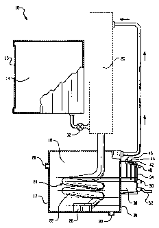
[0019] Referring to Fig. 1, a low-pressure steam cooker 10 includes a steam
generator 12
for generating steam and a cooking chamber 14 that is in communication with
the steam
generator. The cooking chamber 14 may be formed by an insulated housing and
includes an
access opening with a door 15 that is movable between open and closed
conditions. The steam
generator 12 includes a heating chamber 18 where steam is generated under
relatively low
pressure conditions (e.g., in some embodiments, at most about five psi, such
as about three psi).
As indicated by the dotted lines, in some embodiments, a steam superheater 20
may be used to
superheat steam traveling from the heating chamber 18 to the cooking chamber
14.
[0020] Disposed within the heating chamber 18 is a gas heat exchanger 22 in
the form of
a submerged heat exchange tube. As shown, heat exchanger 22 includes a helical
portion 24,
however, any suitable design can be used. The heat exchanger 22 is connected
to a burner unit
26 (e.g., a metal fiber, fan-driven burner having a stainless steel mesh and
stainless steel tube,
3
CA 02589712 2007-05-23
such as a Model BCT0027, available from N.V. Acotech S.A., Kennesaw, GA) that
is capable of
generating hot gases for delivery to the heat exchanger. Heat exchanger 22 is
located in the
heating chamber 18 such that it can be in a heat exchange relationship with
water disposed
therein. While the illustrated heat exchange relationship with the water is
via submersion of the
heat exchanger 22, it is possible that hot gas could pass through ducts that
are not submerged,
such as ducts that run along the exterior wall of the heating chamber 18.
Likewise, the heat
exchanger 22 could be in the nature of a resistive type heating element.
[0021] The heating chamber 18 includes an inlet 28 for ingress of water into
the heating
chamber from a water source (not shown) and an outlet 30 for egress of water
from the heating
chamber (as when the chamber is to be drained). A valve (not shown) is opened
and closed to
control water flow into the heating chamber, e.g., to maintain a desired water
level within the
heating chamber 18 during steam production. A valve 32 is used to control the
flow rate of
steam into the cooking chamber (in some embodiments, the flow rate of steam
into the cooking
chamber is between about 35 and about 90 pounds per hour, such as about 50
pounds per hour
where the volume of the cooking chamber is between about 164 and 245 cubic
inches).
[0022] An external probe housing unit 34 is used to monitor operating
conditions of the
steam generator 12. The external probe housing 34 is connected to an outer
surface 36 of the
steam generator 12 (such as by welding or any other suitable method) as shown.
The external
probe housing unit 34 includes a cavity 38 that is in communication with the
heating chamber
18. The communication between the cavity 38 and the heating chamber 18 allows
for passage of
water between the cavity and heating chamber and provides similar pressure and
temperature
conditions within the cavity as are present within the heating chamber.
[0023) The external probe housing unit 34 includes water level probes 42, 44
and 46 for
monitoring the water level within the cavity 38, a pressure sensor 48 for
monitoring pressure
conditions within the cavity and a temperature sensor 50 for monitoring
temperature of water
located in the cavity. The probes 42, 44, 46, the pressure sensor 48 and the
temperature sensor
50 are connected to a controller to provide a signal thereto indicative of
water level, pressure and
temperature, respectively, within the cavity. A fluid line 52 is connected to
the external probe
housing unit 34, which is used to deliver a flushing material (e.g., a scale
clean, delime release
agent) for use in breaking scale build-up from the external probe housing unit
during a flushing
operation.
4
CA 02589712 2007-05-23
[0024] Figs. 2A-2C show the external probe housing unit 34 with the water
level probes
42, 44, 46, pressure sensor 48, temperature sensor 50 and fluid line 52
removed for clarity. The
external probe housing unit 34 includes a housing part 54 forming the cavity
38 with a top 56, a
bottom 58, an open end 60, an end 62 opposite the open end and sides 64 and 66
extending
between the ends 60, 62. Located at the top 56 of the housing part 54 are
stepped portions 68, 70
and 72. Stepped portions 68, 70 and 72 each form probe receiving portions that
are offset
vertically from each other. Probe coupling members 74, 76 and 78 extend
outwardly from the
top 56 at each stepped portion 68, 70, and 72, respectively, and form openings
80, 82 and 84
(Fig. 2C) that extend through the top to provide access to the cavity 38.
While the probe
coupling members 74, 76 and 78 are illustrated as extending outwardly from the
top 56 about the
same distance, in other embodiments, the probe coupling members may extend
outwardly from
the top differing distances. Additionally, while three stepped portions 68, 70
and 72 are shown,
more or less than three stepped portions may be used.
[0025] Probe coupling members 74, 76 and 78 connect the water level probes 42,
44 and
46 to the housing part 54 with the probes extending through the respective
openings 80, 82 and
84 (see Fig. 3). Each probe coupling member 74, 76, 78 has a probe support
surface 86 (see Fig.
2C) against which respective water level probes 42, 44, 46 may be seated. Due
to the stepped
portions 68, 70 and 72, the support surfaces 86 are offset vertically from
each other with the
support surface of coupling member 74 being at a lowest elevation, the support
surface of
coupling member 76 being at an intermediate elevation and the support surface
of the coupling
member 78 being at a highest elevation. Shown most clearly by Figs. 2B and 2C,
the probe
coupling member 76 is also offset horizontally from probe members 74 and 76 to
provide
spacing between the various components located within the cavity 38. The probe
coupling
members 74, 76, 78 and their respective probe support surface 86 are used in
operatively
connecting and locating the water level probes 42, 44, 46 at desired locations
to the housing part
54.
[0026] The external probe housing unit 34 further includes sensor coupling
members 88
and 90 and fluid line coupling 92. Referring particularly to Fig. 2B, coupling
92 is offset
horizontally from the coupling members 88 and 90. The coupling members 88 and
90 and
coupling 92 are used in operatively connecting and locating the pressure
sensor 48, temperature
sensor 50 and fluid line 52 at desired locations to the housing part 54.
CA 02589712 2007-05-23
[0027] Fig. 3 shows the external probe housing unit 34 with side 64 removed to
allow for
viewing of the water level probes 42, 44, 46, pressure sensor 48 and
temperature sensor 50.
Each water level probe 42, 44, 46 includes a housing part 92, a probe part 94
and a probe length
PL that extends from a tip 96 of the respective probe part 94 up to the
respective housing part 92.
In some embodiments, the PL of each water level probe 42, 44 and 46 is
substantially equivalent
to the PL of the other water level probes. In some embodiments, the water
level probes 42, 44
and 46 may be all identical. As an example, one or more of the water level
probes may be a
Model 3L1D-XX, commercially available from Gems Sensors, Inc., Plainville, CT.
In other
embodiments, the water level probes may be different and have different probe
lengths.
[0028] Tips 96 of the water level probes 42, 44 and 46 are located at
different elevations
El, E2 and E3 within the cavity 38 and at different distances from the bottom
58 notwithstanding
that the length of each water level probe is substantially the same. This is
due to stepped
portions 68, 70 and 72 being offset vertically from each other as described
above. As can be
seen, tip 96 of water level probe 46 is located at the highest elevation E3
for detecting a HIGH
water level, tip 96 of water level probe 44 is located at an intermediate
elevation E2 for detecting
a LOW water level and tip 96 of water level probe 42 is located at a lowest
elevation El for
detecting a MINIMUM water level. As will be described below, during normal
operating
conditions the water level within the cavity is preferably maintained between
the HIGH and
LOW water levels. However, other configurations are contemplated.
[0029] Pressure sensor 48 detects pressure within the cavity 38 and is
disposed above the
tip 96 of the water level probe 46 (i.e., above the HIGH water level) during
use. Temperature
sensor 50 detects water temperature and is disposed below the tip 96 of the
water level probe 44
(i.e., below the LOW water level) during use. In some embodiments, the
temperature sensor 50
is located below the tip 96 of the water level probe 42 (i.e., below the
MINIMUM water level).
Fluid line 52 and its associated inlet 98 are located below the temperature
sensor 50 and nearest
the bottom 58. Bottom 58 is slanted downwardly from the end 62 toward the open
end 60 to
facilitate water drainage from the cavity 38 back into the heating chamber 18.
[0030] Referring now to Fig. 4, the water level probes 42, 44 and 46, the
pressure sensor
48 and the temperature sensor 50 are connected to the controller 100.
Controller 100 is capable
of controlling operation of an inlet control assembly 102 (e.g., a flow
control valve), an outlet
control assembly 104 and the water heating system 106 based, at least in part,
on signals
6
CA 02589712 2007-05-23
provided by the water level probes 42, 44, 46, pressure sensor 48 and
temperature sensor 50. In
some embodiments, controller 100 may also control operation of valve 32 (see
Fig. 1) that allows
for steam delivery to the cooking chamber 14.
[0031] Fig. 5 illustrates the external probe housing unit 34 connected to a
wall 108 of the
steam generator 12. A pair of openings 110 and 112 extending through the wall
108 provide
communication between the heating chamber 18, the open end 60 and thus cavity
38 of the
housing part 54. The openings 110 and 112 are spaced apart vertically to
provide a flow
obstruction or baffle 114 therebetween to limit the impact of turbulent water
conditions within
the chamber 18 on the water level within the cavity 38. Baffle 114 serves to
maintain a
relatively steady state within the cavity 38 despite certain conditions (e.g.,
ripples) within the
heating chamber 18, which can provide more reliable water level indications to
the controller
100 (see Fig. 4). Opening 110 is located at the bottom 58 of the housing part
54 to allow for
ingress and egress of water into and out of the cavity 38 to levels
substantially equal to that
within the heating chamber 18 during normal operation while opening 112 is
located above the
HIGH water level to allow pressure conditions within the cavity 38 to be
normally substantially
equal to that within the heating chamber. The baffle 114 is located at an
elevation corresponding
to the normal water levels of the heating chamber 18. In an alternative
embodiment, there may
be only a single, larger opening extending through the wall 108 (e.g., that is
slightly smaller than
the open end 60 of the housing part 54) that provides communication between
the cavity 38 and
the heating chamber 18.
100321 Under normal operating conditions (illustrated by Fig. 5), the water
level is
maintained between the LOW and HIGH water levels as defined by the tips 96 of
the water level
probes 44 and 46. In an exemplary control process, water level probes 42 and
44 provide an ON
signal to the controller 100 while water level probe 46 is OFF. Controller 100
includes logic
stored in memory that, based on the signals provided by the water level probes
42, 44, 46,
determines that the current water level is within normal operating conditions.
If the current
water level falls below tip 96 of the water level probe 44, controller 100
determines that the
current water level is low and can open the inlet control assembly 102 to
allow water to enter the
heating chamber 18 through the inlet 28 (Fig. 1) until the probe 44 again
provides an ON signal.
If the current water level rises above tip 96 of probe 46, the controller 100
determines that the
current water level is high and can open the outlet control assembly 104 to
allow water to drain
7
CA 02589712 2007-05-23
from the heating chamber through the outlet 30 (Fig. 1) until the probe 46 is
OFF. If the current
water level falls below tip 96 of the water level probe 42, the controller
determines that the water
level is below the MINIMUM water level and can shut down various components of
the steam
cooker 10 such as the burner 26 (Fig. 1).
[0033] As noted above, controller 100 may control other operating conditions
of the
steam cooker 10 based on input from the pressure sensor 48 and the temperature
sensor 50. For
example, if a temperature value provided by the temperature sensor 50 falls
below a certain
threshold value, controller 100 can increase the burner temperature. As
another example, if a
pressure value provided by the pressure sensor 48 rises above a certain
threshold value, the
controller may turn the burner OFF.
100341 The external probe housing unit 34 may be formed by any suitable
method. In
some embodiments, housing part 54 is formed using a sheet metal (e.g., formed
of stainless
steel). For example, referring to Fig. 6, housing part 54 is formed using
three separate sheets
114, 116 and 118, e.g., stamped or cut from a single sheet or from different
sheets. Sheet 116
may be bent to form the stepped portions 68, 70, 72, bottom 58 and end 62.
Sheets 114 and 118
may then be joined to sheet 116 by welding to form sides 64 and 66.
100351 Fig. 7 shows a variation on the external probe housing unit described
above.
External probe housing unit 120, instead of stepped portions, includes probe
coupling members
122, 124 and 126 that extend to different elevations above the top 56 of
housing part 128 with
coupling member 126 having a greatest height, coupling member 124 having an
intermediate
height and coupling member 126 having a lowest height. In a fashion similar to
that described
above, the differing heights of the coupling members 122, 124 and 126 place
tips of associated
water level probes (not shown) at different elevations within the cavity 38 of
the housing part
128.
[0036] Referring now to Figs. 8A-8C, an external probe housing unit 130
suitable for use
with a high pressure steam cooker (e.g., having operating pressures exceeding
10 psi) includes a
cast housing part 132 (e.g., formed of stainless steel). External housing unit
130 includes many
of the features described above including stepped portions 134, 136 and 138
that are used in
locating water level probes 140, 142, 144 and 146 at different heights within
cavity 148 and a
bottom 150 that is slanted downwardly toward an open end 152 of the housing
part 132. Water
8
CA 02589712 2007-05-23
level probes 140, 142, 144 and 146 provide a signal to a controller (not
shown) to maintain a
desired water level in a fashion similar to that described above.
[0037] Also supported on the stepped portions 136 and 138 are a first pressure
sensor 152
that provides an indication at a higher pressure threshold (e.g., 15 psi) and
a second pressure
sensor 154 that provides an indication at a lower pressure threshold (e.g., 13
psi). The first and
second pressure sensors 152 and 154 provide the indication to the controller
to maintain a normal
operating pressure of between the higher and lower pressure thresholds.
[0038] A flange 156 is located about a periphery of the open end 152. Flange
156
provides connecting structure so that the external probe housing unit 130 can
be fastened (e.g.,
bolted through openings 158) to a wall of a high pressure steam generator. In
some
embodiments, a sealing material such as a gasket (not shown) may be located
between the flange
156 and the wall of the high pressure steam generator to provide a fluid-tight
seal therebetween.
This arrangement can provide replaceable probe housing module that can be
removed and
replaced by a similar or identical probe housing module with relative ease. A
temperature sensor
to monitor temperature conditions within the cavity 148 and a fluid line to
deliver a flushing
fluid to the cavity may also be included (not shown).
[0039] The above-described external housing units 34, 120 and 130 provide
locating
structures that position the water level probes at different elevations within
the cavity of their
housing part. These locating structures eliminate any need to utilize water
level probes having
differing probe lengths to set HIGH, LOW and MINIMUM water levels. This can
even allow
for use of identical probes to set each of the water levels. As a further
advantage, the HIGH
water level probe, LOW water level probe and MINIMUM water level probe can be
visually
identified without any need to remove the water level probe (e.g., for a
repair operation) based
upon their elevation. For example, the water level probe located on the
highest step should be
the HIGH water level probe, the water level probe located on the intermediate
step should be the
LOW water level probe and the water level probe located on the lowest step
should be the
MINIMUM water level probe.
[0040] It is to be clearly understood that the above description is intended
by way of
illustration and example only and is not intended to be taken by way of
limitation, and that
changes and modifications are possible. Accordingly, other embodiments are
within the scope of
the following claims.
9