Note: Descriptions are shown in the official language in which they were submitted.
CA 02589962 2007-05-31
WO 2006/074242 PCT/US2006/000208
INJECTION APPARATUS HAVING A PLURALITY OF STOPPERS
BACKGROUND OF THE INVENTION
1. Field of the Invention
The present invention relates generally to medical devices and, more
particularly, to syringes and needles.
2. Description of Related Art
The term "stress urinary incontinence" refers to a functionally insufficient
urinary tract of a patient. In a patient having this condition, the tissue
relaxation of
the sphincter mechanism, located at the urinary outflow of the bladder into
the
urethra, can cause a loss of bladder control. Cystoscopes are typically used
to study
the urethra and bladder and to evaluate a patient's urinary incontinence
condition. A
typical cystoscope may comprise a tubular instrument equipped with, for
example, a
visual channel and a working channel, and constructed to be inserted through
the
urethra for viewing of the urethra and bladder. Treatment of a urinary
incontinence
condition may comprise the injection of a filler material, such as collagen,
into and
adjacent to the urinary sphincter muscle at the bladder neck, to thereby bulk
up the
tissue and assist in the adequate closure of the urinary sphincter.
Acid reflux is a digestive disorder which similarly involves the tissue
relaxation of a sphincter mechanism. In the case of acid reflux, which is
commonly
known as gastroesophageal reflux disease (GERD) or heartburn, the lower
esophageal
sphincter connecting the esophagus to the stomach begins to malfunction.
During
proper operation of the lower esophageal sphincter, the lower esophageal
sphincter
opens to allow food to pass into the stomach and closes to prevent food and
acidic
stomach fluids from flowing back up into the esophagus. Gastroesophageal
reflux
occurs when the lower esophageal sphincter is weak or relaxes inappropriately,
allowing the stomach's contents to retrograde or flow up into the esophagus.
This
retrograde flow of gastric contents back into the esophagus, through what
should be a
one-way valve into the stomach, can damage the esophagus. More particularly,
the
contents of the stomach are very acidic; and the lining of the stomach is
specially
1
CA 02589962 2007-05-31
WO 2006/074242 PCT/US2006/000208
aesignea to cope with the lower pH contents. The esophagus, on the other hand,
is
not suited for such exposure to highly acidic materials. Thus, when acid
retrogrades
from the stomach into the esophageal tissues, irritation and inflammation will
often
result to these tissues.
The severity of tissue damage which can result from gastroesophageal reflux
disease can depend on factors such as the dysfunctional level of the lower
esophageal
sphincter, the type and amount of fluid brought up from the stomach, and the
neutralizing effect of the patient's saliva. Another factor, which may affect
the
severity of a particular gastroesophageal reflux disorder, is the patient's
esophageal
motility. Lack of esophageal motility can occur through either of two
mechanisms.
When incomplete emptying of the esophagus into the stomach after ingestion of
liquids or solids occurs, the motility of the esophagus can be said to be
effected,
resulting in esophageal reflux. Also, esophageal reflux can occur when small
amounts of gastric contents, which may be refluxed into the lower esophagus,
are not
rapidly emptied back into the stomach. Delays in the emptying of this
material,
caused by an esophageal motility disorder, for example, can lead to irritation
of the
esophageal mucosa and possibly to the sensation of heartburn or the
development of
esophagitis.
Various tools and instruments have been used in the prior art for the
treatment
of types of conditions such as the above-mentioned urinary incontinence and
acid
reflux disease. Gastroscopes are typically used to study the esophagus and to
evaluate, for example, a patient's acid reflux condition. A gastroscope
typically
comprises a flexible, lighted instrument that is inserted through the mouth
and
esophagus to view the stomach. Similarly, a cystoscope is typically inserted
through
a patient's urethra to facilitate evaluation of, for example, a urinary
incontinence
condition.
A material having relatively high viscosity, such as collagen, may be injected
into the vicinity of either the lower esophageal sphincter (for acid reflux)
or the
sphincter of the urethra (for urinary incontinence) to treat either of these
disorders.
Injection procedures typically involve elongated catheters for delivery of
therapeutic
materials through body passages to target sites of injection. The force
required to
deliver a highly viscous material through a delivery lumen of an elongated
catheter
increases as the average viscosity of the material being delivered increases
and as the
length of the elongated catheter increases.
2
CA 02589962 2007-05-31
WO 2006/074242 PCT/US2006/000208
SUMMARY OF THE INVENTION
The invention herein disclosed comprises, according to one embodiment, an
injection apparatus having a first body portion with a first stopper disposed
therein.
The first body portion may be capable of receiving a first material in a
portion thereof
distal to the first stopper. The embodiment further comprises a second body
portion
operatively coupled to the first body portion. The second body portion
includes a
second stopper disposed therein. The second body portion may be capable of
receiving a second material in a portion thereon distal to the second stopper
and of
receiving the first material in a portion thereof proximal to the second
stopper.
Another embodiment of the present invention may comprise a syringe adapted
for injecting therapeutic material into a patient. The syringe may comprise a
first
body portion and a second body portion operably coupled to the first body
portion. A
first stopper may be disposed in the first body portion, the first stopper
being attached
to a plunger rod capable of moving the first stopper. The embodiment further
may
include a second stopper disposed in the second body portion.
While the apparatus and method have or will be described for the sake of
grammatical fluidity with functional explanations, it is ~to be expressly
understood that
the claims, unless expressly formulated under 35 U.S.C. 112, are not to be
construed
as necessarily limited in any way by the construction of "means" or "steps"
limitations, but are to be accorded the full scope of the meaning and
equivalents of the
definition provided by the claims under the judicial doctrine of equivalents,
and in the
case where the claims are expressly formulated under 35 U.S.C. 112 are to be
accorded full statutory equivalents under 35 U.S.C. 112.
Any feature or combination of features described herein are included within
the scope of the present invention provided that the features included in any
such
combination are not mutually inconsistent as will be apparent from the
context, this
specification, and the knowledge of one skilled in the art. For purposes of
summarizing the present invention, certain aspects, advantages and novel
features of
the present invention are described herein. Of course, it is to be understood
that not
necessarily all such aspects, advantages or features will be embodied in any
particular
embodiment of the present invention. Additional advantages and aspects of the
3
CA 02589962 2007-05-31
WO 2006/074242 PCT/US2006/000208
present invention are apparent in the following detailed description and
claims that
follow.
BRIEF DESCRIPTION OF THE FIGURES
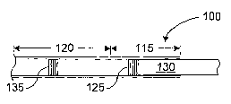
FIG. 1 is a simplified cross-sectional drawing of a portion of an injection
apparatus employing two stoppers;
FIG. 2 is a cross-section of an injection apparatus having a first stopper and
a
second stopper with the first stopper abutting the second stopper;
FIG. 3 is an illustration of an injection apparatus having two body portions,
one of which comprises an elongate catheter;
FIG. 4 is a cross-sectional diagram of an injection apparatus having two body
portions of unequal cross-section with a stopper disposed in each body
portion; and
FIG. 5 is a cross-sectional diagram of an injection apparatus having two body
portions of unequal cross-section and two stoppers disposed on one of the body
portions.
DETAILED DESCRIPTION OF THE PRESENT INVENTION
Reference will now be made in detail to the presently preferred embodiments
of the invention, examples of which are illustrated in the accompanying
drawings.
Wherever possible, the same or similar reference numbers are used in the
drawings
and the description to refer to the same or like parts. It should be noted
that the
drawings are in simplified form and are not to precise scale. In reference to
the
disclosure herein, for purposes of convenience and clarity only, directional
terms,
such as, top, bottom, left, right, up, down, over, above, below, beneath,
rear, and
front, are used with respect to the accompanying drawings. Such directional
terms
should not be construed to limit the scope of the invention in any manner.
Although the disclosure herein refers to certain illustrated embodiments, it
is
to be understood that these embodiments are presented by way of example and
not by
way of limitation. The intent of the following detailed description, although
discussing exemplary embodiments, is to be construed to cover all
modifications,
alternatives, and equivalents of the embodiments as may fall within the spirit
and
scope of the invention as defined by the appended claims. The present
invention may
4
CA 02589962 2007-05-31
WO 2006/074242 PCT/US2006/000208
be practiced in conjunction with various injection devices that are
conventionally used
in the art. For purposes of illustration, the present invention may be adapted
to an
injection device incorporating a medical injection or injection facilitation
apparatus as
disclosed in the above-referenced U.S. Patent No. 6,666,848 (the '848 patent).
As
another example, an elongated or elongated flexible syringe as described in
the above-
referenced U.S. Patent No. 6,929,623 (the '623 patent) may be modified to
include
aspects of the present invention.
Referring more particularly to the drawings, FIG. 1 is a simplified cross-
sectional drawing of a portion of an injection apparatus 100 (e.g., a syringe)
comprising a first body portion 115 and a second body portion 120. The first
body
portion 115 (e.g., chamber) is disposed proximally to the second body portion
120
(e.g., chamber), where it is understood that, as used herein, the term
"proximal" means
an end or part nearest to an operator of an instrument (e.g., the injection
apparatus
100). Conversely, the term "distal" refers to an end or part furthest from the
operator.
All figures presented herein are oriented with the proximal portions located
to the
right of distal portions, which, generally, are on the left.
In the exemplary embodiment illustrated in FIG. 1, first and second body
portions 115 and 120 form a contiguous tubular structure. First body portion
115 has
incorporated therein a first stopper 125 to which may be attached a plunger
rod 130
capable of moving the first stopper 125 in response to an applied force in a
manner
well understood in the art. Second body portion 120 may have incorporated
therein a
second stopper 135.
In a representative application, a portion of the second body portion 120 that
is
distal to the second stopper 135 may be adapted to receive a first material to
be
administered to a patient as a therapeutic agent. Examples of a first material
may
include a relatively high-viscosity material such as collagen and/or
microspheres, as is
disclosed in U.S. Patent No. 5,344,452, the contents of which are expressly
incorporated herein by reference. In the same representative application, a
portion of
the second body portion 120 that is proximal to the second stopper 135 and a
portion
of the first body portion 115 that is distal to the first stopper 125 may be
adapted to
receive a second material capable of causing movement of the second stopper
135 in,
for example, a distal direction when the first stopper 125 is moved distally.
The
second material may comprise, for example, a fluid having a relatively low
viscosity
compared, for example, to a viscosity of the first material. In modified
embodiments,
CA 02589962 2007-05-31
WO 2006/074242 PCT/US2006/000208
the second material may comprise a higher viscosity material, a gel, a
flexible solid or
semi-solid material, and/or a hard or semi-hardened material such as silicone
rubber.
In yet another embodiment, the first stopper 125 may take or resemble a shape
(and/or a functionality or the like) of one or more of the distal rod end 79
and the
driving piston 80 as shown in FIGS. 1 and 2 of the above-referenced '623
patent, even
to the extent, for example, that such element(s) may be disclosed therein as
having
different function(s). Additionally, the plunger rod 130 in the present
invention may
correspond to the movable rod 78 in FIGS. 1 and 2 of the '623 patent.
In another implementation, the plunger rod 130 can correspond to a movable
plunger 136 of, for example, an injection facilitation apparatus 17 as
disclosed in, for
example, FIG. 3 of the '848 patent and, in a further implementation, the
plunger rod
130 can be removed from the syringe (e.g., injection apparatus 100) and a
movable
rod (e.g., 113 of FIG. 3 of the '848 patent) of, for example, the injection
facilitation
apparatus 17 can be configured (e.g., sized and shaped) to operate as the
plunger rod
of the syringe (e.g., injection apparatus 100).
Indeed, according to another aspect of the present invention, a user can
remove plunger rod 130, which may correspond, for example, to a movable rod
113
or a movable plunger 136 of the injection facilitation apparatus 17 as
disclosed in
FIG. 3 of the '848 patent. In either of those or other instances, when the
first stopper
125, which may be attached to the plunger rod 130, is removed, the second
stopper
135, according to an aspect the present invention, remains in the injection
apparatus
100 to maintain a sealed (e.g., sterile) barrier to the contents disposed
distally of the
second stopper 235.
The second stopper 135 can be configured similarly to the first stopper 125 in
any suitable shape and/or of any suitable material so that the second stopper
135
maintains a sealed (e.g., sterile) barrier to the contents of the second body
portion 120
when the plunger rod 130 is removed. For example, the second stopper 135 can
take
or resemble the shape (and/or functionality, or the like) of element 99 (even
to the
extent such element may be disclosed therein as having a different function)
in FIG. 2
of the '623 patent.
FIG. 2 illustrates another aspect of the present invention wherein an
injection
apparatus 200 is provided having a first body portion 215, a second body
portion 220,
a first stopper 225 and a second stopper 235. Elements having a prefix '2' in
FIG. 2
may be configured in relation to each other as corresponding elements having a
prefix
6
CA 02589962 2007-05-31
WO 2006/074242 PCT/US2006/000208
'1' in F1G. 1. First stopper 225 in FIG. 2 has secured thereto a plunger rod
230.
According to one embodiment, plunger rod 230 comprises a male threaded portion
226 that screws into a corresponding female threaded portion disposed on a
proximal
side of the first stopper 225, thereby facilitating convenient removal of the
plunger
rod 230 from the first stopper 225.
The injection apparatus 200 may be operable to be loaded into the injection
facilitation apparatus 17 described in FIG. 3 of the above-referenced '848
patent. The
movable rod 113 in the injection facilitation apparatus 17 of FIG. 3 of the
'848 patent
may be modified to be coupled with or fitted (e.g., threaded) into the first
stopper 225
of injection apparatus 200 in place of the plunger rod 230, or in a modified
embodiment may be initially formed to comprise a first stopper (e.g., similar
to first
stopper 225) at its distal end. The first stopper 225 then may, for example,
abut with
the second stopper 235 as illustrated in FIG. 2. Alternatively, first stopper
225 may
be separated from second stopper 235 in a manner similar to the separation of
first
stopper 125 and second stopper 135 as shown in FIG. 1. Regardless of whether
first
stopper 225 abuts with second stopper 235 or is separated from second stopper
235,
the first stopper 225 may be functionally operable to move the second stopper
235. In
accordance with certain scenarios wherein, for example, the plunger rod 230 is
removably (e.g., threadably) connected to a proximal end of the first stopper
225,
removing the plunger rod 230 may in some implementations attenuate or
eliminate a
need for a second stopper. In such a case, for example, the second stopper 235
may
be reduced in size or absent.
The present invention may be configured in other ways. For example, in the
configuration illustrated in the cross-sectional view of FIG. 3, a portion of
an injection
apparatus 300 is illustrated having a first body portion 315. The first body
portion
315 has a relatively large cross-section operable to contain a first stopper
325 that is
fitted to a plunger rod 330. The injection apparatus 300 further comprises a
second
body portion 320 comprising an elongate catheter 322 having a relatively small
cross-
sectional area and operable to deliver therapeutic material to a patient. The
elongate
catheter 322 may be fitted with a second stopper 335. The second body portion
320 is
operatively coupled to the first body portion 315 by which is meant that the
second
body portion 320 is fluidly coupled to the first body portion 315, so that
material (e.g.,
a fluid) is able to pass between the first body portion 315 and the second
body portion
320. The transition between the first body portion 315 and the second body
portion
7
CA 02589962 2007-05-31
WO 2006/074242 PCT/US2006/000208
322 may comprise a rapid transition between diameters as shown or may in
modified
embodiments comprise one or more gradual transitions between the two diameters
to
facilitate, for example, relatively low-resistance movement of fluid between
the first
body portion 315 and the second body portion 322.
A first material may be disposed in a movable portion of the injection
apparatus 300 lying proximal to the second stopper 335 and distal to the first
stopper
325. A second material may occupy a portion of the elongate catheter 3221ying
distal
to the second stopper 335. The second stopper 335 thereby may provide a
movable
barrier (i.e., a seal) between the first material and the second material. The
elongate
catheter 322 may be fitted with a hollow needle 323 that may, in some
applications,
be used to inject the second material into a patient.
According to one example, the first material (e.g., a saline solution) has a
relatively low viscosity so that relatively little force need be applied to
the plunger rod
330 in order to cause distal movement of the first stopper 325. Moving the
first
stopper 325 distally can increase pressure applied to a proximal side of the
second
stopper 335, thereby tending to cause the second stopper 330 to move distally,
which
movement may cause, for example, therapeutic material (e.g., the second
material) to
pass from the elongate catheter 322 through the hollow needle 323 and into
tissue of a
patient.
FIG. 4 is a cross-sectional schematic of yet another injection apparatus 400
depicting an embodiment of the present invention. The injection apparatus 400,
as
illustrated, comprises a first body portion 415 having, for example, a
circular cross-
section characterized by an inner diameter. The injection apparatus 400
further
comprises a second body portion 420 having, for example, a circular cross-
section
characterized by an inner diameter less than the inner diameter of the first
body
portion 415. A first stopper 425 is disposed within the first body portion
415, and a
second stopper 435 is disposed within the second body portion 420. A plunger
rod
430 may be secured to a proximal side of the first stopper 425. In operation,
a first
material may occupy a portion of the injection apparatus 400 disposed distally
of the
first stopper 425 and proximally of the second stopper 435. A second material
may
occupy a portion of the injection apparatus 400 disposed distally of the
second stopper
435 in a manner similar to that already described above with reference to
FIGS. 1-3.
According to another implementation of the present invention, an embodiment
as illustrated in FIG. 5 can comprise an injection apparatus 500 having a
first body
8
CA 02589962 2007-05-31
WO 2006/074242 PCT/US2006/000208
portion 515 with an inner diameter and a second body portion 520 with an inner
diameter that is less than the inner diameter of the first body portion 515.
The
injection apparatus 500 further comprises a first stopper 525 and a second
stopper
535, both of which are disposed in the first body portion 515. A plunger rod
530 may
be secured to a proximal side of the first stopper 525. As is the case with
the
embodiment illustrated in FIG. 4, the embodiment of FIG. 5 may accommodate a
first
material within a portion of the first body portion 515 located distally of
first stopper
525 and proximally of the second stopper 535. A second material (e.g., a
therapeutic
material suitable for injection into tissue of a patient) may occupy at least
part of the
second body portion 520 and at least part of the first body portion 515 that
is located
distally of the second stopper 535.
In view of the foregoing, it will be understood by those skilled in the art
that
the methods and devices of the present invention can facilitate formation of
injection
apparatuses. The above-described embodiments have been provided by way of
example, and the present invention is not limited to these examples. Multiple
variations and modification to the disclosed embodiments will occur, to the
extent not
mutually exclusive, to those skilled in the art upon consideration of the
foregoing
description. For example, the first body portions of the examples described
herein
may have cross-sections smaller than cross-sections of the second body
portions.
Body portions may have cross-sections that are substantially circular,
elliptical,
rectangular, or the like, or that take other types of shapes altogether.
Transitions
between first body portions and second body portions may be abrupt as
illustrated
herein, or graduated (e.g., tapered) to facilitate, for example, inter-body-
portion fluid
flow. Bevels and/or chamfers, for example, may be introduced as disclosed, for
example, in the above-referenced '848 patent. While exemplary embodiments
having
two body portions, two stoppers and/or two diameters (e.g., the same or
different)
have been disclosed herein, other embodiments in accordance with the present
invention may comprise, for example, three or more body portions, three or
more
stoppers and/or three or more diameters (e.g., the same or different).
Additionally,
other combinations, omissions, substitutions and modifications will be
apparent to the
skilled artisan in view of the disclosure herein. Accordingly, the present
invention is
not intended to be limited by the disclosed embodiments, but is to be defined
by
reference to the appended claims.
9