Language selection

Search

Patent 2590272 Summary

Third-party information liability

Some of the information on this Web page has been provided by external sources. The Government of Canada is not responsible for the accuracy, reliability or currency of the information supplied by external sources. Users wishing to rely upon this information should consult directly with the source of the information. Content provided by external sources is not subject to official languages, privacy and accessibility requirements.

Claims and Abstract availability

Any discrepancies in the text and image of the Claims and Abstract are due to differing posting times. Text of the Claims and Abstract are posted:

  • At the time the application is open to public inspection;
  • At the time of issue of the patent (grant).
(12) Patent Application: (11) CA 2590272
(54) English Title: DUMBBELL ADJUSTING SYSTEM
(54) French Title: SYSTEME DE REGLAGE D'HALTERES
Status: Deemed Abandoned and Beyond the Period of Reinstatement - Pending Response to Notice of Disregarded Communication
Bibliographic Data
(51) International Patent Classification (IPC):
  • A63B 21/075 (2006.01)
(72) Inventors :
  • DOUDIET, ADAM T. (United States of America)
(73) Owners :
  • ATD SERVICES, LLC
(71) Applicants :
  • ATD SERVICES, LLC (United States of America)
(74) Agent: SMART & BIGGAR LP
(74) Associate agent:
(45) Issued:
(86) PCT Filing Date: 2005-12-13
(87) Open to Public Inspection: 2006-06-22
Availability of licence: N/A
Dedicated to the Public: N/A
(25) Language of filing: English

Patent Cooperation Treaty (PCT): Yes
(86) PCT Filing Number: PCT/US2005/045174
(87) International Publication Number: WO 2006065864
(85) National Entry: 2007-06-12

(30) Application Priority Data:
Application No. Country/Territory Date
60/635,876 (United States of America) 2004-12-13

Abstracts

English Abstract


A dumbbell adjusting system comprises an adjusting system, a stand, and a
locking mechanism. The adjusting system includes two rods on the dumbbell's
handle which move in and out of the handle to selectively engage the inner
threaded through holes of the weights. The weights are configured to interlock
with one another so as not to move independently. The locking mechanism
unlocks the weights from the handle when the dumbbell is in the stand,
allowing the user to select the desired weight, and locks the weights into the
handle when the dumbbell is lifted out of the stand.


French Abstract

L'invention concerne un système de réglage d'haltères qui comprend un système de réglage, un support, et un mécanisme de verrouillage. Le système de réglage comporte deux tiges installées sur la poignée de l'haltère qui se déplacent dans et hors de ladite poignée de façon à mettre en prise sélectivement les trous filetés traversants internes des poids. Ces derniers sont configurés de façon à se verrouiller les uns aux autres et à ne pas bouger de manière indépendante. Le mécanisme de verrouillage débloque les poids de la poignée lorsque l'haltère est sur le support, ce qui permet à l'utilisateur de choisir le poids désiré, et bloque les poids dans la poignée lorsque l'haltère est soulevé hors du support.

Claims

Note: Claims are shown in the official language in which they were submitted.

WHAT IS CLAIMED IS:
1. A dumbbell system providing user selected weight comprises:
a tube having an inner axial passage and an outer surface adapted for manual
grasping;
two externally threaded rods having external threads and being mounted to
axially translate within the axial passage, wherein the rods are coupled to
the tube so that
rotation of the tube causes rotation of the rods; and
a plurality of weights having threaded center holes and arranged successively
on each end of the tube, wherein rotation causes the threads of the rods to
engage the
threaded center holes to advance the rods into the center holes of the
weights.
2. The system of claim 1, wherein said weights have slots and strips to
interlock with each other.
3. The dumbbell adjusting system of claim 1, further comprises a stand
which receives and immobilizes the weights while the tube is rotated.
4. A system as in claim 1, further comprises a locking mechanism
comprising:
a spring and a bullet for engaging an inside weight to prevent rotation of
said
weights while the tube is rotated.
5. A system as in claim 4, wherein the stand comprises slots to stabilize
said weights and two latches.
6. A method for adjusting the weight of each end of a dumbbell, said
method comprising:
providing a dumbbell including a tube handle and a plurality of weights on
each end; and
turning the tube handle to axially advance or retract rods into each of the
plurality of weights, wherein the number of weights engaged by the rods is
always the same
on each end.

Description

Note: Descriptions are shown in the official language in which they were submitted.


CA 02590272 2007-06-12
WO 2006/065864 PCT/US2005/045174
DUMBBELL ADJUSTING SYSTEM
BACKGROUND OF THE INVENTION
[0001] 1. Field of the Invention. The present invention relates generally to
an exercise
device. and more particularly to an adjustable dumbbell.
[0002] U.S. Pat No. 6,500,101 discloses an adjustable dumbbell comprising two
rotating
rods that move into and out of through holes of weights by means of a
selection knob
mounted on a carrying seat. The weights are held by the carrying seat by means
of two
connection rods held between the weights on opposite ends of the dumbbell.
[0003] The connection rods, the four grip rods around the central handle, and
the selection
device mounted on the carrying seat make the dumbbell bulky and cumbersome to
use. They
also limit flexibility in the user's wrist which is a problem in exercises
that stimulate the
forearm. Lastly, the bulkiness detracts from the traditional aesthetic look of
a regular
duinbbell of a handle and weights on the ends.
[00041 2. Description of the Background Art. Adjustable dumbbell systems are
described in U.S. Patent Nos. 5,090,693; 5,464,379; 5,628,716; 6,149,558; and
6,500,101;
and U.S. Published Application No. 2003/0148862.
BRIEF SUMMARY OF THE INVENTION
[0005] The present invention selectively engages and releases weights from a
tube with two
inner rods without a carrying seat making it safer to use and allowing for
full mobility. It
comprises of 1) an adjusting system, 2) a stand, and 3) a locking mechanism.
The adjusting
system relies on rotating the dumbbell's handle which then moves the rods in
and out of the
handle and engages/disengages tluough holes of the weiglits. The locking
mechanism
unlocks the weights from the handle when the dumbbell is lowered into the
stand and
prevents the dumbbell from being lifted from the stand until the desired
number of weights
are fully loaded.
[0006] In a first aspect, the present invention comprises a dumbbell system
which allows
for a particularly convenient mechanism for user weight adjustment. The
mechanism can be
adjusted with a single hand and allows the user to effect adjustment in a
single motion
immediately prior to lifting the weight from an associated storage stand. The
dumbbell

CA 02590272 2007-06-12
WO 2006/065864 PCT/US2005/045174
2
system comprises a tube having an inner axial passage and outer surface
adapted for manual
grasping. The tube will serve as the handle for the dumbbell, and will have a
pair of
externally threaded rods mounted to axially translate in opposite directions
from openings at
either end of the tube handle. The rods will be mounted so that they will
rotate in response to
rotation of the handle (typically being coupled by slotted stop ends which
ride on an
adjustment rail formed on the inner surface of the tube handle), and a
plurality of weights
having threaded center holes will be disposed at either end of the tube
handle. The weights
will be arranged successively and held, usually in the associated stand, so
that rotation of the
tube will selectively cause each of the rods to engage the tlu=eaded center
holes and advance
into the center holes of the weights, typically by a distance which can be
observed through a
window on the tubular handle. In this way, the user can rotate the handle,
such that and until
each of the externally threaded rods enters the weights and engages the
weights via the
threads. When a desired number of weights have been engaged on each side,
typically an
equal number so that the dumbbell is syinmetrically loaded, the user can stop
rotating the
handle and lift the dumbbell from the stand for use.
[0007] In preferred embodiments, the weights will have slots and strips which
interlock
with each other so that adjacent weights cannot rotate relative to each other.
The system will
preferably further comprise the stand, and the stand will be adapted to
receive and
immobilize the weights while the tube is being rotated within the dumbbell
system. The
system will further preferably comprise a locking mechanism including a spring
and a bullet
for engaging an inside weight to prevent rotation of the plurality of weights
when the
dumbbell is out of the stand and in use.
[0008] In another aspect of the present invention, a method for adjusting the
weight on each
end of the dumbbell comprises providing a dumbbell having a tube handle and a
plurality of
weight on each end. The weights are adjusted by turning the tube handle to
axially advance
or retract rods from the handle into each of the plurality of weights such
that the number of
weights engaged by the rods is always the same on each end of the handle. In
this way, the
user can rotate the handle until a desired number of weights are engaged and
then lift the
handle from an associate stand or other receptacle for use.
BRIEF DESCRIPTION OF THE DRAWINGS
[0009] Fig. 1 is an overview of the dumbbell.

CA 02590272 2007-06-12
WO 2006/065864 PCT/US2005/045174
3
[0010] Fig. 2 is an overview of the stand.
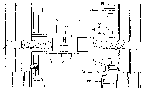
[0011] Fig. 3 is a sectional view of the dumbbell.
[0012] Fig. 4 is a view of the tube from end.
[0013] Fig. 5 are rotary rods.
[0014] Fig. 6a is a view of the inside surface of weight.
[0015] Fig. 6b is a view of the outside surface of weiglit.
[0016] Fig. 7 is an inside view (facing toward handle) of the first half of
locking structure.
[0017] Fig. 8 is an outside view (facing away from handle) of the first the
half of locking
sti-ucture.
[0018] Fig. 9 is an outside view (facing away from handle) of the second half
of locking
structure.
[0019] Fig. 10 is an inside view (facing toward handle) of the second half of
locking
stiucture.
[0020] Fig. 11 are inserts into hole in bullet.
[0021] Fig. 12 is a retaining ring shown attached to the inside surface of
weight.
DETAILED DESCRIPTION OF THE INVENTION
[0022] A tube 30 (Figs. 1 and 4) has one or more rails 31 attached lengthwise
along an
inside surface of the tube. Two rotating rods 32 with stop ends 33 are
confoimed to fit inside
an axial passage in the tube 30. The passage preferably has a non-circular
cross-section
which conforms to the outer periphery of the stop ends 33. An indicator line
55 on the stop
end 33 (Fig. 5) of either of the two rotary rods 32 appears through a display
window 56 in the
tube 30. The indicator line 55 moves axially to selection numbers 57 that
appear alongside
the display window 56 on the outside surface of the tube 30 as the tube is
manually rotated,
as described in more detail below. Weights 34 with internally threaded through
holes 35 are
engaged by the rotary rods 32. At least one weight on each end of the tube 30
is engaged at
all times. The outside surface of each weight, with the exception of the
outside weights
furthest from the tube 30, has a slot 36 (Fig. 6b). The inside surface of each
weight, with the
exception of the inside weights closest to the tube 30, has a strip 37 (Fig.
6a). The strips 37
~

CA 02590272 2007-06-12
WO 2006/065864 PCT/US2005/045174
4
of each weight fit into the slots 36 of the next weight to couple adjacent
weights so that each
weight engaged by the rotary rods 32 cannot move independently of each other.
In addition,
there is a hole 38 (Fig. 3) on the inside surface of each of the inside
weights.
[0023] A locking structure 39, as shown in Fig. 3, is attached to each of the
outer ends of
the tube 30. The locking structure 39 consists of two halves. One half 40
contains a hole 41
(Figs. 7 and 8) through which to fit the tube 30 and a second hole 42 (Fig. 8)
through which a
locking bullet 47 enters the hole 38 in the inside weight. The other half 43
(Fig. 10) contains
a hole 44 (Fig. 9) tlirough which to fit the tube 30 and a container 45 and
pin 46 (Fig. 3) to
guide the locking bullet 47 and a spring 48.
[0024] Attached to the inside surface of the inside weights is a retaining
ring 49 (Fig. 12)
into which the locking structure 39 fits. The retaining ring 49 keeps the
inside weigllts from
separating from the tube 30 at all times.
[0025] A stand 50 (Fig. 2) comprises two compartments or brackets 51 to hold
the two sets
of weights (one on each end of the dumbbell). The compartments 51 contain
retaining fins
52 which define slots to receive and to maintain the weights 34 upright and
parallel to each
other. On the surface of the stand 50 are latches 53.
[0026] When the dumbbell is lowered into the stand 50 (Fig. 2), each latch 53
compresses
the spring 48 (Fig. 3) by contacting the angled fin 54 on the locking bullet
47 (Fig. 11). This
disengages the locking bullet 47 fi=om the hole 38 of the inside weights so
only the rounded
head of the locking bullet 47 remains in the hole 38. When the user rotates
the tube 30, the
locking bullet 47 fully disengages the hole 38 in the inside weight. The latch
53 (Fig. 3) is
also enclosed by the locking structure 39, restricting the dumbbell from being
lifted until the
tube 30 has niade one complete rotation. When the tube 30 is rotated, the
rotary rods 32 also
rotate by force of the rails 31 and the non-circular geometry of the stop ends
33 and engage or
disengage the througli holes 35 of the weights 34.

Representative Drawing
A single figure which represents the drawing illustrating the invention.
Administrative Status

2024-08-01:As part of the Next Generation Patents (NGP) transition, the Canadian Patents Database (CPD) now contains a more detailed Event History, which replicates the Event Log of our new back-office solution.

Please note that "Inactive:" events refers to events no longer in use in our new back-office solution.

For a clearer understanding of the status of the application/patent presented on this page, the site Disclaimer , as well as the definitions for Patent , Event History , Maintenance Fee  and Payment History  should be consulted.

Event History

Description Date
Time Limit for Reversal Expired 2011-12-13
Application Not Reinstated by Deadline 2011-12-13
Inactive: Abandon-RFE+Late fee unpaid-Correspondence sent 2010-12-13
Deemed Abandoned - Failure to Respond to Maintenance Fee Notice 2010-12-13
Letter Sent 2008-02-19
Reinstatement Requirements Deemed Compliant for All Abandonment Reasons 2008-01-24
Deemed Abandoned - Failure to Respond to Maintenance Fee Notice 2007-12-13
Letter Sent 2007-11-05
Inactive: Single transfer 2007-09-12
Inactive: Cover page published 2007-08-30
Inactive: Notice - National entry - No RFE 2007-08-28
Inactive: First IPC assigned 2007-07-05
Application Received - PCT 2007-07-04
National Entry Requirements Determined Compliant 2007-06-12
Application Published (Open to Public Inspection) 2006-06-22

Abandonment History

Abandonment Date Reason Reinstatement Date
2010-12-13
2007-12-13

Maintenance Fee

The last payment was received on 2009-11-23

Note : If the full payment has not been received on or before the date indicated, a further fee may be required which may be one of the following

  • the reinstatement fee;
  • the late payment fee; or
  • additional fee to reverse deemed expiry.

Please refer to the CIPO Patent Fees web page to see all current fee amounts.

Fee History

Fee Type Anniversary Year Due Date Paid Date
Basic national fee - standard 2007-06-12
Registration of a document 2007-09-12
MF (application, 2nd anniv.) - standard 02 2007-12-13 2008-01-24
Reinstatement 2008-01-24
MF (application, 3rd anniv.) - standard 03 2008-12-15 2008-09-16
MF (application, 4th anniv.) - standard 04 2009-12-14 2009-11-23
Owners on Record

Note: Records showing the ownership history in alphabetical order.

Current Owners on Record
ATD SERVICES, LLC
Past Owners on Record
ADAM T. DOUDIET
Past Owners that do not appear in the "Owners on Record" listing will appear in other documentation within the application.
Documents

To view selected files, please enter reCAPTCHA code :


To view images, click a link in the Document Description column. To download the documents, select one or more checkboxes in the first column and then click the "Download Selected in PDF format (Zip Archive)" or the "Download Selected as Single PDF" button.

List of published and non-published patent-specific documents on the CPD .

If you have any difficulty accessing content, you can call the Client Service Centre at 1-866-997-1936 or send them an e-mail at CIPO Client Service Centre.


Document
Description 
Date
(yyyy-mm-dd) 
Number of pages   Size of Image (KB) 
Drawings 2007-06-12 12 127
Description 2007-06-12 4 219
Claims 2007-06-12 1 39
Abstract 2007-06-12 1 75
Representative drawing 2007-08-29 1 20
Cover Page 2007-08-30 1 51
Reminder of maintenance fee due 2007-08-28 1 112
Notice of National Entry 2007-08-28 1 195
Courtesy - Abandonment Letter (Maintenance Fee) 2008-02-07 1 176
Notice of Reinstatement 2008-02-19 1 167
Courtesy - Certificate of registration (related document(s)) 2007-11-05 1 104
Reminder - Request for Examination 2010-08-16 1 120
Courtesy - Abandonment Letter (Maintenance Fee) 2011-02-07 1 172
Courtesy - Abandonment Letter (Request for Examination) 2011-03-21 1 164
PCT 2007-06-12 2 90
Correspondence 2007-08-28 1 26
PCT 2007-10-25 1 45