Note: Descriptions are shown in the official language in which they were submitted.
CA 02590439 2010-05-26
DRILL BIT WITH ASYMMETRIC GAGE PAD CONFIGURATION
BACKGROUND
Field of the Invention
The invention relates generally to earth-boring bits used to drill a borehole
for the ultimate
recovery of oil, gas, or minerals. More particularly, the invention relates to
drill bits designed to
shift the orientation of its axis in a predetermined direction as it drills.
Still more particularly, the
invention relates to a drill bit having inclination reducing or "dropping"
tendencies.
Background of the Invention
An earth-boring drill bit is typically mounted on the lower end of a drill
string and is
rotated by rotating the drill string at the surface or by actuation of
downhole motors or turbines, or
by both methods. With weight applied to the drill string, the rotating drill
bit engages the earthen
formation and proceeds to form a borehole along a predetermined path toward a
target zone. The
borehole thus created will have a diameter generally equal to the diameter or
"gage" of the drill bit.
Many different types of drill bits and cutting structures for bits have been
developed and
found useful in drilling such boreholes. Two predominate types of rock bits
are roller cone bits
and fixed cutter (or rotary drag) bits. Many fixed cutter bit designs include
a plurality of blades
that project radially outward from the bit body and form flow channels there
between. Typically,
cutter elements are grouped and mounted on the several blades.
The cutter elements disposed on the several blades of a fixed cutter bit are
typically formed
of extremely hard materials and include a layer of polycrystalline diamond
("PD") material. In the
CA 02590439 2010-05-26
typical fixed cutter bit, each cutter element or assembly comprises an
elongate and generally
cylindrical support member which is received and secured in a pocket formed in
the surface of one
of the several blades. A cutter element typically has a hard cutting layer of
polycrystalline
diamond or other superabrasive material such as cubic boron nitride, thermally
stable diamond,
polycrystalline cubic boron nitride, or ultrahard tungsten carbide (meaning a
tungsten carbide
material having a wear-resistance that is greater than the wear-resistance of
the material forming
the substrate) as well as mixtures or combinations of these materials. The
cutting layer is exposed
on one end of its support member, which is typically formed of tungsten
carbide. For convenience,
as used herein, reference to "PD bit" or "PD cutter element" refers to a fixed
cutter bit or cutter
element employing a hard cutting layer of polycrystalline diamond or other
superabrasive material
such as cubic boron nitride, thermally stable diamond, polycrystalline cubic
boron nitride, or
ultrahard tungsten carbide.
While the bit is rotated, drilling fluid is pumped through the drill string
and directed out of
the drill bit. The fixed cutter bit typically includes nozzles or fixed ports
spaced about the bit face
that serve to inject drilling fluid into the flow passageways between the
several blades. The
flowing fluid performs several important functions. The fluid removes
formation cuttings from the
bit's cutting structure. Otherwise, accumulation of formation materials on the
cutting structure may
inhibit or prevent the penetration of the cutting structure into the
formation. In addition, the fluid
removes cut formation materials from the bottom of the borehole. Failure to
remove formation
materials from the bottom of the borehole may result in subsequent passes by
the cutting structure
to re-cut the same materials, thus reducing cutting rate and potentially
increasing wear on the
cutting surfaces. The drilling fluid and cuttings removed from the bit face
and from the bottom of
the borehole are forced and carried to the surface through the annulus that
exists between the drill
2
CA 02590439 2010-05-26
string and the borehole sidewall. Still further, the drilling fluid removes
frictional heat from the
cutter elements in order to prolong cutter element life. Thus, the number and
placement of drilling
fluid nozzles, and the resulting flow of drilling fluid, may significantly
impact the performance of
the drill bit.
Depending on the location and orientation of the target formation or pay zone,
directional
drilling (e.g., horizontal drilling) with the drill bit may be desired. In
general, directional drilling
involves deviation of the borehole from vertical (i.e., drilling a borehole in
a direction other than
substantially vertical), and is typically accomplished by drilling, for at
least some period of time, in
a direction not parallel with the bit axis. Directional drilling capabilities
have improved as
advancements in measurement while drilling (MWD) technologies have enabled
drillers to better
track the position and orientation of the wellbore. In addition, more
extensive and more accurate
information about the location of the target formation as a result of improved
logging techniques
has enhanced directional drilling capabilities. As directional drilling
capabilities have improved,
so have the expectations for drilling performance. For example, a driller
today may target a
relatively narrow, horizontal oil-bearing stratum, and may wish to maintain
the borehole
completely within the stratum. In some complex scenarios, highly specialized
"design drilling"
techniques with highly tortuous well paths having multiple directional changes
of two or more
bends lying in different planes may be employed.
One common method to control the drilling direction of a bit is to steer the
bit using a
downhole motor with a bent sub and/or housing. As shown in Figure 1, a
simplified version of a
downhole steering system according to the prior art comprises a rig 1, a drill
string 2 having a
downhole motor 6 with a bent sub 4, and a conventional drill bit 8. Motor 6
and bent sub 4 form
part of the bottomhole assembly (BHA) and are attached to the lower end of the
drill string 2
3
CA 02590439 2010-05-26
adjacent the conventional drill bit 8. When not rotating, the bent sub 4
causes the bit face to be
canted with respect to the tool axis. The downhole motor 6 is capable of
rotating conventional drill
bit 8 without the need to rotate the entire drill string 2. For example,
downhole motor 6 may be a
turbine, an electric motor, or a progressive cavity motor that converts
drilling fluid pressure
pumped down drill string 2 into rotational energy at drill bit 8. When
downhole motor 6 is used
with bent sub 6 without rotating drill string 2, drill bit 8 drills a borehole
that is deviated in the
direction of the bend or curve in the bent sub 6. On the contrary, when the
drill string is also
rotated, the borehole normally maintains a linear path or direction, even when
a downhole motor is
used, since the bent sub or housing rotates along with the drill string, and
thus, no longer orients
the drill bit in a specific direction. Consequently, a combination of a bent
sub or housing and a
downhole motor to rotate the drill bit without rotating the still string
generally provide a more
effective means for deviating a borehole.
When a well is deviated from vertical by several degrees and has a substantial
inclination,
such as greater than 30 degrees, the factors typically influencing drilling
and steering may have a
reduced impact. For instance, operational parameters such as weight on bit
(WOB) and RPM
typically have a large influence on the bit's ROP, as well as its ability to
achieve and maintain the
required well bore trajectory. However, as the inclination of the well
increases towards horizontal,
it becomes more difficult to apply weight on bit effectively since the
borehole bottom is no longer
aligned with the force of gravity - increasing bends in the drill string tend
to reduce the amount of
downward force applied to the string at the surface that is translated to WOB
acting at the bit face.
In some cases, the application of sufficient downward forces at the surface to
a bent drill string
may lead to buckling or deformation of the drill string. Consequently,
directional drilling with a
4
CA 02590439 2010-05-26
combination of a downhole motor and a bent sub may decrease the effective WOB,
and thus, may
reduce the achievable ROP.
In addition, as previously described, directional drilling with a downhole
motor coupled
with a bent sub is preferably performed without rotating the drill string in a
process commonly
referred to as "sliding." However, in drilling operations where the drill
string is not rotating, or is
rotated very little, the rotational shear acting on the drilling fluid in the
annulus between the drill
string and borehole wall is decreased, as compared to a case where the entire
drill string is rotating.
Since drilling fluids tend to be thixotropic, the reduction or complete loss
of the shearing action
tends to adversely affect the ability of the drilling fluid to flush and carry
away cuttings from the
borehole. As a result, in deviated holes drilled with a downhole motor and
bent sub alone,
formation cuttings are more likely to settle out of the drilling fluid on the
bottom or low side of the
borehole. This may increase borehole drag, making weight-on-bit transmission
to the bit even
more difficult, and often resulting in tool phase control and prediction
problems. These challenges
encountered in sliding can result in an inefficient and time consuming
operation.
Still further, drilling with the downhole motor and bent sub during a sliding
operation
deprives the driller of the use of a significant source of rotational energy
and power, namely the
surface equipment that is otherwise employed to rotate the drill string. In
directional drilling cases
employing a downhole motor powered by drilling fluid pressure (e.g.,
progressive cavity motor),
the large pressure drop across the downhole motor consumes a significant
portion of the energy of
the drilling fluid, and may detrimentally reduce the hydraulic capabilities of
the drilling fluid
advanced to the bit face and borehole bottom. In other words, the large
pressure drop across the
motor results in a lower drilling fluid pressure at the bit face, potentially
decreasing the ability of
the drilling fluid to clean and cool the cutter elements on the bit face, and
flush away cutting from
5
CA 02590439 2010-05-26
the borehole bottom. To the contrary, when surface equipment is employed to
rotate the drill string
and the bit, rotational energy and power are directly translated to the bit,
without the need to
convert drilling fluid pressure to rotational energy. Consequently, the use of
surface equipment to
rotate a drill string and bit may result in increased ROP and improved bit
hydraulics as compared
to a bit rotated by a downhole motor alone.
In addition to deviating from vertical in directional drilling operations as
shown in Figure
1, it may also be desirable to have a drill bit capable of returning to a
vertical drilling orientation in
the event the drill bit inadvertently deviates from vertical. The ability of a
bit to return to a vertical
path after deviating from such a path is generally referred to as "dropping".
In order to effect
dropping, a drill bit must have the capability of drilling or penetrating the
earth in a direction not
parallel with the longitudinal axis of the bit.
As shown in the schematic view of Figure 2, a drillstring assembly 50
including a drill
string 53 and a bit 51 is shown drilling a borehole 55 that has deviated from
vertical. Drillstring
assembly 50 has a weight vector 52 that consists of an axial component 54 and
a radial or normal
component 56. Unlike the directional drilling operations described above in
which deviations from
vertical are desired, in some cases, deviations from vertical are
unintentional or inadvertent. In
such cases, it may be desirable to return drilling assembly 50 to a vertical
orientation while drilling.
To effect such a return to vertical, drill bit 51 must drill in a direction
that is not parallel to axial
vector 54. This may be accomplished by cutting and removing formation material
from a sidewall
57 of borehole 55.
Accordingly, there remains a need in the art for an apparatus or system
capable of altering
the azimuth or inclination of a drill bit and well without relying solely on a
downhole motor or
6
CA 02590439 2010-05-26
rotary steerable device. Such an apparatus would be particularly well received
if it was capable of
altering the direction of the drill string and borehole trajectory in a
controlled manner while
maintaining the rotation of the entire drill string. In addition, it is
desired that this change in
direction be achieved with a drill bit having predetermined dropping
tendencies, regardless of
formation type, lithology, well trajectory, stratigraphy, or formation dip
angles.
BRIEF SUMMARY OF SOME OF THE PREFERRED EMBODIMENTS
In accordance with at least one embodiment of the invention, a drill bit for
drilling a
borehole in earthen formations comprises a bit body having a bit axis and a
bit face. In addition,
the bit comprises a pin end extending from the bit body opposite the bit face.
Further, the bit
comprises a plurality of gage pads extending from the bit body, wherein each
gage pad includes a
radially outer gage-facing surface. The gage-facing surfaces of the plurality
of gage pads define a
gage pad circumference that is centered relative to a gage pad axis, the gage
pad axis being
substantially parallel to the bit axis and offset from the bit axis.
In accordance with other embodiments of the invention, a drill bit for
drilling a borehole
comprises a bit body having a bit axis and a bit face including a cone region,
a shoulder region, and
a gage region. In addition, the bit comprises a pin end opposite the face
region. Further the bit
comprises a first blade and a second blade, each blade radially extending
along the bit face and
having a first end in the cone region and a second end in the gage region.
Still further, the bit
comprises a first gage pad having a gage-facing surface and extending from the
second end of the
first blade. Moreover, the bit comprises a second gage pad having a gage-
facing surface and
extending from the second end of the second blade. The gage-facing surface of
the first gage pad
7
CA 02590439 2010-05-26
and the gage-facing surface of the second gage pad are each substantially
equidistant from a gage
pad axis that is offset from the bit axis.
In accordance with another embodiment of the invention, a drill bit for
drilling a borehole
having a predetermined full gage diameter comprises a bit body having a bit
axis and a bit face. In
addition, the bit comprises a pin end extending from the bit body opposite the
bit face, the pin end
being concentric about the bit axis. Further, the bit comprises a cutting
structure on the bit face
extending to the full gage diameter. Still further, the bit comprises a
plurality of N1 gage pads
disposed about the bit body, each of the N1 gage pads including a gage-facing
surface, wherein the
gage-facing surfaces on the Ni gage pads are concentric about a gage pad axis
that is parallel to the
bit axis and offset from the bit axis.
Thus, embodiments described herein comprise a combination of features and
advantages
intended to address various shortcomings associated with certain prior
devices. The various
characteristics described above, as well as other features, will be readily
apparent to those skilled in
the art upon reading the following detailed description of the preferred
embodiments, and by
referring to the accompanying drawings.
BRIEF DESCRIPTION OF THE DRAWINGS
For a more detailed description of the preferred embodiments, reference will
now be made
to the accompanying drawings, wherein:
Figure 1 is a schematic view of a conventional drilling system;
Figure 2 is a schematic view of a prior art drill bit on a drill string;
Figure 3 is a perspective view of an embodiment of a bit made in accordance
with the
principles described herein;
8
CA 02590439 2010-05-26
Figure 4 is a partial cross-sectional view of the bit shown in Figure 3 with
the cutter
elements of the bit shown rotated into a single profile;
Figure 5 is an axial cutting face end view of the drill bit of Figure 3; and
Figure 6 is an axial pin end view of the drill bit of Figure 3.
DETAILED DESCRIPTION OF SOME OF THE PREFERRED EMBODIMENTS
The following discussion is directed to various embodiments. Although one or
more of
these embodiments may be preferred, the embodiments disclosed should not be
interpreted, or
otherwise used, as limiting the scope of the disclosure, including the claims.
In addition, one
skilled in the art will understand that the following description has broad
application, and the
discussion of any embodiment is meant only to be exemplary of that embodiment,
and not intended
to intimate that the scope of the disclosure, including the claims, is limited
to that embodiment.
Certain terms are used throughout the following description and claims to
refer to particular
features or components. As one skilled in the art will appreciate, different
persons may refer to the
same feature or component by different names. This document does not intend to
distinguish
between components or features that differ in name but not function. The
drawing figures are not
necessarily to scale. Certain features and components herein may be shown
exaggerated in scale
or in somewhat schematic form and some details of conventional elements may
not be shown in
interest of clarity and conciseness.
In the following discussion and in the claims, the terms "including" and
"comprising" are
used in an open-ended fashion, and thus should be interpreted to mean
"including, but not limited
to... ." Also, the term "couple" or "couples" is intended to mean either an
indirect or direct
9
CA 02590439 2010-05-26
connection. Thus, if a first device couples to a second device, that
connection may be through a
direct connection, or through an indirect connection via other devices and
connections.
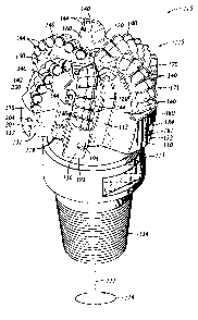
Referring to Figures 3 and 4, an embodiment of a drill bit 110 is a fixed
cutter bit,
sometimes referred to as a drag bit, and is preferably a PD bit adapted for
drilling through
formations of rock to form a borehole. Bit 110 generally includes a bit body
112, a shank 113, and
a threaded connection or pin end 114 for connecting bit 110 to a drill string
(not shown), which is
employed to rotate the bit in order to drill the borehole. Bit 110 and pin end
114 include a bit axis
111 about which bit 110 rotates in the cutting direction represented by arrow
118. Bit body 112
has a bit face 120 that supports a cutting structure 115 and is formed on the
end of bit I10
generally opposite pin end 114. Body 112 may be formed in a conventional
manner using
powdered metal tungsten carbide particles in a binder material to form a hard
metal cast matrix.
Alternatively, the body can be machined from a metal block, such as steel,
rather than being
formed from a matrix.
As best seen in Figure 4, body 112 includes a central longitudinal bore 117
permitting
drilling fluid to flow from the drill string into bit 110. Body 112 is also
provided with downwardly
extending flow passages 121 having ports or nozzles 122 disposed at their
lowermost ends. The
flow passages 121 are in fluid communication with central bore 117. Together,
passages 121 and
nozzles 122 serve to distribute drilling fluids around cutting structure 115
to flush away formation
cuttings during drilling and to remove heat from bit 110.
Referring now to Figures 3-6, cutting structure 115 is provided on bit face
120 of bit 110.
Cutting structure 115 includes a plurality of blades which extend radially
along bit face 120. In the
embodiment illustrated in Figures 3-6, cutting structure 115 includes six
blades 150, 160, 170, 180,
CA 02590439 2010-05-26
190, 200 that are angularly spaced-apart about bit axis 111. In particular, in
this embodiment,
blades 150, 160, 170, 180, 190 and 200 are uniformly angularly spaced about 60
apart on bit face
120. In other embodiments, one or more of the blades may be non-uniformly
angularly spaced
relative to the bit axis. Although bit 110 is shown as having six blades 150,
160, 170, 180, 190 and
200, in general, bit 110 may comprise any suitable number of blades. As one
example only, bit
110 may comprise eight blades.
In this embodiment, blades 150, 160, 170, 180, 190, 200 are integrally formed
as part of,
and extend from, bit body 112 and bit face 120. Further, blades 150, 160, 170,
180, 190, 200
extend radially outward along bit face 120 and then axially along a portion of
the periphery of bit
110. Blades 150, 160, 170, 180, 190 and 200 are separated by drilling fluid
flow courses 119. As
used herein, the terms "axial" and "axially" generally mean along or parallel
to the bit axis (e.g., bit
axis 111), while the terms "radial" and "radially" generally mean
perpendicular to the bit axis. For
instance, an axial distance refers to a distance measured parallel to the bit
axis, and a radial
distance means a distance measured perpendicular from the bit axis.
Referring still to Figures 3-6, each blade 150, 160, 170, 180, 190, 200
includes a cutter-
supporting surface 142 for mounting a plurality of cutter elements 140. Cutter
elements 140 each
include a cutting face 144 having a cutting edge adapted to engage and remove
formation material.
The cutting edge of one or more cutting faces 144 may be chamfered or beveled
as desired.
Although cutter elements 140 are shown as being arranged in radially extending
rows, cutter
elements 140 may be mounted in other suitable arrangements including, without
limitation, arrays
or organized patterns, randomly, sinusoidal pattern, or combinations thereof.
Further, in other
embodiments, one or more trailing backup rows of cutter elements may be
provided on one or
more of the blades.
11
CA 02590439 2010-05-26
Bit 110 further includes gage pads 151, 161, 171, 181, 191, 201 of
substantially equal axial
length in this embodiment. Gage pads 151, 161, 171, 181, 191, 201 are
generally disposed about
the outer circumference of bit 110 at angularly spaced apart locations.
Specifically, each gage pad
151, 161, 171, 181, 191, 201 intersect and extends from one of the blades 150,
160, 170, 180, 190
and 200, respectively. Gage pads 151, 161, 171, 181, 191, 201 are each
integrally formed as part
of the bit body 112.
Each gage pad 151, 161, 171, 181, 191, 201 includes a radially outer formation
or gage-
facing surface 130 and a generally forward-facing surface 131 which intersect
in an edge 132,
which may be radiused, beveled or otherwise rounded. Each gage-facing surface
130 includes at
least a portion that extends in a direction generally parallel to axis 111. As
used herein, the phrase
"gage-facing surface" refers to the radially outer surface of a gage pad that
generally faces the
formation. It should be appreciated that in some embodiments, portions of one
or more gage-
facing surface 130 may be angled, and thus slant away from the borehole
sidewall. Also, in select
embodiments, one or more forward-facing surface 131 may likewise be angled
relative to bit axis
111 (both as viewed perpendicular to axis 111 or as viewed along axis 111).
Thus, gage-facing
surface 130 need not be perfectly parallel to the formation, but rather, may
be oriented at an acute
angel relative to the formation. Surface 131 is termed "forward-facing" to
distinguish it from gage-
facing surface 130, which generally faces the borehole sidewall. A gage
trimmer 154, 164, 174,
184, 194, 204 is mounted to each gage pad 151, 161, 171, 181, 191, 201,
respectively. In
particular, in this embodiment, one gage trimmer 154, 164, 174, 184, 194, 204
extends from the
gage-facing surface 130 of each gage pad 151, 161, 171, 181, 191, 201,
respectively. However, in
other embodiments, none or more than one gage trimmer may be provided on one
or more of the
gage pads.
12
CA 02590439 2010-05-26
Referring specifically to Figure 4, an exemplary profile of bit 110 is shown
as it would
appear with all blades (e.g., blades 150, 160, 170, 180, 190, 200), all cutter
elements 140, and all
gage trimmers 154, 164, 174, 184, 194, 204 rotated into a single rotated
profile. In rotated profile
view, blades 150, 160, 170, 180, 190, 200 of bit 110 form a combined or
composite blade profile
139 generally defined by cutter-supporting surface 142 of each blade.
Composite blade profile 139
and bit face 120 may generally be divided into three regions conventionally
labeled cone region
124, shoulder region 125, and gage region 126. Each region 124, 125, 126 is
generally concentric
with and centered relative to bit axis 111.
Referring still to Figure 4, cone region 124 comprises the radially innermost
region of bit
110 and composite blade profile, and extends radially from bit axis 111 to
shoulder region 125. In
this embodiment, cone region 124 is generally concave. Radially adjacent cone
region 124 is
shoulder (or the upturned curve) region 125. In this embodiment, shoulder
region 125 is generally
convex. The transition between cone region 124 and shoulder region 125 occurs
at the axially
outermost portion of composite blade profile 139 (lowermost point on bit 110
in Figure 4), which
is typically referred to as the nose or nose region 127. Moving radially
outward from bit axis 111,
next to shoulder region 125 is gage region 126 which extends substantially
parallel to bit axis 111
at the outer radial periphery of composite blade profile 139. In this
embodiment, each gage pad
151, 161, 171, 181, 191, 201 generally extends axially from one of the blades
150, 160, 170, 180,
190, 200, respectively.
In general, the geometry, orientation, and placement of the plurality of
blades on a fixed
cutter bit can be varied relative to each other to enhance the ability of the
bit to drill off-axis. In
some cases, directional drilling capabilities can be enhanced by employing
blades with non-
uniform or non-identical configurations. Bits incorporating such non-uniform
blade designs are
13
CA 02590439 2010-05-26
disclosed in U.S. Patent Nos. 5,937,958 and 6,308,970. As will be explained in
more detail below,
in the embodiments of bit 110 disclosed herein, the radial location and
orientation of gage pads
151, 161, 171, 181, 191, 201 are configured to offer the potential for bit 110
to drill off-axis.
Referring now to Figures 5 and 6, the radially outermost surfaces and edges of
bit 110
circumscribe and define a full bit circumference 133 (also known as a full
gage diameter). In this
embodiment, full bit circumference 133 represents the circle circumscribed by
the cutting edges of
the radially outermost cutter elements 140 and gage trimmers 154, 164, 174,
184, 194, 204. In
addition, gage-facing surfaces 130 of gage pads 151, 161, 171, 181, 191, 201
circumscribe and
define a gage pad diameter or circumference 134.
In this embodiment, pin end 114 and full bit circumference 133 are centered
relative to bit
axis 111. However, gage pad circumference 134 is not centered relative to bit
axis 111. Rather,
gage pad circumference 134 is concentric with, and centered relative to, a
gage pad axis 211 that is
substantially parallel to, but offset from (i.e., not collinear), bit axis
111. In this sense, gage pad
circumference 134 may be described as being offset from full bit circumference
133. In other
words, full bit circumference 133 defining the full gage diameter is not
concentric with gage pad
circumference 134. Gage pad axis 211 may also be referred to herein as an
"offset axis" since it is
generally parallel with, but offset from, bit axis 111.
Referring still to Figures 5 and 6, due to the configuration of full bit
circumference 133 and
gage pad circumference 134, the gage-facing surface 130 of select gage pads
are disposed at full
bit circumference 133, while the gage-facing surface 130 of other gage pads
are radially inward or
recessed relative to full bit circumference 133. For example, gage-facing
surface 130 of gage pad
151 is located substantially at full bit circumference 133, while gage-facing
surface 130 of
14
CA 02590439 2010-05-26
remaining gage pads 161, 171, 181, 191, 201 are radially inward or recessed
from full bit
circumference. In other words, gage-facing surface 130 of gage pads 161, 171,
181, 191, 201 are
not disposed at full bit circumference 133. For purposes of clarity and
explanation, the differences
in the diameters of full bit circumference 133 and gage pad circumference 134
have been
exaggerated in Figures 5 and 6.
The amount or degree of radial offset from full bit circumference 133 of gage-
facing
surface 130 of each gage pad 151, 161, 171, 181, 191, 201 may be described by
offset distances
Do-151, Do-161, Do-171, D0-181, Do-191, Do-201, respectively, measured between
the particular gage-
facing surface 130 and the full bit circumference 133 generally perpendicular
to the particular
gage-facing surface 130. Thus, as used herein, the phrase "offset distance"
may be used to refer to
the distance between a gage-facing surface of a gage pad and the full bit
circumference as
measured perpendicular to the gage-facing surface. It should be appreciated
that the radial offset
distance of a particular gage-facing surface (e.g., gage-facing surface 130)
may not be constant
along its entire circumferential length. Thus, as used herein, the "offset
distance" of a gage-facing
surface refers to the maximum offset distance for the particular gage-facing
surface relative to the
full bit circumference. Still further, it should be appreciated that a gage-
facing surface (e.g., gage-
facing surface 130) disposed substantially at the full bit circumference
(e.g., full bit circumference
133) has an offset distance of zero.
Referring still to Figure 5 and 6, gage-facing surface 130 of gage pad 181 has
the greatest
offset distance Do-181. In other words, offset distance Do-181 of gage pad 181
is greater than offset
distances Do-151, Do-161, Do-171, Do-191, Do-201 of remaining gage pads 151,
161, 171, 191, 201,
respectively. In addition, gage-facing surface 130 of gage pad 151 has an
offset distance Do.151 that
is less than offset distances Do-161, Do-1n, Do-181, Do-191, Do-201 of
remaining gage pads 161, 171,
CA 02590439 2010-05-26
181, 191, 201, respectively. In particular, gage-facing surface 130 of gage
pad 151 is disposed
substantially at full bit circumference 133, and thus, has a radial offset
distance Do-151 of zero.
Offset distances Do-171, Do-191 are each greater than offset distances Do-161,
Do-201. The offset
distance Do-151, Do-161, Do-171, Do-181, Do-191, Do-201 of each gage pad 151,
161, 171, 181, 191, 201,
respectively, may be varied depending on a variety of factors including,
without limitation, the
application, the bit size, the desired side cutting capability, or
combinations thereof. Each offset
distance Do-151, Do-161, Do-n1, Do-131, Do-191, Do-201 is preferably between
zero and 0.20 in.
Although certain gage-facing surfaces 130 do not extend to full bit
circumference 133, the
radially outermost cutting edge of each gage trimmer 154, 164, 174, 184, 194,
204 does extend
from its respective gage pad 151, 161, 171, 181, 191, 201, respectively, to
full bit circumference
133. In other words, the outermost cutting tips of each gage trimmer 154, 164,
174, 184, 194, 204
circumscribes full bit circumference 133 even though the formation-facing
surface 130 from which
it extends is offset from full bit circumference 133. Consequently, the
distance that each gage
trimmer 154, 164, 174, 184, 194, 204 extends from its gage pad 151, 161, 171,
181, 191, 201,
respectively, will depend on the position of gage facing surface 130 to which
it is mounted. For
example, formation-facing surfaces 130 of blades 170, 180 are disposed further
from full bit
circumference 133 than formation-facing surfaces 130 of blades 150 and 160.
Consequently, gage
trimmers 174, 184 associated with blades 170, 180, respectively, extend
farther from their
respective gage-facing surface 130 than gage trimmers 154, 164 associated with
blades 150, 160,
respectively.
In general, each gage-trimmer (e.g., gage-trimmer 154, 164, 174, 184, 194,
204) extends
from its gage pad (e.g., gage pad 151, 161, 171, 181, 191, 201) to an
extension height measured
perpendicularly from the gage-facing surface to the outermost point of the
gage-trimmer. As
16
CA 02590439 2010-05-26
previously described, in this embodiment, each gage-trimmer 154, 164, 174,
184, 194, 204 extends
from gage-facing surface 130 of gage pads 151, 161, 171, 181, 191, 201,
respectively, to full bit
circumference 133. Thus, in this embodiment, the extension height of each gage-
trimmer 154,
164, 174, 184, 194, 204 is substantially the same as the offset distance
Do_151, Do-161, Do-171, Do-181,
Do-191, Do-201, respectively.
The differences in the extension heights of gage trimmers 154, 164, 174, 184,
194, 204
impact their ability to penetrate or shear the formation during drilling
operations. In general, the
greater the extension height of a cutter element or gage trimmer, the greater
the potential depth of
penetration of the cutter element or gage trimmer into the formation. For
instance, gage trimmer
gage trimmer 174 of blade 170 has a greater extension height than gage-trimmer
204 of blade 200,
and thus, has the potential to penetrate deeper into the formation than gage-
trimmer 204 before
gage pad 201, 171, respectively, contact the formation. In general, once a
gage-trimmer has
penetrated the formation to a depth substantially equal to its extension
height, the gage pad to
which it is mounted will begin to contact, slide, and scrape across the
formation, thereby reducing
the ability of the gage trimmer to further penetrate or shear the earthen
formation. Without being
limited by this or any particular theory, such reduction in the gage-trimmers
ability to further
penetrate the formation results because the forces exerted on the formation
become distributed over
the entire surface area of gage-facing surface (e.g., gage-facing surface 130)
of the gage pad (e.g.,
gage pad 151) rather than being purely concentrated at the tips of the gage
trimmer. Consequently,
the force per unit area exerted on the formation is reduced, thereby reducing
the ability of the gage
trimmer to penetrate or shear the formation material. Thus, gage trimmers with
greater extension
heights tend to penetrate further into the formation, and hence shear the
formation more
effectively, as compared to gage trimmers with smaller extension heights.
17
CA 02590439 2010-05-26
In the embodiment shown in Figures 5 and 6, gage trimmer 184 has the greatest
extension
height, followed by gage-trimmers 174, 194, which in turn, have greater
extension heights than
gage-trimmers 164, 204. As previously described, gage-facing surface 130 of
gage pad 151 is
disposed substantially at full gage circumference, and thus, gage-trimmer 154
has the an extension
height of about zero - the smallest extension height of any of gage-trimmer.
In this manner, embodiments of bit 110 include gage trimmers 154, 164, 174,
184, 194,
204 having different extension heights and different formation penetrating
capabilities. In general,
the greater the extension height of the gage trimmer, the greater its
formation engaging and cutting
ability. Thus, by selectively controlling the extension height of gage
trimmers 154, 164, 174, 184,
194, 204, the formation penetrating ability and cutting effectiveness of each
gage trimmer 154,
164, 174, 184, 194, 204 may be varied and controlled.
Referring briefly to Figure 2, as previously described, when drill bit 51
deviates a small
angle from vertical, weight vector 52 of drill string 53 acting on drill bit
51 includes an axial
component 54 generally aligned with the bit axis, and a normal or radial
component 56 generally
perpendicular to bit axis. Axial component 54 urges drill bit 51 further into
the formation
generally along the direction of the bit axis, however, radial component 56
urges the drill string
into the borehole sidewall 57 generally towards a vertical orientation. In
this sense, normal or
radial component 56 may also be described as a restoring force, since it urges
drill bit 51 back
towards a vertical orientation.
Without being limited by this or any particular theory, for a drill bit
without gage cutter
relief (e.g., a drill bit without gage-trimmers extending from the gage-facing
surface), the radial,
restoring forces urging the drill bit back to the vertical orientation may not
be sufficient to activate
18
CA 02590439 2010-05-26
side cutting of the borehole sidewall and allow the bit to return to the
vertical drilling direction.
Instead, such restoring forces will be distributed across the relatively large
surface area of the gage-
facing surfaces, thereby reducing the force per unit area acting on the
borehole sidewall. However,
embodiments described herein (e.g., embodiments of bit 110) include gage
trimmers (e.g., gage
trimmers 164, 174, 184, 194, 204) that extend from their respective gage pad
(e.g., gage pads 161,
171, 181, 191, 201). In such embodiments, the radial, restoring forces, acting
on the bit are, at
least initially, concentrated at the tips of the gage-trimmers, each having a
relatively small surface
area. The force per unit area exerted on the formation by such gage-trimmers
may exceed the
formation strength, and thus, begin to shear the borehole sidewall and
activate side cutting in the
direction of the radial, restoring force. Consequently, embodiments of bit 110
offer the potential
for drilling and formation penetration in a direction that is not parallel
with the longitudinal axis
111 of bit 110. More specifically, embodiments of bit 110 offer the potential
for a drill bit that
tends to return to a vertical upon deviation therefrom. It should also be
appreciated that in addition
to the weight vector of the drill string acting on the drill bit, a bending
moment in the drill string
may also urge the drill bit into the lower side of the borehole in the
direction of zero deviation from
vertical.
The nature of a PDC cutting structure layout (e.g., blades and cutter
elements) typically
results in an asymmetric distribution of forces about the bit. In some cases,
such asymmetric
forces can lead to force imbalances that may result in bit vibrations, or
possibly bit whirl. As
previously described, vibrations and bit whirl can lead to unpredictable, and
potentially damaging,
forces acting on the cutter elements and gage-trimmers, particularly, during
side cutting and
directional drilling operations. However, asymmetric gage pad circumference
134 and non-
uniform extension heights of gage trimmers 154, 164, 174, 184, 194, 204 of bit
110 offer the
19
CA 02590439 2010-05-26
potential to resist vibration and whirl. More specifically, the positioning
and orientation of each
gage-facing surface 130 and each gage trimmers 154, 164, 174, 184, 194, 204
may be selected to
control the loading of each gage-trimmer 154, 164, 174, 184, 194, 204. In
particular, the
circumferential position and radial position of each gage-facing surface 130
(i.e., offset distances
Do-151, Do-161, Do-171, D0-181, Do-191, Do-201), as well as the extension
height of each gage-trimmer
154, 164, 174, 184, 194, 204 may be designed and configured to minimize the
imbalance forces
generated by cutting structure 115. For instance, in an embodiment, the
circumferential position of
each gage pad 151, 161, 171, 181, 191, 201 relative to full gage circumference
133, the offset
distances Do-151, Do-161, Do-171, Do-181, D0-191, Do-201 of each gage-facing
surface 130, and the
extension heights 154, 164, 174, 184, 194, 204 of each gage-trimmer 154, 164,
174, 184, 194, 204
may be selected to counteract the anticipated imbalance forces generated by
cutting structure 115.
Such a bit with minimized net unbalanced forces offers the potential for
reduced vibrations and
whirl, and hence, more durability. In another embodiment, the circumferential
position of each
gage pad 151, 161, 171, 181, 191, 201 relative to full gage circumference 133,
the offset distances
D0-151, D0-161, D0-171, D0-181, D0-191, Do-201 of each gage-facing surface
130, and the extension heights
154, 164, 174, 184, 194, 204 of each gage-trimmer 154, 164, 174, 184, 194, 204
may be selected to
enhance side cutting tendencies of cutting structure 115.
Various techniques may be employed to manufacture the embodiment of Figures 5
and 6.
For example, bit 110 can be cast so that gage pads 151, 161, 171, 181, 191,
201 extend to full bit
circumference 133 and are then selectively recessed from full bit
circumference 133 by grinding or
machining. Alternatively, bit 110 can be cast such that gage pads 151, 161,
171, 181, 191, 201 are
recessed from full bit circumference 133 without subsequent manufacturing
processes.
CA 02590439 2010-05-26
While specific embodiments have been shown and described, modifications
thereof can be
made by one skilled in the art without departing from the scope or teaching
herein. The
embodiments described herein are exemplary only and are not limiting. For
example,
embodiments described herein may be applied to any bit layout including,
without limitation, single
set bit designs where each cutter element has unique radial position along the
rotated cutting profile,
plural set bit designs where each cutter element has a redundant cutter
element in the same radial
position provided on a different blade when viewed in rotated profile, forward
spiral bit designs,
reverse spiral bit designs, or combinations thereof. In addition, embodiments
described herein may
also be applied to straight blade configurations or helix blade
configurations. Many other variations
and modifications of the system and apparatus are possible. For instance, in
the embodiments
described herein, a variety of features including, without limitation, the
number of blades (e.g.,
primary blades, secondary blades, etc.), the spacing between cutter elements,
cutter element
geometry and orientation (e.g., backrake, siderake, etc.), cutter element
locations, cutter element
extension heights, cutter element material properties, or combinations thereof
may be varied among
one or more primary cutter elements and/or one or more backup cutter elements.
Accordingly, the
scope of protection is not limited to the embodiments described herein, but is
only limited by the
claims that follow, the scope of which shall include all equivalents of the
subject matter of the
claims.
21