Note: Descriptions are shown in the official language in which they were submitted.
CA 02590455 2009-03-27
REMOTE BATTERY COMPARTMENT FOR CHILD SWING MOTOR
The present invention relates generally to a motor driven infant swing
and, more particularly, to a remote battery compartment supported on the swing
frame to locate the batteries away from an infant positioned on the swing sea.
BACKGROUND OF THE INVENTION
Baby swings are used extensively by infant caregivers to soothe and to
comfort the children. An infant swing consists primarily of a seat that
securely holds
the infant in a position elevated off the floor and a frame apparatus that
supports the
seat and allows the seat to move in a reciprocal manner, typically in a
forward and
rearward direction though some infant seats provide a side to side swinging
motion.
The first infant swings consisted of a seat suspended from a frame that
was formed with a support structure that extended over top of the infant and
was
supported by transversely opposed support legs that hold the overhead support
structure in the elevated position. This overhead support structure restricted
access
to the child positioned in the seat as the support structure presented a
physical
barrier directly above the child. Such an infant swing can be seen in U. S.
Design
Patent No. D345,777, issued on April 4, 1994, to Daniel Pinch, et al. Not only
is the
overhead support structure a barrier to accessing the child in the swing from
above
the child, but the support structure also presented a barrier to viewing the
infant.
As a solution to the barrier presented by the overhead support
structure, the "open top" infant swing was developed. As can be seen in U. S.
Patent No. 4,822,033, issued to Louis Kohus and James Mariol on April 18,
1989,
CA 02590455 2009-03-27
2
the overhead structural support has been eliminated to provide an open access
to
the child in the seat from above. However, the child can be capable of
grasping
either of the transversely opposing support legs, particularly as the child is
swinging
back and forth between the support legs. Contact between the swinging child
and
one of the support legs can result in injury to the child. Furthermore, the
child can
potentially grab one of the support legs and pull his or herself forwardly to
become
dislodged from the seat, particularly if the child has not been properly
secured within
the seat by a safety harness.
The aforementioned open top infant swing evolved in a manner to
eliminate the frame structure, i.e. the support legs, positioned forwardly of
the
swinging seat to provide an "open side" swing frame configuration for an
infant
swing. Such an open side infant swing can be found in the aforementioned U. S.
Patent No. 4,822,033, issued to Kohus and Mariol on April 18, 1989. In the
Kohus
and Mariol patent, the infant swing is provided with both an open top and an
open
side structural configuration to provide the capability of viewing and
accessing the
child within the seat from substantially any position forwardly of the seat.
The swinging motion of most baby swings commercially available is
similar to that of a pendulum that pivots from above and to the sides of the
seat.
Although this swinging motion can be maintained by a mechanical spring-
operated
swing mechanism, the swinging motion in most modern infant swings is
maintained,
typically, by a small electric motor located adjacent one of the seat pivots
supported
by the frame structure. The power for this electric motor is typically an
array of dry
CA 02590455 2009-03-27
3
cell batteries located within the same plastic housing as the electric motor.
Examples of battery operated motors to affect the swinging motion of the
infant setlt
from a frame support can be seen in U. S. Patent No. 5,525,113, issued to
Daniel
Mitchell, et al on June 11, 1996, and in U. S. Patent No. 5,833,545, issued to
Daniel
Pinch, et al on November 10, 1998.
Although such an arrangement of placing the dry cell batteries within
the same covered housing as the electric motor is convenient for the wiring of
the
power source to the electric motor, this arrangement has several disadvantages
as
well. Locating the placement of the dry cell batteries above the swing seat,
exposes
the child positioned within the seat to being impacted by a dropped battery
when the
caregiver is forced to change the batteries to replace depleted batteries with
fresh
ones. Dry cell batteries are manufactured with acid within the battery
container.
Sometimes that acid can escape from the battery which would also present an
injury
risk to a child positioned within the seat. The placement of the battery array
within
the same housing as the electric motor also increases the height of the center
of
gravity of the swing, thus increasing the possibility of the swing tipping
over. Lastly,
since the spatial requirements of an electric motor and battery array are
greater than
for just the electric motor alone, the size of the housing needed to contain
the
electric motor and the battery array detracts from the ability to view the
child.
SUMMARY OF THE INVENTION
CA 02590455 2009-03-27
4
According to a first aspect of the invention there is provided, in a child
swing having a seat assembly mounted for reciprocal movement, said seat
assembly having a top surface, the improvement comprising:
a pair of transversely spaced rear legs projecting upwardly and
forwardly from a rear support position and terminating at respective elevated
distal
ends;
a pair of transversely spaced front legs extending upwardly and
rearwardly from a front support position, said front legs intersecting the
corresponding said rear legs at a central region of said rear legs;
a mounting housing mounted on each said rear leg at said central
region to receive the corresponding said front leg for support thereof;
a hanger housing mounted on the distal end of each said rear leg for
support of said seat assembly for reciprocal movement thereof in a direction
'bf
movement;
an electric motor supported in one of said hanger housings and being
operably connected to said seat assembly to power said reciprocal movement
thereof; and
a battery compartment supported in one of said mounting housings
located vertically below said top surface of said seat assembly and remotely
of said
electric motor to retain an array of batteries to provide electrical power to
said
electric motor.
CA 02590455 2009-03-27
Preferably said electric motor and said battery compartment are
mounted on the same rear leg.
Preferably said battery compartment includes electrical contacts for
engaging each said battery, said electrical contacts being connected to said
electric
5 motor by wiring located internally of said rear leg interconnecting said
battery
compartment and said electric motor.
Preferably said battery compartment includes a removable cover to
permit access to said array of batteries.
Preferably said front and rear legs are curved to provide an open side
access to said seat assembly.
Preferably said curved front and rear legs position said mounting
housings rearwardly of said seat assembly and rearwardly of said hanger
housings.
According to a second aspect of the invention there is provided, in a
child swing having a seat assembly mounted for reciprocal movement in a fore-
and-
aft direction on a frame assembly, an electric motor operably connected to
said seat
assembly to power said reciprocal movement, and a battery array electrically
coupled by wiring to said electric motor to provide electrical power for the
operation
of said electric motor, the improvement comprising:
a pair of transversely spaced rear legs projecting upwardly and
forwardly from a rear support position and terminating at respective elevated
distal
ends;
CA 02590455 2009-03-27
6
a pair of transversely spaced front legs extending upwardly and
rearwardly from a front support position, said front legs intersecting the
corresponding said rear legs at a central region of said rear legs;
a mounting housing mounted on each said rear leg at said central
region to receive the corresponding said front leg for support thereof;
a hanger housing mounted on the distal end of each said rear leg for
support of said seat assembly for reciprocal movement thereof in a direction
of
movement; and
said array of batteries being located in a battery compartment
supported on said frame assembly remotely from said electric motor.
Preferably said electric motor is supported within one of said hanger
housings, said battery compartment being supported within one of said mounting
housings.
Preferably said electric motor and said battery compartment are
supported on a common one of the rear legs.
Preferably said battery compartment includes eiectrical contacts for
engaging said batteries within said array of batteries, said electrical
contacts being
connected to said electric motor by wiring passing internally through said
common
one of the rear legs and said one of said mounting housings which supports
said
battery compartment.
Preferably said seat assembly has a top surface, said battery
compartment being located vertically below said top surface of said seat
assembly.
CA 02590455 2009-03-27
7
Preferably said battery compartment is located rearwardly of said seat
assembly and rearwardly of said hanger housings.
According to a third aspect of the invention there is provided a child
swing comprising:
a pair of transversely spaced rear legs projecting upwardly and
forwardly from rear support positions and terminating at respective elevated
distal
ends;
a pair of transversely spaced front legs extending upwardly and
rearwardly from front support positions, said front legs intersecting the
corresponding said rear legs at a central region of said rear legs;
a mounting housing mounted on each said rear leg at said central
region to detachably receive the corresponding said front leg for support
thereof
such that said distal ends of said rear legs are cantilevered from said
mounting
housing;
a hanger housing mounted on said distal end of each said rear leg for
support of a seat assembly for reciprocal movement thereof in a direction of
movement;
said seat assembly including a seat member and a pair of opposing
hangers interconnecting said seat member and respective said hanger housings,
said front and rear legs providing an unrestricted access to said seat
assembly from
a side direction of said seat assembly, said cantilevered distal ends of said
rear legs
CA 02590455 2009-03-27
8
providing an unrestricted access to said seat assembly from above said seat
assembly;
an electric motor supported in one of said hanger housings and being
operably connected to said seat assembly to power said reciprocal movement
thereof; and
a battery compartment supported in one of said mounting housings to
retain an array of batteries to provide electrical power to said electric
motor.
Preferably said electric motor and said battery compartment are
supported on a common one of the rear legs.
Preferably said battery compartment includes electrical contacts for
engaging said batteries within said array of batteries, said electrical
contacts being
connected to said electric motor by wiring passing internally through said
common
one of the rear legs and said mounting housing.
Preferably said seat assembly has a top surface, said battery
compartment being located vertically below said top surface of said seat
assembly.
Preferably said battery compartment is located rearwardly of said seat
assembly and rearwardly of said hanger housings.
The arrangement described in detail hereinafter may provide one or
more of the following features and advantages:
to provide a child swing that is powered by an electric motor having the
battery power supply positioned at a location remote from the location of the
electric
motor.
CA 02590455 2009-03-27
9
to provide a frame for an infant swing that overcomes the
aforementioned disadvantages of the prior art.
that the swing frame apparatus provides a substantially unrestricted
view of a child seated within the seat of the infant swing from positions
forwardly of
the infant swing.
that the swing frame apparatus provides a substantially unrestricted
physical access to a child seated within the seat of an infant swing from
above and
forwardly of the seat.
that the swing frame provides an open top and open side configuration
for an infant swing.
to provide a frame apparatus for an infant seat in which the front legs
are joined with curved rear legs at a mid-portion thereof to permit said rear
legs to
project upwardly and forwardly therefrom.
that the curved rear legs terminate at hanger housings from which the
infant seat can be suspended.
that the hanger housings are supported in a cantilevered manner from
the support provided by the joinder of the front legs with the rear legs at a
mid-
portion of the rear legs.
that the front legs can be detached from the rear legs to permit a
compact storage of the swing frame apparatus with the seat structure removed
from
the frame apparatus.
CA 02590455 2009-03-27
that the joinder of the front legs with the mid-portion of the rear legs is
accomplished through a mounting housing supported on each rear leg for the
detachable connection of a corresponding front leg.
that the front leg is connected to the mounting housing through a quick
5 disconnect mechanism.
to utilize the mounting housing located below the motor housing to
support the array of dry cell batteries to provide a power source for the
electric motor
providing the swinging motion for the infant seat.
that the dry cell battery array is located below the level of a child
10 seated within the infant seat.
that the location and the height of the dry cell battery array do not
expose a child located within the swing seat to danger from acid leaking from
the
bafteries located in the array,
that the location and the height of the dry cell battery array providing
power to the electric swing motor do not expose a child within the swing seat
to
danger from a battery falling from the storage compartment housing the dry
cell
battery array.
that the housing encompassing the electric motor for an infant swing
can be formed in a smaller configuration by removing the dry cell battery
array into a
mounting housing located at a remote location with respect to the housing for
the
electric motor.
CA 02590455 2009-03-27
11
that the smaller housing for the electric motor on a child's swing
enhances the ability to view the child in the swing seat.
to provide a structural component for an infant swing frame that is
formed in a non-circular cross-section with a cross sectional dimension that
is
greater in an axis parallel to the direction of movement of a swinging infant
seat than
in an axis perpendicular to the direction of movement.
that the cross sectional configuration of the swing frame member is in
an oval shape.
that the swing frame having oval-shaped frame members is stronger in
resisting the swinging movement of the infant seat than a swing frame formed
with
frame members having a circular cross sectional shape.
to provide a frame apparatus for a child's swing that is aesthetically
pleasing while establishing an open top and open side configuration for access
to
and viewing of the swing seat.
that the swing frame apparatus utilizes a pair of transversely spaced
curved rear legs that are oriented in an upwardly and forwardly reaching
configuration with corresponding curved front legs that are oriented upwardly
and
rearwardly to intersect the rear legs at mounting housings to permit
connection of
the front legs to the rear legs at a mid-portion thereof.
that the opposing front legs are joined at the lowermost forward
aspects thereof by a molded front cross brace.
CA 02590455 2009-03-27
12
to provide a remote battery compartment for the electric motor
powering the movement of a child's swing, which is durable in construction,
inexpensive of manufacture, carefree of maintenance, facile in assemblage, and
simple and effective in use.
BRIEF DESCRIPTION OF THE DRAWINGS
The advantages of this invention will be apparent upon consideration
of the following detailed disclosure of the invention, especially when taken
in
conjunction with the accompanying drawings wherein:
Figure 1 is a front elevational view of an infant swing having a frame
apparatus incorporating the principles of the instant invention.
Figure 2 is a top plan view of the infant swing depicted in Figure 1.
Figure 3 is a right side elevational view of the infant swing shown in
Figures 1 and 2.
Figure 4 is a left side elevational view of the infant swing shown in
Figures 1 and 2.
Figure 5 is. a left, front perspective view of the infant swing shown in
Figures 1 and 2.
Figure 6 is an exploded view of the major components of the infant
swing disassembled to convert the infant swing into a more compact transport
or
storage configuration.
CA 02590455 2009-03-27
13
Figure 7 is an enlarged exploded view of the battery case formed with
one of the mounting housings at the junction of the corresponding front and
rear legs
of the frame apparatus.
Figure 8 is an enlarged cross sectional view of a frame member taken
along lines 8-8 of Figure 7 to depict the oval-shaped cross sectional
configuration of
the frame member.
DETAILED DESCRIPTION OF THE PREFERRED EMBODIMENT
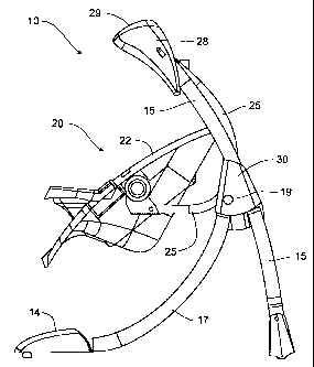
Referring now to the drawings, an infant swing having a frame
apparatus incorporating the principles of the instant invention can best be
seen. The
infant swing 10, as can best be seen in Figure 6, includes as the major
components
thereof a frame assembly 12, including a pair of transversely spaced rear legs
15
and a corresponding pair of front legs 17, and a seat assembly 20 suspended
from
the frame assembly 12 for a fore-and-aft swinging movement. The seat assembly
is formed of a molded seat member 22 and a pair of transversely spaced hangers
15 25 that are connected to corresponding hanger housings 27, 28 positioned at
the
cantilevered ends of the rear legs 15, as will be described in greater detail
below.
Referring now to Figures 1 - 6, the frame assembly 12 is formed with a
pair of transversely opposing rear legs 15 that extend upwardly and forwardly
front a
rearward support position with a curvature thereof being concave facing
downwardly
20 and forwardly. The rear legs 15 terminate at upper hanger housings 27, 28
at the
elevated distal ends thereof. One of the hanger housings 28 is formed to
encompass an electric motor 29 that is operable to move the seat assembly 20
in a
CA 02590455 2009-03-27
14
reciprocal manner in a fore-and-aft direction, as will be described in greater
detail
below. The curvature of the rear legs 15 provide an aesthetically pleasing
shape
that positions the hanger housings 27, 28 at an elevated, cantilevered
position with
no structure immediately below the hanger housings 27, 28.
A corresponding pair of curved front legs 17 is positioned forwardly of
the rear legs 15 in fore-and-aft alignment therewith to extend rearwardly and
upwardly from a front support position to intersect with the corresponding
rear legs
17 at a central point thereof. Each of the rear legs 15 has mounted thereon at
the
central point thereof a mounting housing 18, 30 for the connection of the
corresponding front leg 17 by a quick connect mechanism 19 that enables the
front
legs 17 to be detachably connected to the rear legs 17 and removed therefrom
to
convert the swing 10 into a storage configuration without the use of tools,
such as a
screwdriver or a wrench. The curvature of the front legs 17 is concave
upwardly and
forwardly so that the front legs 17 also do not provide any substantial
structure
beneath the hanger housing s 27, 28. The mating curvatures of the rear legs 15
and
the front legs 17 establish an open side configuration of the frame assembly
12 with
respect to access to a seat assembly 20 hanging from the hanger housings 27,
28.
The front legs 17 are interconnected by a molded front cross brace 14
that preferabiy has a curved configuration to correlate with the curved front
and rear
legs 17, 15 and provide an aesthetically pleasing appearance. Similarly, the
transversely opposing rear legs 15 are also interconnected by a rear cross
brace
member 13 to provide a stable support for the suspended seat assembly 20 to
resist
CA 02590455 2009-03-27
the forces associated with the fore-and-aft swinging of an infant positioned
in the
seat assembly 20. The curvature of the molded front cross brace 14 eliminates
the
conventional tubular structural member that is positioned between the front
legs.
The rearwardly curved shape enables the caregiver to approach the seat
assembly
5 20 for insertion or removal of the child from the seat member 22 without
interfering
with or tripping over the front cross brace found on conventional infant
swings.
The seat assembly 20 includes a molded seat member 22 that
is more particularly described in commonly owned US Patent 7,507,163 issued
March 24th 2009 by inventor Robert E. Haut.
10 The seat member 22 provides a support structure in which an infant
can be placed and secured within the seat member 22 by conventional safety
restraints (not shown) and permitted to reciprocally swing in a fore-and-aft
direction.
The seat member 22 is supported from the hanger housings 27, 28 by curved
hangers 25 that connect with the seat member 22 and present a concave shape in
a
15 forward direction. As a result, the curvature of the hangers 25 contributes
to the
structure-free configuration beneath the hanger housings 27, 28, in addition
to the
mating curvatures of the front and rear legs 17, 15, to establish the open
side
configuration for access to the seat member 22.
As is best seen in Figure 8, the structural members forming the front
and rear legs 17, 15 are formed from an oval-shaped tubular member that
provides
a longer dimension in a direction parallel with the swinging movement of the
seat
assembly 12, depicted by the arrow 38, than in the direction perpendicular to
the
CA 02590455 2009-03-27
16
swinging movement of the seat assembly 12, represented by arrow 39. This oval-
shaped cross sectional configuration of the structural frame members provides
a
frame that is stronger in the resistance of the swinging motion than a frame
having
the same amount of material but formed in a conventional round cross sectional
configuration.
The transversely spaced hanger housings 27, 28 without any structural
member interconnecting the upper distal ends of the rear legs 17 provides an
open
top configuration for the frame assembly 12, while the curved rear and front
legs 15,
17, along with the curved hangers 25, provide an open side configuration for
the
frame assembiy 12. Accordingly, the caregiver can access the child positioned
in
the seat member 22 from above, from in front, or from the side of the seat
assembly
without interference from the frame assembly 12. These mating, curved shapes
forming the frame assembly 12 establish an improved access, physically and
visually, to the seat assembly 20 and any child positioned therein.
15 The mounting housing 30 mounted on the rear leg 17 on which the
hanger housing 28 and the electric motor 29 are found is used to house an
array of
dry cell batteries 32 to provide power for operation of the electric motor 29.
The
placement of the battery array 32 at the connection of the front leg 17 with
the
curved rear leg 15 keeps the battery array 32 below the level of the head of
the child
20 positioned within the seat member 22, thus protecting the infant from
possible injury
from damaged batteries or from batteries that may be dropped onto the child
seated
in the seat member 22. The placement of the batteries 32 in the mounting
housing
CA 02590455 2009-03-27
17
30 also enables the size of the hanger housing 28 in which the electric motor
29
resides to be smaller than if the batteries 32 were placed in the hanger
housing 30
with the electric motor 29. Such geometry allows the two hanger housings 27,
28 to
be sized similarly to provide an aesthetically pleasing frame structure.
The batteries 32 are mounted within individual compartments 33
having contacts 35, 36 arranged in series to provide electrical power for
operating
the electric motor 29 through wiring 37 that passes internally of the rear leg
15 to
connect with the electric motor 29. A removable ccver 31 retains the
individual
batteries 32 in their respective compartments 33 until replacement is
required.
It will be understood that changes in the details, materials, steps and
arrangements of parts which have been described and illustrated to explain the
nature of the invention will occur to and may be made by those skilled in the
art upon
a reading of this disclosure within the principles and scope of the invention.
The
foregoing description illustrates the preferred embodiment of the invention;
however,
concepts, as based upon the description, may be employed in other embodiments
without departing from the scope of the invention.