Note: Descriptions are shown in the official language in which they were submitted.
CA 02590488 2009-05-13
- 1 -
Construction device, in particular a drillinq device
Field of the Invention
The invention relates to a construction device, in particular a
drilling device. Such a construction device comprises a carrier
vehicle having an undercarriage, a mast element arranged at the
front side of the carrier vehicle and a winch drum which is
supported in a rotatable manrner on the carrier vehicle.
Background of the Invention
A construction device of such type is known for example from DE
103 43 079 B3, published May 19, 2005. The known construction
device has a carrier vehicle with a mast, on which a drilling
device having a drill rod is supported in a longitudinally
movable manner. The drill rod is carried by a rope, which can be
actuated by means of a main winch arranged on the rooftop of the
carrier vehicle.
Summary of the Invention
The object of the invention is to provide a construction device
of high stability whose transport dimensions are particularly
small.
The object is solved in_accordance with the invention by a
construction device having a carrier vehicle having an
undercarriage, a mast element arranged at the front side of the
carrier vehicle, and a winch drum which is supported in a
rotatable manner on the carrier vehicle. Preferred embodiments
are stated in the dependent claims.
The construction device according to the invention is
characterized in that the winch drum is arranged in an adjustable
manner on the carrier vehicle between a first position, in which
it is arranged on the upper side of the carrier vehicle, and a
second position, in which it is arranged in a rear portion of the
carrier vehicle.
CA 02590488 2007-05-29
- 2 -
A fundamental idea of the invention can be seen in the fact
that the winch drum is provided on the carrier vehicle not
only in a rotatable manner but also in a movable manner
together with its axis of rotation relative to the carrier
vehicle. For the operation of the construction device the
winch drum is suitably arranged in the first position on the
upper side of the carrier vehicle. In this position it is
located comparatively close to the front side of the carrier
vehicle and hence to the mast element. As a result, a rope
element located on the mast element can be taken up by the
winch drum in a particularly easy way without requiring any
complicated deflection devices. For the transport of the
construction device provision is made according to the
invention for the winch drum to be moved into the second
position in the rear portion of the carrier vehicle. Compared
to the arrangement on the upper side of the carrier vehicle
the vertical clearance of the carrier vehicle determined by
the winch drum is reduced in the rearward arrangement,
whereby a particularly low transport height of the
construction device is achieved.
In addition, by the translational movement, in accordance
with the invention, of the winch drum relative to the carrier
vehicle the centre of mass of the carrier vehicle can be
influenced selectively and therefore an especially high
stability can be achieved.
According to a preferred embodiment of the invention a
construction device having a particularly simple design is
provided in that the winch drum is supported in a winch
frame, wr.ich is supported in a pivotable manner about a
horizontal pivot axis. The horizontal pivot axis is suitably
provided in a corner portion on the carrier vehicle. By
preference, this corner portion is located on the transition
between an approximately vertically extending rear part and
CA 02590488 2007-05-29
- 3 -
an approximately horizontally extending roof part of the
carrier vehicle. In arranging the pivot axis in the corner
portion it is possible to pivot the winch drum together with
the winch frame in a simple manner about the corner portion
between the two positions.
To permit particularly easy transport of the construction
device it is of advantage that the mast element is pivotably
supported on the carrier vehicle between a substantially
vertical operating position and a substantially horizontal
transport position. In principle, provision can also be made
for the mast element to be removed at least partly for the
transport of the carrier vehicle.
According to the invention provision can be made for the mast
element to be folded forwardstowards the front side in the
transport position. In such an embodiment the displacement of
the centre of mass towards the front side resulting from the
folding of the mast element into the transport position can
be compensated at least partly in that, according to the
invention, the winch drum is moved into the second, rearward
position.
Alternatively, provision can be made for the mast element to
be folded backwards over the carrier vehicle in the transport
position. By moving the winch drum from the first rooftop
position into the second position the pivot angle of the mast
element can be increased in this embodiment and consequently
the vertical clearance can be reduced.
Furthermore, in accordance with tr'ie invention it is
advantageous for the pivot axis of the winch frame to extend
at least approximately parallel to a pivot axis of the mast
element.
CA 02590488 2007-05-29
- 4 -
In addition, it is useful that at least one linear drive, in
particular a hydraulic cylinder is provided for adjustment of
the winch drum. For best suitability the linear drive is
arranged on the one hand on the winch frame and on the other
hand preferably on the carrier vehicle.
It is especially advantageous for the linear drive to be
arranged on an actuating mechanism for pivoting the mast
element. In this case the linear drive can preferably serve
both for the pivoting of the mast element and for the
movement of the winch drum. For best suitability the mast
element and the winch drum are adjusted simultaneously at
least at times.
According to the invention a particularly reliable
construction device is attained in that a detachable fixing
device is provided for fixing the winch drum in the first
position. For instance the fixing device can have lugs
arranged on the winch frame and in a corresponding fashion on
the carrier vehicle, in which case a bolt can be inserted
through the lugs in order to fix the winch drum.
The work involved for the transport of the construction
device according to the invention, whilst ensuring
particularly good stability, can be reduced further in that
at least one counterweight is detachably arranged on the rear
of the carrier vehicle in a receiving portion for the winch
drum in the second position. During operation of the
construction device, when the winch drum is located in the
first position outside the receiving portion, the
counterweight can be installed in the receiving portion so as
to increase the tilt resistance. For the transport of the
carrier vehicle, especially when the mast element is in an
inclined position or removed, the counterweight can be
removed. Through this the receiving portion is cleared and
CA 02590488 2009-05-13
- 5 -
the winch drum can be placed into the second position. In this
position the winch drum assumes with its proper weight at least
partly the function of the counterweight, and due to the absence
of the counterweight the total weight of the construction device
is reduced for easy transport.
In particular, the winch drum can be provided for winding up a
rope element, e.g. a supporting rope, that extends at least in
sections on the mast element. The winch drum may also serve to
wind up e.g. other elongated materials, such as supply hoses or
supply cables.
Brief Description of the Drawings
In the following the invention will be described in greater
detail by way of preferred embodiments which are shown
schematically in the Figures, wherein:
Fig. 1 shows a construction device according to the
invention in an operating condition;
Fig. 2 shows the construction device of Fig. 1 in a
transport condition;
Figs. 3 to 5 show modifications of the construction device of
Figures 1 and 2 with driving devices designed in
varying ways for moving the winch drum between
the two positions.
Detailed Description of the Invention
A first embodiment of a construction device according to the
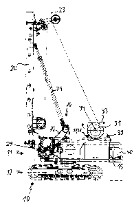
invention is shown in Figures 1 and 2. The construction device
has a carrier vehicle 10 with an undercarriage 12 and an upper
carriage 11, the upper carriage 11 being supported in a rotatable
manner on the undercarriage 12 about an approximately vertically
extending axis. On the front side of the upper carriage 11 a mast
element 20 is arranged, on which e.g. a drilling device can be
supported in a longitudinally
CA 02590488 2007-05-29
- 6 -
movable manner. A rope 23 extends in sections longitudinally
of the mast element 20, on which the drilling device can be
suspended for example. For winding up and unwinding the rope
23 a winch with a winch drum 31 is provided on the upper
carriage 11.
The mast element 20 is provided in a pivotable manner about
an approximately horizontally extending pivot axis 29 on the
carrier vehicle 10. In the condition illustrated in Fig. 1
the mast element 20 is located in an operating position, in
which it extends at least approximately in the vertical
direction. In the condition depicted in Fig. 2 the mast
element 20 is pivoted about the pivot axis 29 away from the
carrier vehicle 10 into an approximately horizontal transport
position, in which the mast element 20 protrudes forwards
from the front side of the upper carriage 11.
For the active pivoting of the mast element 20 an actuating
mechanism 70 is provided. The said mechanism has, amongst
others, a neck cylinder 71 that is hinged on the one hand to
the mast element 20 and on the other hand to a boom 72, which
is hinged for its part to the upper carriage 11.
The winch drum 31 is supported in a winch frame 33 by being
rotatable about an axis of rotation 34. The winch frame 33
has two bearing plates arranged on both front faces of the
winch drum 31. Through a roller bearing or a friction bearing
provided on the winch frame 33 the winch drum 31 is fixed in
a pivotable manner together with the winch frame 33 on the
upper carriage 11 about an approximately horizontally
extending pivot axis 39. This pivot axis 39 extends
approximately parallel to the axis of rotation 34 of the
winch drum 31 in the winch frame 33.
CA 02590488 2007-05-29
- 7 -
In the operating condition shown in Fig. 1 the winch drum 31
is located with the winch frame 33 in a first position above
the carrier vehicle 10. In the transport condition shown in
Fig. 2 the winch drum 31 is pivoted with the winch frame 33
about the pivot axis 39 behind the carrier vehicle 10 into
its rear part. To make this movement possible the pivot axis
39 is arranged in the transitional region between an
approximately vertically extending rear part 15 and the upper
side of the upper carriage 11 of the carrier vehicle 10. The
pivoting of the winch drum 31 from the first operating
position into the second transport position is accompanied by
a lowering of the axis of rotation 34 of the winch drum 31
and a reduction of the vertical clearance of the carrier
vehicle 10 determined by the winch drum 31 and the winch
frame 33.
In the operating condition depicted in Fig. 1 a counterweight
40 is arranged on the rear part 15 of the carrier vehicle 10.
This counterweight 40 has been removed in the transport
condition depicted in Fig. 2. In doing so a receiving portion
is cleared, into which the winch drum 31 is pivoted together
with the winch frame 33.
To fix the winch frame 33 with the winch drum 31 in the first
position at least one lug 17 is provided at the upper side of
the carrier vehicle 10. The lug 17 is arranged in such a
manner that it is aligned with a lug 37 provided on the winch
frame 33 when the winch frame 33 with the winch drum 31 are
located in the first position. To secure the winch frame 33 a
safety bolt can then be inserted through the two
corresponding lugs 17, 37.
Figures 3 to 5 show various embodiments of drives that can be
provided for pivoting the winch frame 33 jointly with the
winch drum 31.
CA 02590488 2007-05-29
- 8 -
According to the embodiment of Fig. 3 a rotary drive 51 is
provided in the area of the pivot axis 39 of the winch frame
33.
According to the embodiment of Fig. 4 a hydraulic cylinder 54
is provided, which is hinged on the one hand to the winch
frame 33 and on the other hand to the upper carriage 11.
According to the embodiment of Fig. 5 an actuating rod 57 is
provided, which is preferably of rigid design and is hinged
on the one hand to the winch frame 33 and connected on the
other hand to the actuating mechanism 70 provided for
pivoting the mast element 20. By such an arrangement it is
rendered possible that the driving means used for pivoting
the mast element 20 are also employed for pivoting the winch
frame 33 with the winch drum 31, in particular in a
simultaneous manner. In the present embodiment the actuating
rod 57 is provided on the boom 72 for the neck cylinder 71.
Basically, instead of the actuating rod 57 the neck cylinder
71 can also be connected to the winch frame 33 and used for
pivoting the winch drum 31.